manuals.online logo
Brands
  1. Home
  2. •
  3. Brands
  4. •
  5. Super Anchor Safety
  6. •
  7. Safety Equipment
  8. •
  9. Super Anchor Safety Quick-Strap User manual

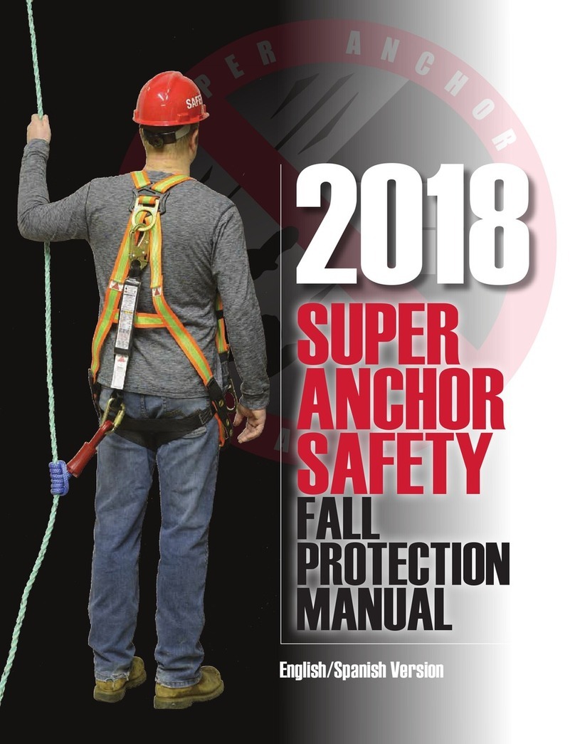
Super Anchor Safety Quick-Strap User manual

Manuel d’utilisation
Français canadien
Hinged AnchorTM
Includes Fasteners
Ancrage à charnières
avec fixations
Full Body Harness
Harnais de sécurité
Lifeline w/ Snaphook
Ligne de vie avec crochet
(Classe F, ajustable)
Instruction Manual
Canadian English
Shock Absorbing Lanyard
Ligne de vie avec absorbeur d’énergie E-4
Mechanical Rope Grab
Coulisseau de sécurité
Quick-StrapTM
Ancrage Quick-Strap
Version 2011©
SCN
Complies with CSA/ANSI/OSHA Standards
Conformes aux normes CSA/ANSI/OSHA
Super Anchor Safety (SAS) Phone | Téléphone: (425) 488-8868 www.superanchor.com
English |Français canadien Section English Page Page français
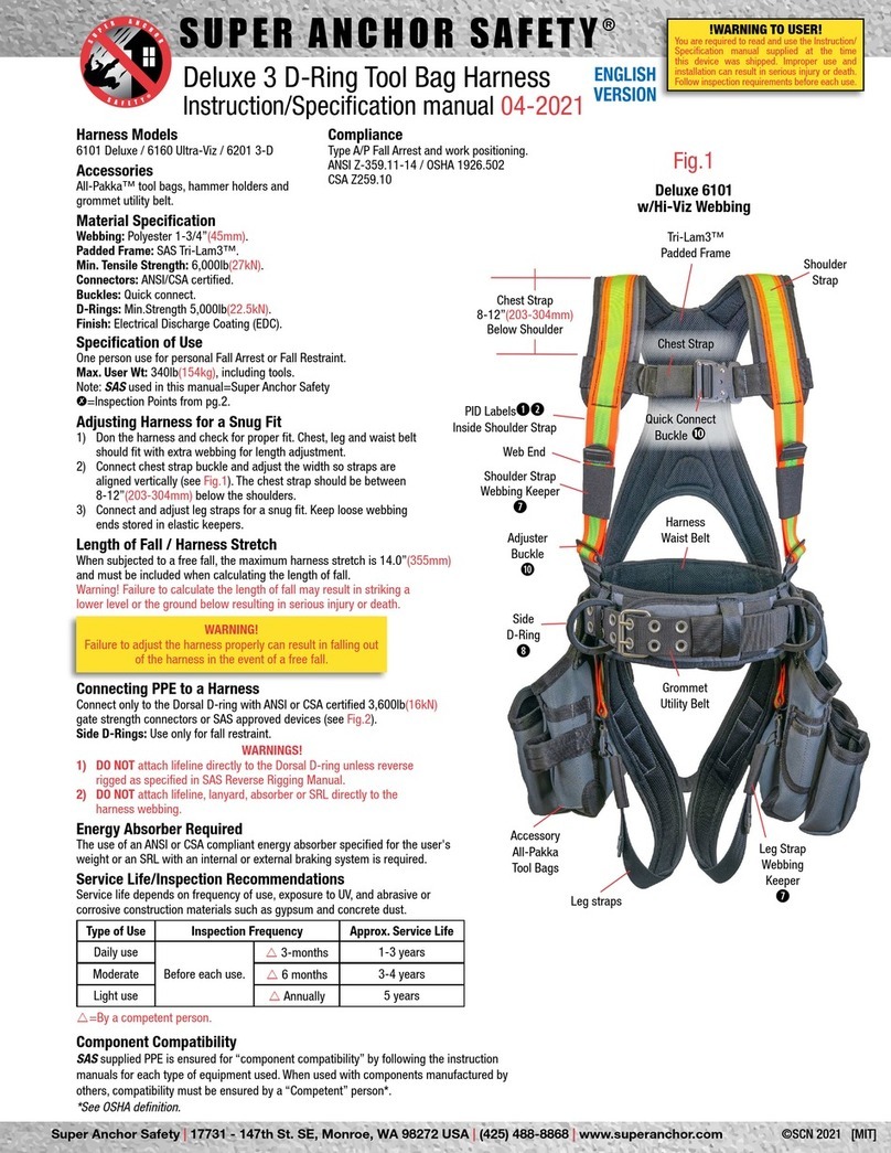
HARNESS ADJUSTMENT AND COMPONENT CONNECTIONS
AJUSTEMENT DU HARNAIS ET ACCESSOIRES DE FIXATION 12 12
INSPECTIONS: SHOCK ABSORBER / HARNESS
INSPECTIONS: ABSORBEUR D’ÉNERGIE/HARNAIS 23 13
ADJUSTING LIFELINE / ROPE GRAB TO LIMIT FREE FALL
AJUSTEMENT: LIGNE DE VIE/COULISSEAU DE SÉCURITÉ 34 14
ANCHOR SERVICE ZONES
SURFACE DESSERVIE PAR L’ANCRAGE 45 15
INSTALLING / MAINTAINING / INSPECTING ROPE GRAB
INSTALLATION/ENTRETIEN/INSPECTION : COULISSEAU DE SÉCURITÉ 5-A 6 16
INSPECTIONS: LIFELINE / SNAPHOOK
INSPECTIONS: LIGNE DE VIE/CROCHETS À RESSORTS 5-B 7 17
ANCHOR DEVICES: | DISPOSITIFS D’ANCRAGE
HINGED ANCHOR
ANCRAGE À CHARNIÈRES HINGED ANCHOR™ 6-A 8 18
QUICK-STRAP
COURROIE À ATTACHE RAPIDE QUICK-STRAP™ 6-B 9 19
COMPONENT COMPATIBILITY
COMPATIBILITÉ DES ACCESSOIRES 710 20
INSPECTION REPORT FORM
FORMULAIRE DE RAPPORT D’INSPECTION 11 21
USER TRAINING LOG
JOURNAL DE BORD 11 21
FALL HAZARDS
RISQUES DE CHUTES 822 22
FALL ARRESTER/VERTICAL LIFELINE
DISPOSITIF ANTICHUTE/LIGNE DE VIE VERTICALE 923 24
PRODUCT I.D./WARNING LABELS
ÉTIQUETTES D’AVERTISSEMENT/NUMÉRO DE SÉRIE 10 25 26
TABLE OF CONTENTS |TABLE DES MATIÈRES
CARACTÉRISTIQUES D’UTILISATION:
L’équipement de sécurité mentionné dans ce manuel est qualifié en tant que système
de protection contre les chutes et en tant que dispositif de positionnement pour un
ouvrier.Tel qu’il est mentionné à la section 7, l’équipement et les accessoires sont
compatibles. La compatibilité de l’équipement fabriqué par d’autres fournisseurs et
utilisé avec les produits SAS doit être garantie par un ingénieur*.
SPECIFICATIONS OF USE:
The equipment specified in this manual is rated for Fall Arrest and Fall Restraint/Work
Positioning for one person and is ensured for component compatibility as described
in section 7. Equipment mfg. by others and used with SAS equipment must have
compatibility ensured by“competent/qualified person”*.
HORIZONTAL LINES/MULTIPLE USERS:
The Quick Strap and Hinged Anchor are rated for two person use when there is no
exposure to a free fall. Not rated for Horizontal Lines.
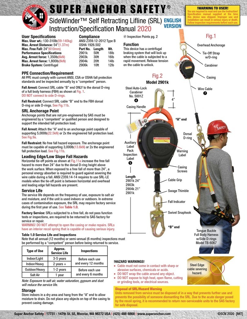
ENERGY ABSORBER/ROPE GRAB: Maximum user wt. is 220lb(100kg).
E-4 model I6061k or I6061 energy absorber is fitted with a Snap-hook for connecting
to the harness D-Ring. Maximum arrest force (MAF) for a 6’(1.8m)free fall is 900lb(4kN).
The deployment length is 42”(1.06m). Rope grab Nº4015M is factory attached to the
energy absorber and is rated at 3,600lb(16kN). Complies with CSA Z259.11-05 / ANSI
Z359.1 /OSHA 1926:502
FULL BODY HARNESS: Maximum user wt. is 220lb(100kg).
6,000lb(27kN) rated polyester webbing fitted with a proof loaded 5,000lb(22kN) rated
di-chromate plated D-Ring, Fall Impact warning labels and serial number/date of mfg.
label. Complies with CSA Z259.10-06 Class A.
LIFELINE:
5/8”(16mm)dia. 3-strand, 9,300lb(4,200kg)strength polyester lifeline fitted with a
plastic thimble and locking type Snap-hook.The rope splice is encapsulated with clear
shrink tube. Fitted with specification and serial number labels. Complies with CSA
Z259.11-05 class F adjustable lanyard. Complies with ANSI Z359.1 as vertical lifeline.
LIGNES HORIZONTALES/UTILISATEURS MULTIPLES:
D’une capacité d’ancrage de 2 ouvriers, la Quick-Strap™ et le Hinged Anchor™ peuvent
être utilisés lorsqu’il n’y a pas risque de chute libre. Usage non compatible avec les
lignes horizontales.
ABSORBEUR D’ÉNERGIE/COULISSEAU DE SÉCURITÉ: Conçu pour un poids
maximal de 220lb(100kg), l’absorbeur d’énergie E-4 (modèle I6061k ou I6061) est
muni d’un crochet à ressort pour l’attacher à l’anneau en D du harnais. La force d’arrêt
maximale (FAM) lors d’une chute libre de 6pi(1.8m) est de 900lb(4kN). L’allongement
maximal est de 42”(1.06m). Le coulisseau de sécurité Nº4015M est fixé en usine à
l’absorbeur d’énergie. Il a une capacité de 3 600lb(16kN). Conformes à la norme CSA
Z259.11-05 / ANSI Z359.1 /OSHA 1926:502
HARNAIS DE SÉCURITÉ: Conçu pour un poids maximal de 220lb(100kg).
Fait de polyester d’une capacité de 6 000lb(2 721kg), le harnais est muni d’un anneau
en D bichromaté d’une capacité de 5 000lb(2 267kg), d’étiquettes d’avertissement
contre les chutes et d’une étiquette du fabricant (numéro de série/date de fabrication).
LIGNE DE VIE:
D’un diamètre de 5/8”(16mm), cette ligne de vie en polyester trois fils a une capacité
de 9 300lb(4 200kg) et est munie d’une cosse en plastique et d’un crochet à ressorts
verrouillable. L’épissure est encapsulée dans une gaine de protection transparente. La
gaine est munie d’une étiquette d’avertissement et du numéro de série. La ligne de vie
ajustable classe F est conforme à la norme CSA Z259.11-05.
*Qualified Person: According to the definition of the Industrial Safety Standards for your area. *Ingénieur: selon la définition des normes de sécurité industrielle régissant votre type de travail
Property of | Propriété de: Purchase Date | Date d’achat:
Super Anchor Safety (SAS) Phone: (425) 488-8868 www.superanchor.com
SECTION 1 HARNESS ADJUSTMENT AND COMPONENT CONNECTIONS
Fig.3
Fig.4
Fig.1
Shoulder Strap
Chest Strap
Position
(armpit height)
AdjustWebbing
Through Slots in
D-Ring Pad
Fall Impact Label
Inspect before each use.
D-Ring Pad
D-Ring
Fall Impact Label
Shock/Energy
Absorber
Rope Grab
Make Sure“Arrow”on
Rope Grab is Pointed
Toward Anchorage
Point
Shoulder Strap
Arrow
Fig.7Fig.6
At an Angle
Leg Strap
Friction Buckles
ADJUSTING A NEW HARNESS:
Hold the harness by the metal D-Ring. Unbuckle the
chest strap and leg strap friction buckles. Remove
any twists in the webbing. Insert arms through the
shoulder straps so the D-Ring is on your back and the
arrow indicator on the shoulder strap, shown at Fig.3,
is pointing up toward your head. Leg straps should be
hanging down with no twists or tangles. Adjusting for
personal fit may require the harness to be put on and
taken off a few times.
CHEST AND SHOULDER STRAP
ADJUSTMENT:
1. Align the shoulder straps so they are parallel to
each other as shown at Fig.1. Buckle the chest strap
by inserting buckle “A” through buckle “B” as shown
at Figs.5, 6 and 7below. Adjust the chest strap
length by moving the webbing through buckle “A” so
the shoulder straps do not extend past your armpits.
For an average size person the length between the
shoulder straps should be no more than 12”.The chest
strap should be positioned at armpit level as shown
at Fig.1.
Note: Shoulder StrapWebbing is Adjusted by
Shortening or Lengthening the Leg Straps
DRING ADJUSTMENT:
3.The D-Ring on harness back should position about the center of the shoulder
blades as shown at Fig.2. Position the D-Ring pad at least 4”below the top of your
shoulders but no more than 6”. Adjust the D-Ring location by moving the webbing
through the slots in the D-Ring pad (Fig.3) and taking up excess webbing through
the leg strap friction buckles (Fig.1).The chest strap position may have to be
adjusted after moving the D-Ring pad.
4. Connect shock absorber as shown at Fig.3 to the back of the D-Ring on the
harness with the Snap-hook. Make sure the Snap-hook functions properly by
following instruction in Section 5-B.
5. Lifeline should be installed through the rope grab with the arrow indicator
pointing toward the anchor-point end of the lifeline shown at Fig.4. Follow the
instructions for the rope grab adjustment at Section 3 before use.
FRICTION BUCKLES:
7. Friction buckles are locked by inserting the smaller “A” buckle through the larger
“B” buckle (Fig.5).Turn “A” buckle at an angle as shown at Fig.6 and slide through
“B” buckleThe “A” buckle should lay flat over the top of the “B” buckle as shown at
Fig7.
Fig.5
Insert Small Buckle “A”
Into Large Buckle “B”
“A” “B”
6. Attach lifeline to anchorage device with
the Snap-hook. Ensure the Snap-hook is
locked and the lifeline is not twisted or
entangled.
LEG STRAP ADJUSTMENT:
2. Buckle the leg straps and adjust for a
snug fit. Shorten or lengthen the strap
by unbuckling and moving the webbing
through the “A” buckle.
WEBBING KEEPERS:
8. Excess webbing from the chest and leg/shoulder straps are stored using the
plastic webbing keepers shown at Fig.7.Webbing strap ends are terminated by
folding over and sewing in place.This prevents the webbing from sliding back
through the “A” buckle. For this reason, do not cut off excess webbing.
If termination overlaps is missing do not use the harness.
WARNING:
IF THE HARNESS IS NOT
ADJUSTED FOR A SNUG FIT,
IT IS POSSIBLE TO COME OUT
OF THE HARNESS IF YOU FALL.
THE CHEST STRAP MUST BE
CLOSED AND BUCKLED AT
ALL TIMES WHEN YOU ARE
WEARING THE HARNESS
FOR FALL PROTECTION.
Buckle “A” Lays Over
theTop of Buckle “B”
Webbing
Keepers
“A”on Top
2
Fig.2
Max Length
Below Shoulder
Harness
D-Ring at
Center of
Back
Approx. 12”
Super Anchor Safety (SAS) Phone: (425) 488-8868 www.superanchor.com
Fig.4Fig.3
D-Ring Pad
(front side)
Direction
Arrow Label
D-Ring
Intact
Fall Indicator
Good to Go!
3
SECTION 2 INSPECTIONS: SHOCK ABSORBER / HARNESS
Fig.8
Fig.9
Fig.5
Fig.7Fig.6
Webbing
Keepers
Chest
Strap
D-Ring Pad
(back side)
Shoulder
Straps
Chest Strap
Webbing
Holders
Warning Labels
See section 10
WebTermination
Sewn and Not Loose
or Missing
Slots not
broken or
missing
Slots not
broken or
missing
Fall Indicator
Deployed
DO NOT USE!
This Part will be
Visible if Harness
Subjected to Fall Stitch Pattern on Front and Back
Have no Cut or Broken Stitches Underside ofWebbing Overlap
Have no Cut or Broken Stitches
Buckle
“A” Fits
Through
Buckle
“B” and
Lays Flat
Fig.2 Fig.1
Snap-hook
Attached
Rope-Grab
N°4015M Attached
Web Loop
NotWorn
or Cut
Web Loop
NotWorn
or Cut
Front Side
Plastic
Shrink
andTube
Warning
Label
Plastic
Shrink
Tube is
Missing
Length is
Approx.
17”
(430mm)
Maximum
42”
(1.06m)
Shock Absorber
Has Been Deployed
(ripped out)
Back
Side
“A” “B”
ABSORBER FABRIC:
The absorber cover fabric is black polyester.
The tear away webbing is white polyester.
The shock absorber is designed to arrest a fall one time only and it must be replaced. The
original length is approximately 17”(430mm).When the absorber is subjected to a free fall the
tear-away fabric will rip out a maximum of 42”(1.06m)as it slows the fall and then comes to a
complete stop. It takes about 650-750 lbs of force to deploy or initiate the rip out function.
1. ENERGY ABSORBER E4:
Factory attached E-4 Energy absorber N°I6061k or I6061 has a maximum user wt. of
220lb(100kg)shown at Fig.1. Do Not Remove from Rope-Grab.
REMOVE FROM SERVICE IF ANY OF THE FOLLOWING INSPECTIONS FAIL:
a) Snap-hook or rope grab are missing.
b) Snap-hook does not pass inspection in Section 5-B.
c) Web loop at Snap-hook or rope grab are worn or cut.
d) Clear shrink tube cover is missing, cut, or damaged. Fig.2-B.
e) Warning label is missing.
f) The absorber has been fully or partially deployed in a fall or by applying some other
force as shown at Fig.2-A. and is longer than the factory length of 17”(430mm).
g) Webbing stitching is missing, cut, or loose.
2. BODY HARNESS:
REMOVE FROM SERVICE IF ANY OF THE FOLLOWING INSPECTIONS FAIL:
a) Webbing is cut or damaged in any way.
b) Webbing stitches are loose, pulled apart, broken or cut. Fig.6. Inspect webbing over-
laps and stitches on the underside of stitch pattern as shown at Fig.7.
c) Friction buckles are bent, cut, damaged or corroded. Small buckle “A” inserts through
buckle “B” and locks in place. Fig.8.
d) Chest strap webbing holders (black plastic) are broken or missing. Fig.5.
e) D-Ring chafe pad slots where webbing passes through are broken. Inspect back side of
pad. Fig.4.
f) Front side of chafe pad D-Ring is missing, broken, cracked or corroded. Fig.3.
g) Plastic webbing keepers and webbing terminations are loose, broken or missing. Fig.8.
h) Fall indicator or warning labels are missing. Fig.3, 9.
Fall Indicators Shown at Fig.3:
Fall Indicators sewn into the webbing are located below the D-Ring. Inspect before each
use.When subjected to a free fall or other force, the Remove From Service warning will
be visible. Remove harness from service immediately!
Tear
Away
Fabric
Super Anchor Safety (SAS) Phone: (425) 488-8868 www.superanchor.com
SECTION 3 ADJUSTING LIFELINE / ROPE GRAB TO LIMIT FREE FALL
4
OSHA 1926:502(d)(16)(iii) Allows a worker to free fall no more than 6’(1.8m)before
his equipment begins to arrest the fall. During a fall the rope grab device locks
onto the lifeline when all the slack of the various components are taken up in the
fall.The shock absorber will deploy, slow the fall, and the worker will come to a
complete stop before contacting the ground or lower level.
ADJUSTMENT SLACK EXAMPLE:
The length from the harness D-Ring
to the leading edge is 52”(1.3m)(B).To find
the amount of adjustment slack,
deduct 52”(1.3m)from 72”(1.8m).
The“adjustment slack”in the lifeline
is 20”(.5m)(C)
The 6’(1.8m)length is measured from the“leading edge”(as shown at Fig.1, where
the worker is standing) to the point where the equipment begins to arrest the fall.
(Fig.1 foot position to Fig.2 foot position).
The following method to gauge a free fall is a
recommendation only and all measurements in this manual
are EXAMPLES ONLY. Each worker will need his own personal
fall protection plan.
MEASURE THE D-RING LENGTH:
From a standing position, measure the length from your
harness D-Ring to your feet. Deduct this length from
72”(1.8m).This is the amount of“adjustment slack”for your
own personal fall protection plan.
Fig.1
Fig.2
Fig.3
Harness D-Ring
Rope Grab
Tension
Position
Move Rope Grab
20”(.5m)Down Line for
Adjustment Slack
Limiter Knot
Position
(Optional)
Lifeline
inTension
Leading
Edge
(B)
D-Ring
Height
52”(1.3m)
(A)
72”(1.8m)
Free Fall
Length
(C)
Adjustment
Slack
20”(.5m)
(D)
Absorber
Deployment
42”(1.06m)
Full Arrest
Position
Foot Position
(E)
12”(305mm)
Harness
Stretch
Approx. Free Fall Length
(F)
11’6”(3.5m)
ADJUSTING ROPE BRAB FOR FREE FALL LENGTH:
1. Position your rope grab a few feet below the Snap-hook on your lifeline with
the rope grab arrow pointing toward the anchor-point end of the lifeline as shown
at Section 1, Figs.3 &4, and connect your lifeline to a properly installed anchor
point.
2. Position the shock absorber/rope grab under your arm as shown at Fig.1 above,
and descend in a straight line toward the leading edge while holding the rope grab
locking lever in the open position shown at Section 5-A, Fig.2. Slide the rope
grab down the lifeline keeping all the slack out of the line.
3. With your feet at the“leading edge”* position, release the rope grab locking
lever. The shock absorber and rope grab should be in tension as shown at Fig.1.
Mark the position of the rope grab on the lifeline. At this position your free fall
should be no more than the length of the D-Ring to the leading edge: 52”(1.3m)as
shown at Fig.1, (B) of our example.
4. Slide rope grab down the lifeline 20”(.5m), as shown (C) in our example. The
adjustment slack added to the lifeline length will allow you to move in a radius to
the left or right of the anchor center point while limiting your free fall to 6’(1.8m).
As you continue to advance along the leading edge, the adjustment slack will reach
its maximum length at the“anchor service-zone”overlap, which is the intersection
along the leading edge shown at Section 4, Fig.3.The lifeline will be in tension.
In order to continue working along the leading edge, the worker will have to
connect to a different anchor point.
LENGTH OF FALL:
The approximate length of a fall shown at Fig.3 included the following: Free-fall 72”(1.8m)(A), absorber
deployment 42”(1.06m)(D) and harness stretch 12”(305mm)(E). Note: rope grab deceleration is less
than 12”(305mm). Approximate length of fall from leading edge to full arrest is 11’6”(3.5m). (F)
NOTE: The“length of fall”may vary depending on the harness D-Ring height of the individual worker and
how well the harness is adjusted for snug fit. Calculate your own personal fall protection plan to avoid con-
tacting a lower level or the ground if you fall.
Ground, lower level, or hazard below
20”
(.5m)
20’(6m)rafter length
Class F Ajustable Lanyard /Vertical Lifeline
Super Anchor Safety (SAS) Phone: (425) 488-8868 www.superanchor.com
Fig.4
Fig.3
Fig.2
Anchor
Point
“A”
Anchor
Point
“B”
Lifeline
Position
“B” Lifeline
“A”
Maximum Limit
of Travel at Zone
“A”Leading Edge
Service Zone “B” Radius Service Zone “A” Radius
Limiter
Knot
Rope
Grab
Leading Edge
Service Zone
Overlap Area
Fig.1
Ridge
Radius
Slope Anchor Point
“A”
Service Zone
“A”
Leading Edge
Free Fall Hazard
These Areas Not
Protected by
Zone“A”
5
SECTION 4 ANCHOR SERVICE ZONES
SERVICE ZONE:
An“anchor service zone”is the area of fall protection provided by a single anchor point.
A lifeline attached to an anchor point becomes a radius line that creates a 360° circle
over the work area as shown at Fig.1. When a portion of the circle extends beyond the
leading edge as shown by the blue shaded area at the bottom of Fig.1, the worker is
exposed to a free fall. In order the limit the free fall to no more than 6’(1.8m), the worker
needs to adjust his position on the lifeline by using the rope grab shown at Section 3,
Fig.1.
ANCHOR LOCATION:
Some anchors can be installed as permanent fixtures, while others serve as temporary
anchor points that are removed after use.“Anchor service zones”provide a way to
calculate how many anchors may be needed and where to locate them.
USING SERVICE ZONES TO LIMIT FREE FALL:
A single anchor point shown at Fig.1, provides fall protection for the entire area within
the radius of anchor“A”, while limiting free fall to 6’(1.8m)along the leading edge fall
hazard. The area outside the“A”“service zone”will require using another anchorage point.
EXAMPLE: Lifeline“A”rope grab position is adjusted 20”(.5m)from the leading edge so
as to limit the free fall to 6’(1.8m)as shown at Fig.4.The worker may travel to any area
on the work surface that is inside service zone“A”as long as there are no other exposures
to a fall hazard. When working along the leading edge where zone“A”overlaps into zone
“B”shown at Fig.3, the worker can not travel into zone“B”Leading Edge because the
rope grab position on the lifeline has reached its limit. In order to do work in zone“B”
along the leading edge, the worker will have to disconnect from anchor point“A”and
connect to anchor point“B”as shown at Fig.2, resulting in limited hazard exposure.
Note: Limited hazard exposure may be reduced by using a two lifeline/rope grab system.
While still connected to rope grab“A”, attach Iifeline rope grab“B”then disconnect rope
grab“A”. If the worker unlocks the rope grab and continues to move
along the leading edge, the free fall will be greater than 6’(1.8m).
As the worker at Fig.4 travels along the leading edge toward Fig.3,
the rope grabs fixed position on the lifeline will force him up-slope
sway from the leading edge where zone overlaps occur.
WARNING: FALL HAZARD—
Note: If the rope grab is adjusted on
lifeline“A”to allow travel into zone“B”,
the free fall and swing fall hazard will
become greater than 6’(1.8m) Refer to
Section 8 for common fall hazards
SAFETY STATISTIC:
Falls from elevated work
surfaces are among the top
3 leading causes of death on
construction sites in the US.
NOTE: A Jobsite safety Plan (JSP) or
personal fall protection plan may allow for
limited duration exposure to free falls.
LIMITER KNOT:
The rope grab position on the lifeline is used as a reference point for the
free-fall based on the adjustment slack. However during the course of work
the rope grab position can change.To mark or gauge the adjustment slack
position at Section 3, Fig.1, a limiter-knot may be tied just below the rope
grab as a gauge to mark the maximum free fall length.
Super Anchor Safety (SAS) Phone: (425) 488-8868 www.superanchor.com
SECTION 5-A INSTALLING / MAINTAINING / INSPECTING ROPE GRAB
6
Mechanical Rope Grab Nº4015M is required to be used with an energy absorbing device when free fall hazards exist. For CSA this device is certified for use on 5/8”(16mm)
lifelines supplied by Super Anchor Safety (SAS) only. Not certified for use on lifelines manufactured by others. WARNING: If the Rope-Grab is not installed with arrow
pointing up serious injury or death may result In the event of a fall.
BEFORE USE: TEST LOCKING FUNCTION:
Before each use verify arrow indicator is pointing up to the lifeline connector end. Perform locking function test shown at Figs.2 and 3.
Do not use if locking function test fails. Do not use if the lifeline fails section 5-B inspections.
Fig.1
Rope
Chamber
Locking
Cam
Lever
Shock
Absorber
Attachment
Ring Cam Foot
Cam Foot
Anchor Attachment
End of Lifeline
Locking Cam
Return Spring
Inside
Direction
Arrow Points
to Anchor
Attachment
End of Lifeline
Termination
Knot 2”(50mm)
From Tail End
Termination
Knot
4”(100mm)
From Tail End
2”(50mm)
ShrinkTube
atTail End
of Lifeline
ShrinkTube
atTail End
of Lifeline
Check Each
Side For a
Total of 4
Rivet Heads
Fig.2 Fig.3
Push Cam Lever
Forward to Unlock
Locking Cam Open Position
Lifeline Slides easilyThrough Rope Grab Should Not
Move on the Lifeline
Locking Cam
Closed Position
INSTALLATION/REMOVAL OF THE ROPE GRAB:
Canadian Max Kits: Class F-Lanyards are required to have a termination that prevents the Class II
Integral Adjuster (rope-grab) from being removed off the lifeline. Fig.1a.
USA Max Kits: Are fitted with a termination knot (Fig.1b), that may be untied to allow the rope-
grab to be removed by following instructions shown at Fig.2. Warning:The termination knot
IS REQUIRED to prevent accidental disengagement of the Rope-Grab in the event of a
fall or during normal use.
INSTALLING THE ROPE GRAB/ USA USE ONLY:
With the direction arrow pointed toward the anchor attachment, hold the rope grab in the openy
position shown at Fig.2 and insert the tail end of the lifeline through rope grab chamber.
Re-tie the termination knot 4”y(100mm)from the tail end of the lifeline.
CLEANING/MAINTAINING/INSPECTING THE ROPE GRAB:
Normal use of the lifeline will cause the rope diameter to enlarge as the lifeline absorbs dirt and dust.
Although this will not prevent the rope grab from locking onto the lifeline, it may become difficult
to move the rope grab up and down the lifeline. Check for abrading of the lifeline, cut or damaged
filaments, paint, caulking, or other contaminants on the lifeline which can also interfere with the rope
grab movement. Debris can also get trapped inside the rope grab device and may require cleaning.
CLEANING THE ROPE GRAB:
Note: For CSA the Rope-Grab may not be removed from the lifeline. Use air pressure to clean. Do
not use lubricants and do not allow solvents to come in contact with the lifeline. For USA the rope
grab may be removed for cleaning.
INSPECTING THE ROPE GRAB:
a) Check for debris in the locking cam
b)Make sure all locking lever rivets are intact and none are missing or broken
c) Move the locking lever to the open position shown at Fig.3. Release the locking lever and
it should return to the closed position shown at Fig.3. A failure to close may be caused by a
broken or damaged locking cam return spring or some other damage. Check for broken spring
or trapped debris inside the rope grab.
d)Make sure the Rope Grab attachment ring, locking lever, or any other components are not
broken, cracked or distorted in any way.
WARNING: IF THE RETURN TO LOCK FUNCTION DOES NOT WORK, THE ROPE GRAB WILL
FAIL WHEN SUBJECTED TO A FREE FALL IMPACT. IMMEDIATELY REMOVE FROM SERVICE.
Do not use if damaged. If the rope grab is subjected to a free fall, it must be removed from
service and not used again.
2”
(50mm)
Nº4015M
Rope-Grab
CSA Class II
Integral
Adjuster
Fig.1a
Required for CSA
Class F-Lanyards
Fig.1b
For use in
USA only.
Super Anchor Safety (SAS) Phone: (425) 488-8868 www.superanchor.com
7
SECTION 5-B INSPECTIONS: LIFELINE / SNAP-HOOK
USER INSPECTIONS:
All components of a personal fall protection system need to be inspected before each
use by the person using the equipment. The inspection procedures in this manual are
recommendations only and should be used as a guideline for your own inspection plan.
EMPLOYERS/USERS CERTIFICATION INSPECTION:
A scheduled or routine inspection of all safety equipment should be carried out by a
“qualified”or“competent”*person to ensure that all components are free from defects.
Such an inspection should consider the specific type of work being done, job site
conditions to which the equipment is exposed, and the frequency of use.
1. SPLICE AND EYE THIMBLE:
Remove from service if any of the following conditions are present:
a) Plastic eye thimble is oval, oblong, cut, smashed, or melted. Fig.2-D.
b)Thimble is missing from the lifeline. Fig.2-C.
c) Shrink tube plastic cover and warning label are missing. Fig.2-C, D.
d) Rope strands are pulled loose, sticking out, or splice is coming loose. Fig.2-C, D.
2. LIFELINE:
Inspect the entire length of the lifeline for defects and remove from service if the
following conditions are present:
a) Rope strands are cut or sticking out as shown at Fig.2-A and 2-B.
b) Signs of chemical or heat damage; such as melted or distored strands.
c)Tail end of rope is coming undone, frayed because the shrink tube termination is
missing, or the rope has been cut.
d) Termination knot is missing. Fix by re-tying.
3. SNAP-HOOK FUNCTION TEST:
Theauto-lockSnap-hookhastwo internalspringsthatcausethegatetoremaininthelocked
position. To pass inspection, the gate must remain locked when the safety is released.
SAFETY LOCK TEST:
a) Push down on the safety lock as shown at Fig.3 and release. The safety should
spring back to the closed position.
LOCKING GATE TEST:
b) As shown at Fig.4 push on locking gate only and do not push on the safety lock.
The gate should not move at all.
c) Hold the Snap-hook in hand as shown at Fig.5 and push down on the safety
lock. The locking gate should open. Release the safety lock the gate should close
by itself. Make sure all moving parts do not have any contaminants inside or outside
that might interfere with the opening and closing of the gate, such as caulk or
roof cement.
SNAP-HOOK FRAME:
The Snap-hook frame shown at Fig.6 does not have any defects. If the frame locking
gate, or safety lock mechanism is bent, distorted, cut, gouged, or damaged in any way,
remove it from service.
To“REMOVE FROM SERVICE”
means DISPOSE OF and DO NOT USE.
Fig.3 Fig.4 Fig.5 Fig.6
To Open Lock
Push Down
Safety Lock Closed
Gate Should Not Open Safety Lock Open
Allows Gate to Open Snap-hook
Frame is Straight
Safety Lock
in Closed
Position
Gate
Won’t
Open
To Open
Gate
Push In
Hook
Safety Lock Closed
Position
Rivets
Locking
Gate
Fig.2
“A”
“C”
“B”
“D”
FAIL INSPECTION; REMOVE FROM SERVICE.
Strand
CutThrough
Eye Thimble
Missing
Splice
Coming
Loose
Cover
Missing.
Warning
Label
Missing.
Strand Cut
or Damaged
Oblong or
Oval Shape
Thimble
Cut Clear Plastic
Splice Cover
Tail End
Shrink Tube
Cover
Splice
Length
Approx.
6”(150mm)
Snap-hook
Attached
Minimum
4”
(100mm)
Fig.1
NOTE: Fig 1 Shows a Lifeline
System.With NO Defects
Eye Thimble
Is Round
3-Strand
Eye Splice
Warning
Label
Grab Locks
Onto Lifeline
ROPE GRAB:
Arrow on Grab
Must Point
Toward Splice
Termination
Knot Shown
USA only.
See Pg. 6
Fig.1a for
CSA.
Super Anchor Safety (SAS) Phone: (425) 488-8868 www.superanchor.com
SECTION 6-A INSTALLING HINGED ANCHOR™
Leg
Side Nail
Holes
Fastener
Holes
Leg “A”
ADJUSTABLE HINGED ANCHOR™
Re-usable 11ga. di-chromate plated legs fitted with a proof loaded D-Ring. Install at the peak or in the field
that is sloped less than 20/12 (60°). Installs over 7/16”(11mm)or greater thickness OSB/Plywood sheathing
attached to a minimum 2x4 top chord or truss as shown at Fig.1 and Fig.5. Leg“A”is stamped with basic
instructions. Remove from use anchors that are damaged or have been subjected to a fall impact.
DO NOT USE IF ONE LEG MISSING. Framing must be capable of supporting 5,000lb(22kN) or two times the
intended load if safety standards allow.
FACTORY CERTIFIED FASTENERS:
Use only SAS Factory supplied fasteners and replacement fasteners DO NOT SUBSTITUTEWITH GENERIC
FASTENERS. Use fasteners only once and dispose of after use.
WARNING:
DO NOT REUSE NAILS OR
SCREWS AFTER REMOVAL
Because the Strength of the
Fasteners will be Reduced.
DO NOT USE GALVANIZED 16d
INSTEAD OF VINYL SINKERS
REMOVING ANCHOR:
Pull nail heads only. Remove the screws by unscrewing. Do not
remove the anchor by prying the underside of the anchor leg or by
pulling on the D-Ring. Prying or pulling on the D-Ring or anchor legs
can result in damage to the D-Ring itself or the welds that attach the
D-Ring to the legs.
ANCHOR FASTENING REQUIREMENTS:
The total number of fasteners (T) requires an equal amount to be
installed through each anchor leg. 24T= 12 fasteners for leg A and
12 fasteners for leg B.
INSPECTION:
a) Examine the anchor legs for deformation, cracks or other
signs of damage.
b) Inspect the D-Ring and attachment tabs at the legs for
cracking, deformation, broken welds or other signs of damage.
c) The D-Ring must rotate freely without binding or
forcing them open.
FRAMING INSPECTION REQUIRED:
Inspection underside of framing/sheathing at the anchor
location and make sure none of the center top chord fasteners
are visible through the sides of the top chord. Inspection
failure requires to re-install at another location.
Note: Specification for anchor attachment through sheating only
is not in this instruction. Consult Universal Anchor Manual.
VCS:VINYL COATED SINKER. DPLX: UNCOATED DUPLEX. HHS: HEX HEAD SCREW
NOTE:/T=TOTAL NUMBER OF FASTENERS REQUIRED FORTOP CHORD AND SHEATHING
FASTENER MATRIX: Number of Fasteners Required
Fasten Into Center
OfTop Chord FastenThrough
Sheathing
Fastener See
Part # No. Type 3,000lb
(13.5kN)
5,000lb
(22kN)
3,000lb
(13.5kN)
5,000lb
(22kN)Fig. #
3007 24 16dVCS 12/12T 12/24T 12/24T 2
3012 12 16d DPLX 12/12T 12/24T 12/24T 4
3008 12 HHS 12/12T 3
#12x1-5/8”
2011 30 #12x1-5/8” 24/24T 30/30T 2
2009 10 #12x2-7/8 10/10T 3
8
Fig.1
Fig.4Fig.3Fig.2
Fig.5
6- 16d
Nails 1 Nail ea.
Corner 6
#12x1-5/8”
(42mm)
Screws
Center
Row
Leg
“A”
6-16d
Duplex
Nails
Center
Row
Leg
“A”
1 Nail ea.
Corner
1 Nail ea.
Corner
24
VCS/DPLX
5,000lb(22kN)
Rating
12
VCS/DPLX Nails
3,000lb(13.5kN)
Rating
12-1-5/8”(42mm)
10-2-7/8”(72mm)
Screws
5,000lb(22kN)
Rating
1 Nail ea.
Center
Side
6
Screws
Center
Row
Leg
“B”
6
Nails
Center
Row
Leg
“B”
1 Nail ea.
Center
Side
Center
Row
Leg
“A”
Center Row
Fasteners:
Center on
Top Chord
Minimum 2x4
Top Chord Minimum
7/16”(11mm)Sheathing
Min. 2x4
Top Chord
Edge Nails
Penetrate
Sheathing
Only
6
Nails
Center
Row
Leg
“B”
D-Ring
D-Ring
Tabs
Anchor
Leg
Minimum
4”
(100mm)
Super Anchor Safety (SAS) Phone: (425) 488-8868 www.superanchor.com
9
SECTION 6-B QUICK-STRAP™
ATTACHMENT SPECIFICATIONS:
The Quick-StrapTM is designed to be wrapped around a rafter, truss top chord,
header, beam, or other structural member that is capable of supporting
5,000lb(22kN)or two times the intended fall protection load when Industrial
Safety Standards permit.
INSTALLATION METHOD:
Wrap the Quick-Strap around the supporting structure and insert the
D-Ring through web loop end shown at Fig.2 and 3. Cinch tight with the
webbing flat against the tie-off surface. Do not allow twists or knots to
form. Blocking or sheathing is required on sloped or flat chords as shown at
Fig.4 to prevent movement on the top chord. For installation or removal
when sheathing is present, cut a 4”x4”(100x 100mm) evacuation hole over
the top chord center as shown at Fig. 5. Attach to the D-Ring with a locking
Snap-hook or locking Carabiner. DO NOT tie a lifeline or lanyard directly to
the D-Ring or connect a Snap-hook to the web loop end (see Section 7).
The web loop end may be inserted through the D-Ring only when using a
locking type Carabiner as a connector.
WEBBING HAZARDS:
Avoid contact with sharp edges, exposed fasteners, hanger hardware, truss
web connector plates, high heat, petroleum products, chemicals, caulk, wet
concrete, wet stain, wet paint, solvents, Rice Krispies or liquids that could
degrade or weaken the webbing.
MAINTAINANCE:
Do not store if webbing is wet or damp. Mildew can form and deteriorate
the webbing and stitching. Do not dry using high heat. To remove
moisture: hang in an open area at room temperature or outside in warm
air. Clean webbing using compressed air or wash with warm water and
mild detergent. DO NOT USE SOLVENTS OR CHEMICAL CLEANING AGENTS ON
WEBBING.
INSPECTION:
Before each use inspect D-Ring for cracks, cuts, gouges, deformation or
elongation. The D-Ring should lay flat and be perfectly round. Inspect the
stitching for cut, broken, or damaged stitches. The webbing must be free
of cuts, abrasions, punctures, or contaminants. Examine the inside of the
webbing loops where they attach to the D-Ring and web loop end. Remove
from service if inspection fails or the strap has been subjected to a free fall.
NON-SPECIFIED USES:
Do not use as a permanent tie-off point. Do not use for lifting, hoisting,
towing, or securing of loads. Do not link two or more straps together.
SERVICE LIFE:
Webbing products in regular outside use should be removed from service
and replaced annually. Do not leave exposed to moisture or high UV
exposure for prolonged periods.
QUICK-STRAP SPECIFICATION: PART #3005
Fabricated with two layers of 1-3/4”x 48”(45mm x 1.2m) red polyester webbing sewn
together. Fitted with a proof loaded di-chromate plated D-Ring on the connector attach-
ment end and a web loop on the opposite end. Rated for single person use with a maxi-
mum body weight of 310lb. May be used for 2 persons for fall restraint or work positioning
only. Energy/Shock absorbers must be worn.
Fig.2 Fig.1
Fig.3
Fig. 4
Fig. 5
Insert D-Ring
Though
Web Loop End
Correct Position of
D-Ring Through
Web Loop
2”x 4”Top Chord
Wrap Around
theTop Chord
and Prevent
Movement with
Sheathing or
Blocking
4”x 4”(100x 100mm)
Evacuation Hole in
the Sheathing for
Easy Removal
Inspect Box
Stitching for
Cuts/Breaks
Web Loop
D-Ring
End
D-Ring
Web Loop
w/Wear Pad
Webbing
Body
Warning
Label
48”(1.2m) Length
SAS Model #3005
Super Anchor Safety (SAS) Phone: (425) 488-8868 www.superanchor.com
Fig.4
Fig.5
Harness
D-Ring
Absorber
w/Snap-hook
and Web Loop
Mechanical
Rope Grab
#4015M Value
Rope Grab™
#4015V
Super
Grab™
#4015
Web Loop
SECTION 7 COMPONENT COMPATIBILITY
10
Fall Protection components are linked together with web loop ends shown at Fig.5, rope thimbles shown at Fig.3
and D-Rings shown at Fig. 4. The two primary connectors used to link components are double locking type Snap-
hooks shown at Fig.1 and carabiners shown at Fig.2. During a free fall all components and connectors are linked
properly and are ensured for component compatibility to prevent accidental or unintentional disengagement. That
means using equipment for the purpose it was designed and following industrial safety standards and manufacturers
specification for use.
NON-COMPATIBILITY
Warning: Linking components that are not designed to be used together can result in serious injury or death. Never
attach two connectors together and do not connect a Snap-hook to a web loop as shown at Fig.6.
EXEMPT FROM COMPLIANCE STANDARDS:
ANSI and CSA currently do not have safety standards that apply to the Super Grab™,Value Grab™, or anchorage
devices. SAS tests and certifies our equipment to meet the intent of OSHA 1926:502. Compliance letters
from US Dept of Labor, WISHA, and Cal-OSHA
are available upon request. MAX Lifeline
w/Snap-hook
X-Line™
Air Hose
Rope
Thimble
5-K™, Formit™
ARS™ -Series
Wall-Mount™
Tie-off Straps
Truss Bar™
Universal
Anchor™
Hinged
Anchor
Safety Bar™
RS-20™ and
RS-10™
RetroFit™ and
TileRetro™
Snap-Hook
ALL OF THESE
CONNECTIONS ARE
COMPONENT
COMPATIBLE
Note: Not all anchorage devices Mfg. By
Super Anchor Safety are shown.
Carabiner
Total Package™
Lifeline w/Carabiner
Fig.3
Fig.1 Fig.2
Fig.6
Warning:
Not Compatible
Web
Loops
11 Super Anchor Safety (SAS) Phone: (425) 488-8868 www.superanchor.com
INSPECTION REPORT FORM
Check Warning labels and record the following information before use of this equipment:
Harness Serial # Absorber Lifeline Serial # Quick-Strap
Date of Manufacture:
Date of Purchase:
Date of First Use:
INSPECTION PROCEDURES:
Follow guidelines for inspection as specified in each equipment type section
and before each use. Include procedures required by your own safety
equipment maintenance and inspection program.
RECOMMENDED:
1. All components must be inspected for wear and damage.
2. Write“Pass”or“Fail”according to results.
3. Tag or mark equipment that fails to pass inspection and
remove from service.
4. Maintain completed inspection report.
EQUIPMENT SERVICE LIFE:
Equipment deterioration will vary depending on UV, moisture, abrasion and other factors.
SAS recommends that equipment should be Removed from service and replaced as
follows:
1. Webbing components: maximum service life 3 years for low UV exposure,
2 years for high UV exposure.
2. Lifeline and Rope Grabs: maximum service life 1 year.
3. Snap-hooks and Carabiners: maximum service life 1 year.
Inspector Name Date of
Inspection
MFR
ID
Labels
Lifeline
and
Splice
Harness
Webbing and
Stitching
Shock
Absorber
D-Rings, Buckles,
Snap-hooks and
Connectors
Rope Grab Anchor
Legs
Quick-Strap
Webbing
Date: Trained by: Type of Equipment andTopics Covered:
USER TRAINING LOG:
Name: Company:
Contact Numbers:
I have read this manual or have had its contents explained to me and I understand how to use the components of the MAX Fall Protection
equipment on the date of:
Signed:
Type of Certificate: Date Issued: Expiration Date:
Additional Safety Certificates:
Super Anchor Safety (SAS) Téléphone: (425) 488-8868 www.superanchor.com
SECTION 1 AJUSTEMENT DU HARNAIS ET ACCESSOIRES DE FIXATION
Fig.3
Fig.4
Passez les
courroies d’épaule
dans les fentes
du coussin pour
les ajuster
Étiquette d’avertissement
contre les chutes
Inspectez-la avant chaque
utilisation
Coussin
anneau
en D
Anneau
en D
Étiquette
d’avertissement
contre les chutes
Absorbeur
d’énergie
Coulisseau de
sécurité
La flèche du coulisseau
de sécurité doit pointer
vers le point d’ancrage
Flèche sur
courroie
d’épaule
Fig.7
La boucle « A » au-dessus
de la boucle « B »
Fig.6
En angle
Fig.1
Position:
bretelle
pectorale/
courroies
d’épaule
(hauteur des
aisselles)
Boucles de
friction - sangles
d’entrejambe
AJUSTEMENT - BRETELLE
PECTORALE ET COURROIES D’ÉPAULE:
1. Alignez les courroies d’épaule afin qu’elles soient
parallèles (voir Fig. 1). Attachez la bretelle pectorale
en insérant la boucle « A » dans la boucle « B » (voir
Fig.5, 6 et 7). Ajustez la longueur de la bretelle
pectorale en passant la sangle au travers de la boucle
« A » afin que les courroies d’épaule ne dépassent
pas vos aisselles. Pour une personne de grandeur
moyenne, la longueur des courroies d’épaule ne doit
pas dépasser 12”. La bretelle pectorale doit être placée
au niveau des aisselles (voir Fig.1)
Note: Les courroies d’épaule peuvent être ajustées
en rapetissant ou en allongeant les sangles
d’entrejambe.
AJUSTEMENT DE L’ANNEAU EN D:
3. L’anneau en D doit être placé au centre entre les omoplates (voir Fig.2). Placez le
coussin protecteur de l’anneau en D au moins 4”plus bas que vos épaules, mais pas
plus de 6”. Ajustez la position de l’anneau en D en passant la sangle dans les fentes
du coussin protecteur (voir Fig. 3) et insérez la portion excédentaire dans la boucle
de friction de la sangle d’entrejambe (voir Fig.1). La position de la bretelle pectorale
aura peut-être besoin d’ajustement si le coussin de l’anneau en D a été déplacé.
4. À l’aide du crochet à ressorts, au dos de l’anneau en D, attachez l’absorbeur
d’énergie au harnais (voir Fig.3). Assurez-vous que le crochet à ressorts fonctionne
adéquatement. Suivez les instructions à la section 5-B.
5. La ligne de vie doit être placée dans le coulisseau de sécurité avec la flèche de
signalisation pointant vers le point d’ancrage situé à l’extrémité de la ligne de vie
(voir Fig.4). Suivez les instructions d’ajustement du coulisseau de sécurité à la
section 3 avant l’utilisation.
BOUCLE DE FRICTION:
7. La boucle de friction est verrouillée lorsque la petite boucle « A » passe au travers
de la grande boucle « B » (voir Fig.5). Placez en angle la boucle « A » et glissez-la
dans la boucle « B » (voir Fig.6). La boucle « A » doit être à plat au-dessus de la
boucle « B » (voir Fig.7).
Fig.5
Insérez la petite boucle « A »
dans la grande boucle « B »
« A » « B »
6. Fixez la ligne de vie à l’ancrage grâce
au crochet à ressorts. Assurez-vous qu’il
est verrouillé. Aucune torsade ni aucun
entremêlement dans la ligne de vie.
AJUSTEMENT DES
SANGLES D’ENTREJAMBE:
2. Attachez les sangles d’entrejambe
et ajustez-les pour un ajustement serré.
Rapetissez ou agrandissez la longueur des
sangles en les détachant et en les bougeant
dans la boucle « A ».
ANNEAUX DE SANGLES:
8. La portion excédentaire de la bretelle pectorale, des courroies d’épaule ou
des sangles d’entrejambe peut être placée dans les anneaux en plastique (voir
Fig.7). La finition des sangles est faite en pliant et cousant le bout des sangles
en place (chevauchement). Cela évite que les sangles ne glissent au travers
de la boucle « A ». Pour cette raison, NE COUPEZ PAS la portion excédentaire.
N’UTILISEZ PAS le harnais s’il y a absence de chevauchement au bout des
sangles. AVERTISSEMENT:
SI LE HARNAIS N’EST PAS
AJUSTÉ PRÈS DU CORPS, IL EST
POSSIBLE QUE VOUS GLISSIEZ
HORS DE CE DERNIER LORS
D’UNE CHUTE. LA BRETELLE
PECTORALE DOIT ÊTRE FERMÉE
ET BOUCLÉE EN TOUTTEMPS
LORSQUEVOUS PORTEZ LE
HARNAIS COMME DISPOSITIF
DE PROTECTION CONTRE
LES CHUTES.
Anneaux
de sangle
« A » sur le dessus
12
Fig.2
Longueur
maximale
sous les épaules
L’anneau
en D du
harnais
au centre
du dos
AJUSTEMENT D’UN NOUVEAU HARNAIS:
Tenez le harnais par l’anneau en D. Défaites la boucle
de la bretelle pectorale ainsi que la boucle de friction
de la sangle d’entrejambe. Enlevez toutes torsades.
Insérez les bras dans les courroies d’épaule afin que
l’anneau en D soit dans votre dos et que la flèche
de signalisation sur la courroie d’épaule pointe vers
votre tête (voir Fig.3). Les sangles d’entrejambe
doivent pendre sans qu’il y ait présence de torsades
ou d’entremêlements. Pour un ajustement individuel,
il est possible que vous deviez mettre et enlever le
harnais quelques fois.
Chevauchement de la sangle
Approx. 12”
Super Anchor Safety (SAS) Téléphone: (425) 488-8868 www.superanchor.com
Fig.3
Coussin
anneau
en D
(devant)
Étiquette
flèche de
direction
Anneau
en D
intact
Témoin
de chute
sécuritaire !
Fig.5
Bretelle
pectorale
Attaches
de sangle -
bretelle
pectorale
Fentes
intactes
13
SECTION 2 INSPECTIONS: ABSORBEUR D’ÉNERGIE/HARNAIS
L’absorbeur d’énergie est conçu pour arrêter une seule chute. Il doit alors être remplacé. Sa
longueur d’origine est approx. 17”(430mm). Lors d’une chute libre, la bande déchirable de
l’absorbeur d’énergie se déploie à un max. de 42”(1.06m) jusqu’à l’arrêt complet. Cela prend une
force entre (294-340kg) pour amorcer le système de déploiement de la bande déchirable.
1. ABSORBEUR D’ÉNERGIE E4
L’absorbeur d’énergie E-4 NºI6061k ou I6061 fixé en usine est conçu pour un poids maximal
de 220lb(100kg).Voir Fig.1.NE LE DÉTACHEZ PAS du coulisseau.
NE L’UTILISEZ PAS S’IL ÉCHOUE LES INSPECTIONS SUIVANTES:
a) Il y a absence de crochet à ressorts ou de coulisseau de sécurité.
b) Le crochet à ressorts échoue l’inspection de la section 5-B.
c) La boucle de sangle du crochet ou du coulisseau est endommagée ou coupée.
d) La gaine de protection transparente est endommagée, coupée ou manquante. Fig.2-B.
e) L’étiquette d’avertissement est manquante.
f) L’absorbeur d’énergie a été partiellement ou totalement déployé lors d’une chute ou par
une autre force (voir Fig.2-A), et il est plus long que la longueur d’origine de 17”(430mm).
g) Le piquage de la sangle est coupé, détendu ou manquant.
2. HARNAIS DE SÉCURITÉ:
NE L’UTILISEZ PAS S’IL ÉCHOUE LES INSPECTIONS SUIVANTES:
a) La sangle est coupée ou endommagée d’une quelconque façon.
b) Le piquage de la sangle est détendu, défait, décousu ou coupé (voir Fig.6). Inspectez le
chevauchement de la sangle et le piquage au dos. Il doit y avoir le même schéma qu’à la Fig.7.
c) Les boucles de friction sont pliées, coupées, endommagées ou corrodées. La petite
boucle « A » s’insère dans la boucle « B » et se verrouille (voir Fig.8).
d) Les attaches (plastique noir) pour les sangles de la bretelle pectorale sont brisées ou
manquantes. Fig.5.
e) Les fentes du coussin de l’anneau en D, là où passe la sangle, sont brisées. Inspectez le dos
du coussin (voir Fig.4).
f) Le devant de l’anneau en D est endommagé, corrodé ou manquant (voir Fig.3).
g)
Les anneaux de plastique et les bouts de sangles sont défaits, brisés ou manquants (voir Fig.8).
h) La flèche du harnais ou l’étiquette d’avertissement sont manquantes (voir Fig.3 et 9).
Témoins de chute (voir Fig.3)
Les témoins de chute cousus sur la sangle sont situés sous l’anneau en D. Inspectez-les avant
chaque utilisation. Lorsque le harnais est soumis à une chute libre ou à une autre force,
l’étiquette « Remove Harness From Service » est visible. Mettez le harnais hors service
immédiatement !
Fig.8
Fig.9
Fig.7Fig.6
Anneaux
de sangle
Étiquette
d’avertissement
(voir section 10)
Le chevauchement au
bout de la sangle est
toujours cousu (intact)
Témoin de chute
Cette partie sera
visible si le harnais
est soumis à une chute Le schéma du piquage sur le
devant et le dos est intact Le piquage est intact au dos du
chevauchement de la sangle
La boucle
« A »
passe
dans la
boucle
« B » et
est à
plat.
Fig.2 Fig.1
Crochet à ressorts
attaché
Coulisseau
d’ajustement
N°4015M fixé
Boucle de
sangle
intacte
Boucle de
sangle
intacte
Devant
Gaine de
protection,
étiquette
d’avertis-
sement
La gaine de
protection
est manquante
Longueur
approx.
17”
(430mm)
L’absorbeur
d’énergie a été
déployé
« A » « B»
TISSUS DE L’ABSORBEUR
D’ÉNERGIE:
Le tissu recouvrant l’absorbeur est en
polyester noir. La bande détachable
est en polyester blanc.
Maximum
42”
(1.06m)
Dos
Bande
déchirable
Fig.4
Coussin
anneau
en D (dos)
Bretelles
d’épaule
Fentes
intactes
Témoin de chute
visible
NE L’UTILISEZ PAS !

This manual suits for next models

3

Other Super Anchor Safety Safety Equipment manuals

Super Anchor Safety WS-TrussBar User manual

Super Anchor Safety

Super Anchor Safety WS-TrussBar User manual

Super Anchor Safety Version 07 SCN User manual

Super Anchor Safety

Super Anchor Safety Version 07 SCN User manual

Super Anchor Safety SideWinder 2901k User manual

Super Anchor Safety

Super Anchor Safety SideWinder 2901k User manual

Super Anchor Safety Deluxe 3 D-Ring User manual

Super Anchor Safety

Super Anchor Safety Deluxe 3 D-Ring User manual

Super Anchor Safety PD-6101 User manual

Super Anchor Safety

Super Anchor Safety PD-6101 User manual

Super Anchor Safety 6060 User manual

Super Anchor Safety

Super Anchor Safety 6060 User manual

Super Anchor Safety ARS Series User manual

Super Anchor Safety

Super Anchor Safety ARS Series User manual

Popular Safety Equipment manuals by other brands

Lanex PB-20 instruction manual

Lanex

Lanex PB-20 instruction manual

SKYLOTEC ANCHOR ROPES Instructions for use

SKYLOTEC

SKYLOTEC ANCHOR ROPES Instructions for use

Besto Buoyancy Aid 50N Instructions for use

Besto

Besto Buoyancy Aid 50N Instructions for use

TEUFELBERGER NODUS Manufacturer's information and instructions for use

TEUFELBERGER

TEUFELBERGER NODUS Manufacturer's information and instructions for use

Troy Lee Designs Tbone Product owners manual

Troy Lee Designs

Troy Lee Designs Tbone Product owners manual

Innova Xtirpa Instruction and safety manual

Innova

Innova Xtirpa Instruction and safety manual

bolle SAFETY B810 quick start guide

bolle SAFETY

bolle SAFETY B810 quick start guide

SHENZHEN FANHAI SANJIANG ELECTRONICS A9060T instruction manual

SHENZHEN FANHAI SANJIANG ELECTRONICS

SHENZHEN FANHAI SANJIANG ELECTRONICS A9060T instruction manual

Hiltron security POWER8E Installation and use manual

Hiltron security

Hiltron security POWER8E Installation and use manual

Salewa MTN SPIKE user manual

Salewa

Salewa MTN SPIKE user manual

Hatco B-950P installation guide

Hatco

Hatco B-950P installation guide

Sitec TX MATIC operating manual

Sitec

Sitec TX MATIC operating manual

TEUFELBERGER GRIP 12 Manufacturer's information and instructions for use

TEUFELBERGER

TEUFELBERGER GRIP 12 Manufacturer's information and instructions for use

MSA PremAire System Operation and instructions

MSA

MSA PremAire System Operation and instructions

AMC 1022M Series instruction manual

AMC

AMC 1022M Series instruction manual

Trinity CASS S3 Assembly manual

Trinity

Trinity CASS S3 Assembly manual

CMC Helitack HotSeat quick guide

CMC

CMC Helitack HotSeat quick guide

ACM SAFETY D200 Instructions and warnings

ACM

ACM SAFETY D200 Instructions and warnings

manuals.online logo
manuals.online logoBrands
  • About & Mission
  • Contact us
  • Privacy Policy
  • Terms and Conditions

Copyright 2025 Manuals.Online. All Rights Reserved.