Los LED direccionales ED3706 y ED3712 son luces de advertencia
brillantes y versátiles que se adecuan a una amplia variedad de
aplicaciones. Su bajo perl, forma angosta y múltiples opciones de
montaje las hacen fáciles de instalar prácticamente en cualquier parte
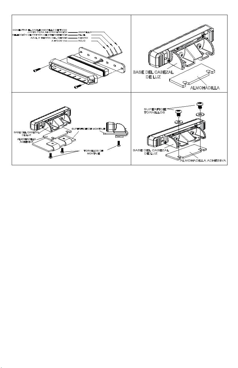
de un vehículo. Las cuatro opciones de montaje (supercie, borde,
autoadhesivo y permanente) y los 30 grados de giro ajustable brindan
exibilidad superior cuando se posicionan las luces para lograr una
capacidad de advertencia óptima. Ambos modelos ofrecen múltiples
patrones de intermitencia y se pueden sincronizar varias unidades
para funcionar simultáneamente o alternadamente entre sí.
Los modelos ED3706 cuentan con 6 LED y están disponibles en un
color o en combinaciones de color dividido* (3 LED de cada color)
con ópticas que brindan una salida de luz en un solo eje. El modelo
ED3712 es una luz de color doble* con 12 LED (6 de cada color)
y está disponible en 7 conguraciones de colores con ópticas que
ofrecen una cobertura más amplia, fuera del eje.
Instrucciones de instalación y operación
LED direccional
* Color dividido = Una la horizontal de LED se divide 50/50 entre los dos
colores (solo una mitad de la luz se puede iluminar en cada color). Color doble
= Dos las horizontales de LED (una de cada color) ocupan el ancho de la luz
(se puede iluminar toda la luz en cada color)
1. Para garantizar su seguridad y la de todos aquellos a los que desea proteger, es importante que exista una adecuada
instalación, así como también una capacitación de los operadores para el uso, el cuidado y el mantenimiento de los
dispositivos de alerta de emergencias.
2. Opere con precaución cuando trabaje con conexiones eléctricas en tensión.
3. El producto deber conectarse a tierra adecuadamente. Una conexión incorrecta o cortocircuito en las conexiones
eléctricas puede ocasionar arcos de alta tensión lo que, a su vez, puede producir heridas o daños a su vehículo y fuego
inclusive.
4. Para un buen desempeño del dispositivo de alerta, es de vital importancia que exista una instalación y una ubicación
adecuadas. Instale este producto de modo que el rendimiento del sistema se maximice y los controles se ubiquen al
alcance del operador, de esta manera éste podrá operar el sistema sin perder el contacto visual de la calzada.
5. No instale el producto o je algún cable en el área de despliegue de la bolsa de aire. Los equipos que se instalen o se
coloquen en el área de despliegue de la bolsa de aire pueden reducir la efectividad de la bolsa, o convertirse en un
proyectil que puede ocasionar heridas e incluso la muerte. Consulte el manual de usuario del vehículo acerca del área
de despliegue de la bolsa de aire. Es responsabilidad del usuario/operador determinar una ubicación adecuada para la
instalación, con el n de garantizar la seguridad de todos los pasajeros dentro del vehículo y evitar particularmente las
potenciales áreas de impacto de la cabeza.
6. Es responsabilidad del operador del vehículo asegurarse de que todas las características del producto funcionen
correctamente durante su operación. Durante su operación, el operador del vehículo debe asegurarse de que la
proyección de las señales de alerta no se encuentre bloqueada por componentes propios del vehículo (es decir, baúles
o puertas abiertas), personas, vehículos u otras obstrucciones.
7. El uso de este o cualquier otro dispositivo de alerta no garantiza que todos los conductores puedan observar o
reaccionar a las señales de advertencia. Nunca subestime el derecho de paso. Es su responsabilidad asegurarse de que
pueda proceder con seguridad antes de ingresar en una intersección, conducir en contra del tráco o a alta velocidad, y
caminar por o alrededor de carriles de circulación.
8. Este equipo debe operarse solo por personal autorizado. El usuario es responsable de comprender y obedecer todas
las leyes con respecto a los dispositivos de señales de alerta. Por lo tanto, el usuario debe revisar todas las leyes y
regulaciones aplicables tanto las correspondientes a la ciudad como las estatales y federales. El fabricante no asume
ninguna responsabilidad por la pérdida como resultado del uso del dispositivo de alerta.
No instale u opere este producto de seguridad a menos que haya leído y comprendido la información de seguridad
que contiene este manual.
¡ADVERTENCIA!
En caso de no instalar ni utilizar este producto conforme a las sugerencias del fabricante se podrían ocasionar daños a la
propiedad, lesiones graves personales o el deceso del usuario y de las personas que se busca proteger.
920-0399-00 Rev. H
¡Importante! Esta unidad es un dispositivo de seguridad y debe conectarse
a su propia alimentación con fusible para garantizar un servicio continuo en el
caso de que falle cualquier otro accesorio eléctrico.
Precaución: Al perforar cualquier supercie del vehículo, asegúrese de
que no haya cables eléctricos, mangueras de combustible, tapicería, etc.
en el área que pudiesen dañarse.
Página 7 de 12
1Cabezal de luz
1Base para múltiples montajes:
Incluye:
2 - Tornillos de chapa de metal
4x15
2 - Arandelas divididas
2 - Tornillos M3.5x10
2 - Arandelas M3
1Almohadilla adhesiva
1Soporte para montaje en borde:
Incluye: 2 - Tornillos M3.5x10
1Bisel de montaje en supercie:
Incluye: 2 - Tornillos de chapa de metal 4x15
1 - Junta de espuma EVA
ÍNDICE:
Tensión de entrada 12 a 24 VCC
Corriente de funcionamiento
ED3706 = 0,9 A a 12 VCC
ED3712 = 1,5 A a 12 VCC
ESPECIFICACIONES: