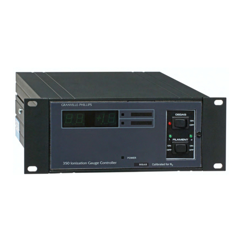
MKS HPS 947 Series User manual

HPS®Series 947
Digital
Convection Enhanced Pirani (CEP)
Vacuum Sensor System
OPERATION AND
MAINTENANCEMANUAL


HPS®ProductsSeries 947 CEP System
SensaVac®Series947
Digital
Convection Enhanced Pirani (CEP)
Vacuum Sensor System
February1999
Part # REV.A

HPS®Products Series 947 CEP System
Part # 947-X-XXX-XX
– __– __ __ __–__ __
Serial # __ __ __ __ __ __
Please fill in these numbers and have
them readily available when calling for
service or additional information.
(The part number can be found on your
packing slip, and the serial number is
located on the back panel of the controller.)
© 1996 by MKS Instruments, Inc. HPS®Division. All rights reserved.
SensaVac is a registered trademark ofMKS Instruments, Inc.
TeflonandVitonareregisteredtrademarks of DuPontCo.
VCR is a registered trademark of Cajon Co.
For more information or literature, contact:
MKS Instruments. HPS®Division, Inc.
5330Sterling Drive
Boulder,CO80301 USA
Phone: 303-449-9861
800-345-1967
FAX: 303-442-6880

HPS®ProductsSeries 947 CEP System
Table of Contents
Table of Contents
Package Contents..................................................................... 1
Symbols Used in this Manual.................................................... 2
Safety Precautions .................................................................... 3
Specifications............................................................................ 5
Controller.......................................................................................... 6
Sensor Tube.................................................................................. 7
Feature and Control Locations .................................................. 8
Typical Applications for the Series 947 CEP System................ 9
About the SensaVac® Series 947 CEP Vacuum Sensor System
................................................................................................ 10
Installing the Series 947 CEP System..................................... 11
CEP Sensor Installation................................................................. 11
Location....................................................................................... 11
Orientation................................................................................... 11
Contamination ............................................................................. 11
Vacuum Connection.................................................................... 11
CEP Controller Installation ....................................................... 12
ControllerMounting.......................................................................12
ConnectingtheSensortotheController .......................................13
ACPowerCord .............................................................................14
FuseReplacement........................................................................14
AccessoryConnector ...................................................................14
Relay Inductive Loads and Arc Suppression ................................15
Operating the Series 947 CEP System ................................... 16
Reading Pressure .......................................................................... 16
Sensor Adjustment...................................................................... 18
Calibrating for Zero and Atmosphere .......................................... 18
Adjusting the Set Points.............................................................. 18
Venting to Atmosphere................................................................ 19
Buffered Analog Output............................................................... 19
Use with Computers ................................................................... 19
HPS®Products Series 947 CEP System
Leak Detection............................................................................ 19
Using the Series 947 CEP System with Other Gases ............. 22
Nitrogen Equivalent Pressure ..................................................... 22
Calibrating for Other Gases ........................................................ 23
Maintaining the Series 947 CEP System ................................ 24
Troubleshooting and Service ...................................................... 24
Cleaning the Series 947 CEP Controller Front Panel ................. 24
Cleaning the CEP Sensor ........................................................... 25
Testing the CEP Sensor ............................................................. 25
Preparing for Bakeout ................................................................. 26
Accessories............................................................................. 27
ProductWarranty..................................................................... 29
Notes....................................................................................... 30
Appendix A: How the Series 947 CEP System Works ..........A.1
Theory of a Thermal Conductivity Sensor .................................A.1
Measurement Limits...................................................................A.1
The Series 947 CEP System Design Overview........................A.2
Bridge Amplifier .......................................................................A.2
Output .....................................................................................A.2
Set Point Relays .....................................................................A.2
Comparator .............................................................................A.2

1
HPS®Products Series 947 CEP System
BeforeunpackingyourSeries947Digital Convection Enhanced Pirani (CEP)
Vacuum Sensor System, check all surfaces of the packing material for
shippingdamage.
Please be sure that your Series 947 CEP System package contains
these items:
1Series 947 CEPController
1 female, 9-pin, subminiature D (D-sub)
Accessory
connector
1powercord
1 SensaVac®Series 947 Digital Convection Enhanced Pirani (CEP)
Vacuum Sensor System User's Manual.
The Series 947 System's CEP Sensor and its connecting cable are sold
separately.Please refer to page 26for necessaryordering information.
If any items are missing from the package, call HPS®Customer
Serviceat1-303-449-9861or1-800-345-1967.
Inspect the Series 947 CEP System for visible evidence of damage. If it
has been damaged in shipping, notify the carrier immediately. Keep all
shipping materials and packaging for claim verification. Do not return the
product to HPS®.
Package Contents

2HPS®ProductsSeries947 CEPSystem
The first two symbols below, located on your Series 947 Controller and/or
Sensor, identify critical safety concerns. They are used throughout this
manual to further define the safety concerns associated with the product.
The last two symbols identify other information in this manual that is
essential to highlight or useful in achieving optimal performance from your
Series 947 CEP System.
CAUTION: Risk of electrical shock.
CAUTION: Refertomanual.
Failure to heed message could result in personal injury or
serious damage to the equipment or both.
Failure to heed message could result in damage to the
equipment.
Informationcallingattentiontoimportantprocedures,
practices, or conditions.
Symbols Used in this Manual

3
HPS®Products Series 947 CEP System
Safety Precautions
Do not use the Series 947 CEP System's Sensor with explosive
gas mixtures or gases that are combustible in air.
If the control circuit fails or an exothermic catalytic reaction occurs at the
sensor platinum wire, the wire could ignite the gas mixture.
When using the Series 947 CEP System with gases other than air
or nitrogen, avoid overpressure to prevent any possibility of
explosion.
Since the Sensor is calibrated for air/nitrogen, the measured pressure of
another gas will differ from its true pressure. Calibrations diverge widely at
higher pressures. Since the different gases are not linearly related, a gas
correctionfactorcouldleadtohazardousoverpressure.Capacitance
manometersand mechanical dialgauges are best suited forhigher pressures.
Refer to page 21 for use with other gases.
In a system which is filled from a pressurized source, install a safety relief
valve or burst disc to safely limit pressure.
The Series 947 CEP Controller contains lethal voltages within the
casing.
Avoid danger of electrical shock. Unplug the power cord before opening the
casing.
Turn off power to the Controller before connecting or
disconnecting a cable to the Sensor.
Connecting or disconnecting cables while the Controller is on may damage
the Sensor.
ProperlygroundtheController.
TheControllerisgroundedthroughtheconductorofthepowercord.Ifthe
protective ground connection is lost, all accessible conductive parts may pose a
risk of electrical shock. Plug the cord into a properly grounded outlet only.
When applying a voltage or current to the ports on the rear of the panel, do
not exceed manufacturer's specifications. Electrical shock may result.
Allow only qualified technicians to service the Series 947 CEP
System.
Users should not remove covers, casings, or plug-in components. Injury may
result. Any part replacement or internal adjustments must be performed by a
qualified technician only.

4HPS®ProductsSeries947 CEPSystem
To prevent damage to the Series 947 CEP Controller, use the
correctlinevoltage.
Use the Controller with the specified line voltage only. Use a fuse of the
correct type, voltage, and current rating. Only qualified personnel should
change line voltage or fuse ratings if required.
Outside of the U.S., use only a detachable cord set having conductors with a
cross-sectionalarea equalto or greater than 0.75 mm2. Powercables should
have agency approval, for example, VDE, Semko, or SEV.
The Series 947 CEP System and all its accessories must be used as
instructed by MKS Instruments, Inc., HPS®Division, to ensure safe
operation. Use or modification of the equipment in a manner not
consistentwithspecificationsmayrendertheproduct'sinherent
protectionuseless.

5
HPS®Products Series 947 CEP System
Specifications
Controller
MeasuringRange 1.0 x 10⁻³ to 1.0 x 10+3 Torr
1.0 to 1.0 x 10+6 microns
1.3 x 10⁻³ to 1.3 x 10+3 mbar
1.3 x 10⁻¹ to 1.3 x 10+5 Pa
UsefulSetPointRange 2.0 x 10⁻³ to 9.9 x 10+2 Torr
2.0 to 9.9 x 10+5 microns
2.7 x 10⁻³ to 1.3 x 10+3 mbar
2.7 x 10⁻¹ to 1.3 x 10+5 Pa
Resolution 1% of decade
OperatingTemperatureRange 5°to 40°C (41°to 104°F)
StorageTemperatureRange -10°to55°C(14°to131°F)
RelativeHumidity 80% maximum for temperatures less
than 31°C, decreasing linearly to
50% maximum at 40°C
Altitude 2000 m maximum
InsulationCoordination
Installation(Overvoltage)CategoryII
,
PollutionDegree2
MainsVoltage Fluctuations not to exceed ±10%
NumberofChannels 1
FrontPanelControls 2nonvolatile, independentrelayset
points; power on-off switch; zero
adjustment;atmosphericadjustment
RelayContactRating SPDT, 1 A @ 24 VAC/DC, resistive
RelayResponse 150 msec maximum
PowerRequirement 90 to 130 VAC, 50/60 Hz
or
210 to 250 VAC, 50/60 Hz
PowerConsumption 9 W

6HPS®ProductsSeries 947CEPSystem
Output Voltage 0.33to5.63 VDC, bufferedanalog,
1 kW maximum output impedance
Fuse Rating, Size T 0.16 A, Ø5 mm x 20 mm
for 90 to 130 VAC;
T 0.063 A, Ø5 mm x 20 mm
for 210 to 250 VAC
Display LED with 2 significant digits
(1leading)and1signedexponent;
red, 3/5"-high,7-segment digits; LED
set point indicators; units shown in
either Torr, mbar, Pascal or microns
ElectronicCasing Aluminum,anodized
Dimensions 3¾" x 7" x 3¾"
(W x D x H) (96 mm x 178 mm x 96 mm)
Size ¼DIN
Weight 2.2 lb (1.0 kg)
CECertification EMC Directive
LowVoltageDirective
*The Controller meets CE mark requirements only if used with a Shielded Sensor.

7
HPS®Products Series 947 CEP System
Design and/or specifications subject to change without notice.
Sensor Tube
CalibrationGas Air/nitrogen
InstallationOrientation Horizontal
only
MaterialsExposedtoVacuum 304 stainless steel, platinum, glass,
nickel
Repeatability 5% of indicated pressure @ Tconst
Internal Volume 2.0 in.3(33.0 cm3) maximum
OperatingTemperatureRange 0°to 50°C (32°to 122°F)
MaximumBakeoutTemperature 200°C(392°F),
100°C(212°F)shielded;
withoutcable,connector/electronics
subassembly,andController
Diameter 1.6 in. (41 mm)
Length 4.4 in. (112 mm)
Typical Weight (with KF 16 Flange) 0.5 lb (0.2 kg)
VacuumConnection KF 16
KF 25
1/8"NPT-M
with ½" compression seal option
8VCR®-F(½")
11/3"CF(non-rotatable)
2¾"CF(non-rotatable)
Ø15.0 mm x 30.0 mm tubing
Ø18.0 mm x 30.0 mm tubing

8HPS®ProductsSeries 947CEPSystem
DigitalLEDDisplay
PowerOn-Off Rocker Switch
View Set Point Push-buttons
Set Point Adjustment Potentiometers
LED Set Point Indicators
AtmosphericAdjustmentPotentiometer
ZeroAdjustmentPotentiometer
PowerCordInletw/FuseHolder
PanelMountingFastenerHoles
Female,9-pin
Gauge
Port
Male, 9-pin
Accessory
Port
Slots(for Optional Mounting Brackets)
Male,9-pin
Gauge
Port
SensorVacuumPort
Controller
Feature and Control Locations
14
13
12
11
1
2
3
4
5
6
7
8
9
10
12
SideView

9
HPS®Products Series 947 CEP System
Typical Applications for the
Series 947 CEP System
Measuringforelineandroughing pressures
generatedby
mechanicalvacuumpumps
Controlling valves and pumps
to automate system pump down
using the relay set points
Sensingabnormalpressure
andtakingappropriatesecurity
measures using the relay set points
Controlling system pressure
usingthe analog output as input to
anautomaticpressurecontroller
Starting or stopping system processes
usingtherelayset points
Measuring pressures of backfilled gases
intherange of
10-3 to10+3Torr
Activating high vacuum sensors
at the high end of their
operatingpressurerange

10 HPS®ProductsSeries 947CEPSystem
About the SensaVac®Series 947
CEPVacuum Sensor System
The Series 947 Convection Enhanced Pirani (CEP) System, together
with itsSensor and connecting cable, provides accurate and reliable
data for processes which need pressure control from 10+3 Torr to 10-3
Torr. It is low in cost and is easy to use.
The CEP Sensor is available with one of several standard fittings for
vacuum connection. The Sensor connects to the Controller with a cable
that has 9-pin D-sub connectors on either end, one male and one
female. The Controller easily mounts into a ¼DIN panel cutout or
stands alone. All controls, even the power switch, are conveniently
located on the front panel, and cable connections are hidden to the rear
of the Controller.
The Series 947 CEP
Controller is useful
either as a small
system controller
or as a module
in more
sophisticated
pressurecontrol
environments.
TheController
featurestwo
standard relay set
points for process
applications.
Thepressurereadout
is a large, easy-to-
read digital display.
LEDs indicate the
status of relay set
points. Set points are
independentlyadjusted
using both a push-button and a potentiometer on the front panel.
The analog output and relay contacts are accessible from the
Accessory
port on the rear panel.
The Sensor can be located away from the Controller using a cable as
long as 500 feet in length.

11
HPS®Products Series 947 CEP System
Installing the
Series 947 CEP System
CEP Sensor Installation
Location
Locate the CEP Sensor where it can measure chamber or manifold pressure.
Install it away from pumps and gas sources and where vibration is minimal to
give the most representative values.
Orientation
The CEP Sensor can
only
be installed horizontally to work effectively in the
convection region. Convection is an effective heat transfer process at
pressures above 200 Torr of nitrogen. Install it in the direction indicated on
the body of the Sensor.
The Sensor is factory calibrated with the vacuum port facing down. At
atmosphere, the calibration may shift as much as 10% if the port is oriented
otherwise. If it is necessary to do so, you should make a calibration
adjustment(seeCalibratingfor Zero andAtmosphere,p.18).
Contamination
Locate and orient the CEP Sensor where contamination is least likely. For
example, if the Sensor is installed directly above a roughing pump, oil vapor
could contaminate the tube's filament wire and cause the calibration to shift.
Install the Sensor with the vacuum port facing down whenever possible to
prevent particulates falling or liquids flowing into it. Using a screen or porous
filter at the port is helpful. Try an HPS®seal and centering ring assembly with
a screen (see Accessories, p. 26).
Vacuum Connection
Standard vacuum interfaces for the CEP Sensor include:
KF 16 flange 11/3" CF flange
KF 25 flange 2 ¾" CF flange
8 VCR®-F (½") fitting Ø15 mm x 30 mm tubing
1/8" NPT-M fitting Ø18 mm x 30 mm tubing
with ½" compression seal
To fit the KF 16 port to a KF 10 port, use an HPS®adaptive centering ring
(seeAccessories,p.26).

12 HPS®ProductsSeries 947CEPSystem
To fit the Sensor with the 1/8" NPT, do not use the case for tightening. The
Sensor's vacuum tubing has 9/16" hex flats for tightening. Wrap a layer of
Teflon®tape on the threads of the tubing, in the direction of installation, to
ensurealeak-freeseal.
Instead of the NPT fitting, you may opt to use the ½" O-ring compression
seal against the vacuum tubing above the thread, but the O-ring seal cannot
be used for positive pressure applications.
Ensure a solid electrical connection between the Sensor
and the grounded vacuum system to shield the tube
elementfromexternalelectromagneticsources.In
applications which the System will be exposed to large
voltage fluctuations, install a centering ring with a screen,
and then ground the screen and tubing.
CEP Controller Installation
ControllerMounting
The Series 947 CEP Controller is designed for either panel mounting or for
stand-aloneuse.Regardlessofthemethodyou choose, assure adequate
ventilation to the Controller with at least a ½of an inch left open above and
belowtheperforatedpanels.
An optional hardware kit is also available for mounting the Controller into a
standard ¼DIN cutout in a panel up to 3/16-inch thick (see Accessories,
p.26). A dimensioned illustration below shows the required cutout. Leave at
least 3 inches of clearance behind the Controller to accommodate the
connectorsandcables.
Mount the Controller into the panel by slipping it through the cutout from the
front. Slide the panel mounting brackets into the slots on either side of the
Controllerfrom the rear, and secure them withthe thumbscrewsprovided.

13
HPS®Products Series 947 CEP System
1
5
6
9
Pin numbers
Any length up to 500 feet
TUBE
Female, 9-pin d-sub connector 24 AWG, 6 conductor
(3 twisted pairs)
Connect drain wire
to metal hood at
both ends
Drain wire
Mount 4 screwlocks in
connector hood assemblies for
strain relief
Customizing the sensor cable
CONTROLLER
Male, 9-pin D-sub connector
1
5
6
9
1,6
5,9
3
4
8
7
2
1,6
5,9
3
4
8
7
Adhesive backed rubber feet for bench top use are provided with the
mounting kit. Remove the adhesive backing from each foot and apply one to
each corner of the aluminum bottom surface.
ConnectingtheSensortothe Controller
A sensor cable with 9-pin D-sub connectors (see Accessories, p.26) is
required for operation but is purchased separately from the CEP System.
When exerting excessive stress on the cable, use separate strain relief to
preventdamagetotheSensoror Controller. Cables are availableinstandard
lengths of 10, 25, 50, and 100 feet and in custom lengths up to 500 feet.
Connect the cable to the rear of the Controller at the
Gauge
port. Tighten the
connector jackscrews into the mating screw locks to ensure proper electrical
connection and to prevent stress on the connectors.
TurnofftheControllerbefore connecting or disconnecting the
cable from the Sensor or Controller.

14 HPS®ProductsSeries 947CEPSystem
In applications for which special cables are required, i.e., where the
connection must be routed through restrictive barriers or through a
conduit, customize the cable using the figure shown below. For short
lengths, any cable wired straight through, e.g., pin 1 to pin 1, will
suffice. For longer lengths, a cable with three twisted pairs and an
overall shield is recommended. Use a D-sub connector with
jackscrews for strain relief in all applications.
ACPowerCord
The Series 947 CEP System includes a standard, 120 VAC, 50/60 Hz power
cordwith a female IEC-320connector.
If the available power source or connection is different, use only a detachable
cord set with conductors that have a cross-sectional area equal to or greater
than 0.75 mm2. The power cable should be approved by a qualified agency
such as VDE, Semko, or SEV.
FuseReplacement
The Series 947 CEP System has a combined fuse holder and power outlet
located on the rear panel of the Controller. Replace the fuse with the
followingsteps.
1. Unplug the power cord from its outlet.
2. Snap out the fuse holder drawer.
3. Replace the fuse(s) with one of the following time-lag fuses:
T 0.16 A (Ø5 mm x 20 mm) –90 to 130 VAC
T 0.063 A (Ø5 mm x 20 mm) –210 to 250 VAC.
4. Close and secure the fuse holder drawer.
AccessoryConnector
Relay set point contacts and the analog output voltage can be accessed from
the
Accessory
port on the rear panel of the Controller. A connector kit to mate
to the port is provided. The figure and chart below identify the pin functions of
the
Accessory
port.
Pin Description
1 Set point relay 1 - normally closed contact
2 Set point relay 1 - normally open contact
3 Set point relay 2 - common
4 Notused
5 Analogoutputvoltage (+)
6 Set point relay 1 - common
7 Set point relay 2 - normally closed contact
8 Set point relay 2 - normally open contact
9 Analogoutputvoltage(-)
9-pin Accessory port
15
9
6
Table of contents
Other MKS Controllers manuals
Popular Controllers manuals by other brands

Sonnet
Sonnet Configuration tool and utilities installation manual

RocketRAID
RocketRAID 2680 installation guide

RADEMACHER
RADEMACHER 9470-4 manual

Resol
Resol DeltaSol ES manual

CentriPro
CentriPro AQUAVAR CPC Installation and operation manual

Regada
Regada MO 3 Installation, service and maintenance instructions