EVCO S.p.A. | EV3 Mix | 104XXXMA3.00
www.evco.it
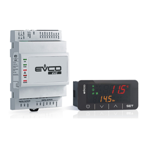
EV3 Mix - Inverter e Interfaccia Basic / Plus
1/2
CONNESSIONI ELETTRICHE
PERICOLO
RISCHIO DI SHOCK ELETTRICO, ESPLOSIONE O ARCO ELETTRICO
• Solo il personale adeguatamente formato, che ha familiarità ed è in grado di
comprendere il contenuto del manuale e di tutta la documentazione relativa, è
autorizzato a operare su e con questo inverter. Inoltre, il personale deve aver seguito
corsi di sicurezza e deve saper riconoscere ed evitare i pericoli implicati. L'installazione,
la regolazione e la manutenzione devono essere eseguite esclusivamente da personale
qualificato.
• Diversi componenti del prodotto, compresi i circuiti stampati, funzionano a tensione pericolosa.
• Utilizzare esclusivamente apparecchiature di misurazione e attrezzi isolati
elettricamente e opportunamente tarati.
• Non aprire, smontare, riparare o modificare il prodotto.
• Prima di maneggiare il prodotto, indossare tutti i dispositivi di protezione individuali
necessari.
• Non esporre l'apparecchiatura a sostanze liquide o agenti chimici.
• Prima di applicare tensione all'inverter:
• Verificare che l'intervento sia terminato e che nessuna parte dell'impianto possa
generare pericoli.
• Se i morsetti di ingresso dell'alimentazione di rete e i morsetti di uscita del motore
sono stati messi a terra e circuitati, eliminare la terra e i cortocircuiti in tali morsetti.
• Verificare che tutte le apparecchiature dispongano di una corretta messa a terra.
• Verificare che tutti gli elementi di protezione, come coperchi, sportelli e griglie, siano
installati e/o chiusi.
• Verificare tutti i collegamenti di cablaggio.
IL MANCATO RISPETTO DI QUESTE ISTRUZIONI PROVOCHERÀ MORTE O
GRAVI INFORTUNI.
PERICOLO
RISCHIO DI SHOCK ELETTRICO E INCENDIO
• Non utilizzare l'apparecchiatura con carichi superiori a quelli indicati nei dati tecnici.
• Non eccedere i range di temperatura e umidità indicati nei dati tecnici.
IL MANCATO RISPETTO DI QUESTE ISTRUZIONI PROVOCHERÀ MORTE O
GRAVI INFORTUNI.
Questa apparecchiatura è stata progettata per funzionare in luoghi non pericolosi e con
l’esclusione di applicazioni che generino, o possano potenzialmente generare, atmosfere
pericolose. Installare questa apparecchiatura esclusivamente in zone e applicazioni
notoriamente sempre esenti da atmosfere pericolose.
PERICOLO
RISCHIO DI ESPLOSIONE
• Installare ed utilizzare questa apparecchiatura solo in luoghi non a rischio.
• Non installare né utilizzare questa apparecchiatura in applicazioni in grado di generare
atmosfere pericolose, quali le applicazioni che impiegano refrigeranti infiammabili.
IL MANCATO RISPETTO DI QUESTE ISTRUZIONI PROVOCHERÀ MORTE O
GRAVI INFORTUNI.
AVVERTIMENTO
FUNZIONAMENTO ANOMALO DELL'APPARECCHIATURA
• Eseguire il cablaggio con attenzione conformemente ai requisiti in materia di
compatibilità elettromagnetica.
• Non mettere in funzione il prodotto con impostazioni o dati ignoti o errati.
• Eseguire un test di messa in funzione completo.
• Verificare che il cablaggio sia corretto per le impostazioni.
• Usare cavi schermati per tutti cavi di segnali di I/O e di comunicazione.
• Usare cavi a doppia schermatura per i cablaggi del motore.
• Ridurre il più possibile la lunghezza dei collegamenti ed evitare di avvolgerli intorno a
parti collegate elettricamente.
• I cavi di segnale (comunicazione e relative alimentazioni), i cavi di potenza e di
alimentazione dello strumento devono essere instradati separatamente.
• Prima di applicare l’alimentazione elettrica, verificare tutti i collegamenti del cablaggio.
• Non collegare fili a dei morsetti non utilizzati e/o a morsetti che riportano la dicitura
“Nessuna connessione “(N.C.)”.
IL MANCATO RISPETTO DI QUESTE ISTRUZIONI PUÒ PROVOCARE MORTE,
GRAVI INFORTUNI O DANNI ALLE APPARECCHIATURE.
DIMENSIONI
Inverter
59 (2.32)
40 (1.57)
0.8 (0.03)
154 (6.06)
95 (3.74)
27 (1.06) 100 (3.94)
Interfaccia Basic/Plus
33 (1.30)
75 (2.95)
69 (2.71)
59 (2.32)
mm (in.)
INSTALLAZIONE
Inverter
L'installazione dell'inverter è prevista tramite una staffa angolare (non in dotazione).
Modelli 0,75 kW
Modelli 1,5 kW / 2,2 kW
Installare l'inverter rispettando la distanza minima in ogni lato di 40 mm (1.57 in.). Rispettare
la distanza tra base d'appoggio e dissipatore di almeno 10 mm (0.39 in.).
40 (1.57)
40 (1.57)
Interfaccia Basic/Plus
71
(2.7
9)
29 (1.14)
mm (in.)
SCHEMA DI CONNESSIONE
Inverter
Inverter
Ingresso
Alimentazione
+ Vdc-GND
UVWPE
COM NC CNO
LNPE
ID 2ID 2ID1
RS-485 Ingressi
N.C. Uscita
TERMINALI
LFASE - Ingresso alimentazione ID 3 Ingresso digitale 3 - Reset allarmi
NNEUTRO - Ingresso alimentazione COM Comune ingressi digitali
PE TERRA - Ingresso alimentazione NC
Normalmente chiuso uscita relè allarme
UUscita per comando motore CComune uscita
relè allarme
VUscita per comando motore NO
Normalmente aperto uscita relè allarme
WUscita per comando motore
+
Ingresso seriale RS-485+
PE Collegamento a terra motore -Ingresso seriale RS-485-
ID 1 Ingresso digitale 1- Stop/Run GND Ingresso GND seriale RS-485
ID 2
Ingresso digitale 2 - Termica Motore
Vdc Alimentazione 12 Vdc
Interfaccia Basic/Plus
c
-
+
TERMINALI
21 Collegamento alimentazione 12 Vdc da Inverter
22 Collegamento seriale RS-485- con Inverter
23 Collegamento seriale RS-485+ con Inverter
24 Collegamento seriale RS-485 GND con Inverter
Collegamento Interfaccia / Inverter
Vdc
Interfaccia Basic/Plus
Inverter
21 22 23 24
B A GND
+ Vdc-GND
DATI TECNICI
Condizioni operative ambientali: -10...55 °C (14...131 °F) 10…90 % RH non condensante
Condizioni di trasporto e immagazzinamento: -20...60 °C (-4...140 °F) 10…90 % RH non condensante
Altitudine: Massimo 1000 m (3.280 ft)
Classe di inquinamento: 2
Grado di protezione: IP00
Categoria di sovratensione: II
Alimentazione: 230 Vac, ±10%, 50/60 Hz
Corrente di ingresso (rms): 0,75 kW: 5 A
1,5 kW: 10 A
2,2 kW: 15 A
Corrente di uscita (rms): 0,75 kW: 3,3 A
1,5 kW: 6,3 A
2,2 kW: 8,8 A
Metodo di raffreddamento: Modelli 0,75kW: Ventilazione naturale
Altri modelli: Ventilazione forzata
ALTRE INFORMAZIONI TECNICHE - INVERTER
Proprietà degli ingressi (SELV)
Ingressi digitali: 3 ingressi digitali
Proprietà delle uscite
Uscite digitali: 1 Uscita relè 5 A a 250 Vac
Uscita motore: 0...230 Vac, 3 ph a Vin = 230 Vac
Frequenza portante: 5...16 kHz
Sovraccarico nominale: Massimo 150% per 60 secondi
Frequenza d'uscita: 0...100 Hz
Proprietà delle seriali di comunicazione (SELV)
Seriale RS-485:
1 Seriale RS-485 MODBUS RTU Slave opto-isolata
rinforzata per collegamento con interfaccia Basic/Plus.
Massimo baudrate: 38400 bps - Lunghezza massima del
cavo: 1,5 m (4.9 ft.)
CONFORMITÀ
CE secondo direttiva EN61800-3 ed EN61800-5-1 in categoria C2
SPECIFICHE TECNICHE - INTERFACCE BASIC/PLUS
Il prodotto è conforme alle seguenti norme armonizzate: EN60730-1 e EN60730-2-9
Costruzione del dispositivo: Dispositivo incorporato
Scopo del dispositivo : Dispositivo di comando di funzionamento
Tipo di azione: 1
Grado di inquinamento: 2
Categoria di sovratensione : I
Tensione impulsiva nominale: 330 V
Alimentazione : 12 Vdc ±10%
Consumo : 0,7 W
Condizioni operative ambientali: 0 ... 55 °C (32 ... 131 °F) 10 … 90 % RH non condensante)
Condizioni di trasporto e immagazzinamento: -25 ... 70 °C (-13 ... 158 °F) 10 … 90 % RH non condensante
Classe del software: A
Protezione frontale ambientale: IP65
ALTRE INFORMAZIONI TECNICHE - INTERFACCE BASIC/PLUS
Proprietà delle seriali di comunicazione (SELV)
Seriale RS-485:
1 Seriale RS-485 MODBUS RTU Master
INTERFACCIA UTENTE
Tasti
Descrizione tasti
Toccare...
•Perentrareincongurazionemodalitàciclodirotazioneautomatico.
•Per avviare o mettere in pausa un ciclo di rotazione;
•Per confermare valori;
•2 secondi: Arresta ciclo di rotazione.
•Perentrareincongurazionemodalitàciclodirotazionemanuale;
•Per scorre i valori verso il basso;
•Durante ciclo: decrementa la velocità.
•Per scorre i valori verso l'alto;
•Durante ciclo: incrementa la velocità.
Icone
Basic Plus
Descrizione icone Modello
Accesa fissa: - In configurazione fase 1
- Fase 1 del ciclo attiva Basic/Plus
Accesa fissa: - In configurazione fase 2
- Fase 2 del ciclo attiva Basic/Plus
Accesa fissa: - In configurazione fase 3
- Fase 3 del ciclo attiva Plus
Accesa fissa: - In configurazione fase 4
- Fase 4 del ciclo attiva Plus
Accesa fissa: - In configurazione fase 5
- Fase 5 del ciclo attiva Plus
Accesa fissa: - In configurazione fase 6
- Fase 6 del ciclo attiva Plus
Lampeggiante:
Funzionamento motore inverso Basic/Plus
Accesa fissa: Modalità ciclo rotazione manuale attiva Basic/Plus
Accesa fissa: Valore visualizzato in minuti Basic/Plus
Accesa fissa: Valore visualizzato in secondi Basic/Plus
Accesa fissa: Ciclo di rotazione attivo
Basic/PlusLampeggiante: Ciclo di rotazione in pausa
Spenta: Ciclo di rotazione non attivo
Accesa fissa: Motore non in movimento Basic/Plus
Lampeggiante:
Allarme attivo (si visualizza il codice di allarme) Plus
Accese sequenziali: Ciclo di rotazione attivo Plus
Lampeggianti: Ciclo di rotazione in pausa Plus
Spente: Ciclo di rotazione non attivo Plus
Accesa fissa: Modalità automatica attiva Plus
Accesa fissa: Valore visualizzato in tempo (minuti o secondi) Plus
Lampeggiante: Ciclo di rotazione in pausa Plus
Non usate
TABELLA PARAMETRI UTENTE
Par.
Descrizione UM Range
Default modelli [kW]
PW
0.75 1.5 2.2
Gruppo CONTROLLO A··
A03 Selezione tipo di controllo applicato al motore.
1= Scalare; 2= Vettoriale. NOTA: Contattare
supporto tecnico EVCO per impostazione A03 = 2.
- 1/2 1 1 1 E
Gruppo VELOCITÀ B··
B02 Rampa di accelerazione. Tempo necessario per
arrivare dalla velocità 0 rpm alla velocità nominale s
0.2 ... 200.0
3.0 3.0 3.0 O
B03 Rampa decelerazione. Tempo necessario per
arrivare dalla velocità nominale alla velocità 0 rpm. s
0.2 ... 200.0
5.0 5.0 5.0 O
B04 Velocità massima del motore (1). rpm 0 ... 12000 1500 1500 1500 O
B05 Velocità minima del motore (1). rpm 0 ... 12000 300 300 300 O
Gruppo INGRESSI/USCITE C··
C10 Funzione uscita 1. 0= Riservato; 1= Inverter ready;
2= Inverter in run; 3= Inverter in allarme;
4= Gestita da Seriale RS-485; 11...20 = Riservati.
- 0 ... 20 3 3 3 O
Gruppo MOTORE E··
E01 Corrente nominale motore (2). A 0.1 ... S601 2.9 5.5 7.9 O
E02 Tensione nominale motore (2). V 50 ... 400 230 230 230 O
E03 Frequenza nominale motore (2). Hz 0 ... 100 50 50 50 O
E04 Numero coppie polari (2). - 1 ... 8 2 2 2 O
E09 Boost motore. Percentuale di sovra tensione
applicata all'avvio del motore. % 0 ... 25 5 5 5 O
E10 Tensione motore. Percentuale di tensione massima
applicata al motore rispetto a quella nominale. % 10 ... 112 100 100 100 E
E11 Sovraccarico motore. Percentuale di sovraccarico
al motore che l'inverter consente per un tempo
impostato dal parametro E12.
% 0 ... 50 50 50 50 E
E12 Tempo massimo di sovraccarico. s 0 ... 60 30 30 30 E
E29 Selezione frequenza della portante PWM. KHz 5 ... 16 5 5 5 O
E34
Sensibilità allarme mancanza fase motore. Indica la
percentuale di sensibilità dell'allarme di mancanza fase
motore. 0= disabilitato; 100 = massima sensibilità.
% 0 ... 100 0 0 0 O
Gruppo MOTORE G··
G40 Gestione ripartenza ciclo. 0= Ripartenza sicura;
1= Ripartenza veloce. - 0/1 1 1 1
E/O
(1)
I limiti minimi e massimi sono calcolati in funzione del numero di coppie polari del motore ovvero tra 5 e 100 Hz;
(2)
Parametro dipendente dai dati di targa del motore;
ALLARMI
Cod.
Descrizione N. lamp.
LED rosso Causa Risoluzione allarme
UV Allarme sotto
tensione
1
Il valore di tensione del dispositivo
è sceso al di sotto di 200 V
• Reset allarme funzione
AUTORESET quando abilitata;
• Reset allarme da ingresso ID3
OV Allarme sovra
tensione
2
Il valore di tensione del dispositivo
ha superato il valore di 420 V
OC Allarme
sovracorrente
3 Il dispositivo ha superato il
valore massimo di corrente:
0.75 kW 1.5 kW 2.2 kW
5.0 A 9.4 A 13.2 A
OL Allarme
sovraccarico
4 La quantità di energia secondo
la logica I²t ha superato il
valore del parametro E10 per
il tempo E11
BT
Allarme
sovratemperatura
scheda elettronica
5 Il dispositivo ha raggiunto
e superato la temperatura
massima di 90 °C
• L’allarme si resetta
automaticamente se temp.
motore < 90 °C - 10 °C (50 °F);
• Reset allarme da ingresso ID3
OT
Allarme
sovratemperatura
dissipatore
6 Il motore ha raggiunto e
superato la temperatura
massima di 90 °C
• L’allarme si resetta
automaticamente se temp.
motore < 90 °C - 10 °C (50 °F);
• Reset allarme da ingresso ID3
EP Allarme eeprom
dati
8 La struttura dati non è integra • Valori di default ripristinati
automaticamente;
Ricongurareiparametri;
• Reset allarme da ingresso ID3
TO Allarme timeout
comunicazione
9 Comunicazione MODBUS
interrotta
• Vericarelaconnessione;
• Reset allarme da ingresso ID3
US Allarme utente 10 Allarme associato ad un
ingresso
• Eliminare la causa dell’allarme;
• Reset allarme da ingresso ID3
PS Allarme Phase
Lose
12 • Motore non collegato
correttamente
• Sensibilità E34 non corretta
•
Vericarecablaggioalimentazione;
• ModicareparametroE34;
• Reset allarme da ingresso ID3
MT Allarme termica
motore
13
Allarme associato ad un
ingresso (ID2 = termica motore)
• Eliminare la causa dell’allarme;
• Reset allarme da ingresso ID3
MS Allarme stallo
motore
14 Motore non gira
correttamente con algoritmo
vettoriale
• Controllare parametri E01...E19
;
•
Reset allarme da ingresso ID3;
•
Contattare supporto tecnico EVCO
Declinazione di responsabilità
La presente documentazione è proprietà esclusiva di EVCO. Contiene la descrizione generale e/o le
caratteristiche tecniche per le prestazioni dei prodotti qui contenuti. Questa documentazione non è
destinata a e non deve essere utilizzata per determinare l'adeguatezza o l'affidabilità di questi prodotti
relativamente alle specifiche applicazioni dell'utente. Ogni utente o specialista di integrazione deve
condurre le proprie analisi complete e appropriate del rischio, effettuare la valutazione e il test dei
prodotti in relazione all'uso o all'applicazione specifica.
Né EVCO né qualunque associata o filiale deve essere tenuta responsabile o perseguibile per il cattivo
uso delle informazioni ivi contenute. Gli utenti possono inviarci commenti e suggerimenti per migliorare o
correggere questa pubblicazione.
EVCO adotta una politica di continuo sviluppo. Pertanto EVCO si riserva il diritto di effettuare modifiche e
miglioramenti a qualsiasi prodotto descritto nel presente documento senza previo preavviso.
I dati tecnici presenti nel manuale possono subire modifiche senza obbligo di preavviso.
CONSIDERA L'AMBIENTE
Si prega di leggere e conservare il documento
SMALTIMENTO
Il dispositivo deve essere smaltito secondo le normative locali in merito alla
raccolta delle apparecchiature elettriche ed elettroniche.
