A-Neuvideo ANI-HDROTATE User manual

AUDIO / VIDEO MANUFACTURER
ANI-HDROTATE
HDMI VIDEO WALL ROTATION PROCESSOR
INSTRUCTION MANUAL
A-NeuVideo.com
Frisco, Texas 75036

SAFETY INFORMATION
1. To ensure the best results from this product, please read this manual and all other documentation before operating your equipment.
Retain all documentation for future reference.
2. Follow all instructions printed on unit chassis for proper operation.
3. To reduce the risk of re, do not spill water or other liquids into or on the unit, or operate the unit while standing in liquid.
4. Make sure power outlets conform to the power requirements listed on the back of the unit. Keep unit protected from rain, water and
excessive moisture.
5. Do not attempt to clean the unit with chemical solvents or aerosol cleaners, as this may damage the unit. Dust with a clean dry cloth.
6. Do not use the unit if the electrical power cord is frayed or broken. The power supply cords should be routed so that they are not
likely to be walked on or pinched by items placed upon or against them, paying particular attention to cords and plugs, convenience
receptacles, and the point where they exit from the appliance.
7. Do not force switched or external connections in any way. They should all connect easily, without needing to be forced.
8. Always operate the unit with the AC ground wire connected to the electrical system ground. Precautions should be taken so that the
means of grounding of a piece of equipment is not defeated.
9. AC voltage must be correct and the same as that printed on the rear of the unit. Damage caused by connection to improper AC
voltage is not covered by any warranty.
10. Turn power off and disconnect unit from AC current before making connections.
11. Never hold a power switch in the “ON” position.
12. This unit should be installed in a cool dry place, away from sources of excessive heat, vibration, dust, moisture and cold. Do not use
the unit near stoves, heat registers, radiators, or other heat producing devices.
13. Do not block fan intake or exhaust ports. Do not operate equipment on a surface or in an environment which may impede the normal
ow of air around the unit, such as a bed, rug, carpet, or completely enclosed rack. If the unit is used in an extremely dusty or smoky
environment, the unit should be periodically “blown free” of foreign dust and matter.
14. To reduce the risk of electric shock, do not remove the cover. There are no user serviceable parts inside. Refer all servicing to
qualied service personnel. There are no user serviceable parts inside.
15. When moving the unit, disconnect input ports rst, then remove the power cable; nally, disconnect the interconnecting cables to
other devices.
16. Do not drive the inputs with a signal level greater than that required to drive equipment to full output.
17. The equipment power cord should be unplugged from the outlet when left unused for a long period of time.
18. Save the carton and packing material even if the equipment has arrived in good condition. Should you ever need to ship the unit,
use only the original factory packing.
19. Service Information Equipment should be serviced by qualied service personnel when:
A. The power supply cord or the plug has been damaged.
B. Objects have fallen, or liquid has been spilled into the equipment.
C. The equipment has been exposed to rain.
D. The equipment does not appear to operate normally, or exhibits a marked change in performance.
E. The equipment has been dropped, or the enclosure damaged.
THIS SAFETY INFORMATION IS OF A GENERAL NATURE AND MAY BE SUPERSEDED BY INSTRUCTIONS CONTAINED WITHIN THIS MANUAL.

TABLE OF CONTENTS
ANEUVIDEO
1
CONTENTS
PACKAGE CONTENTS / APPLICATIONS /
SYSTEM REQUIREMENTS .........................................................1
INTRODUCTION............................................................................2
FEATURES & SPECIFICATIONS .................................................. 2
FRONT PANEL ..............................................................................3
BACK PANEL ................................................................................4
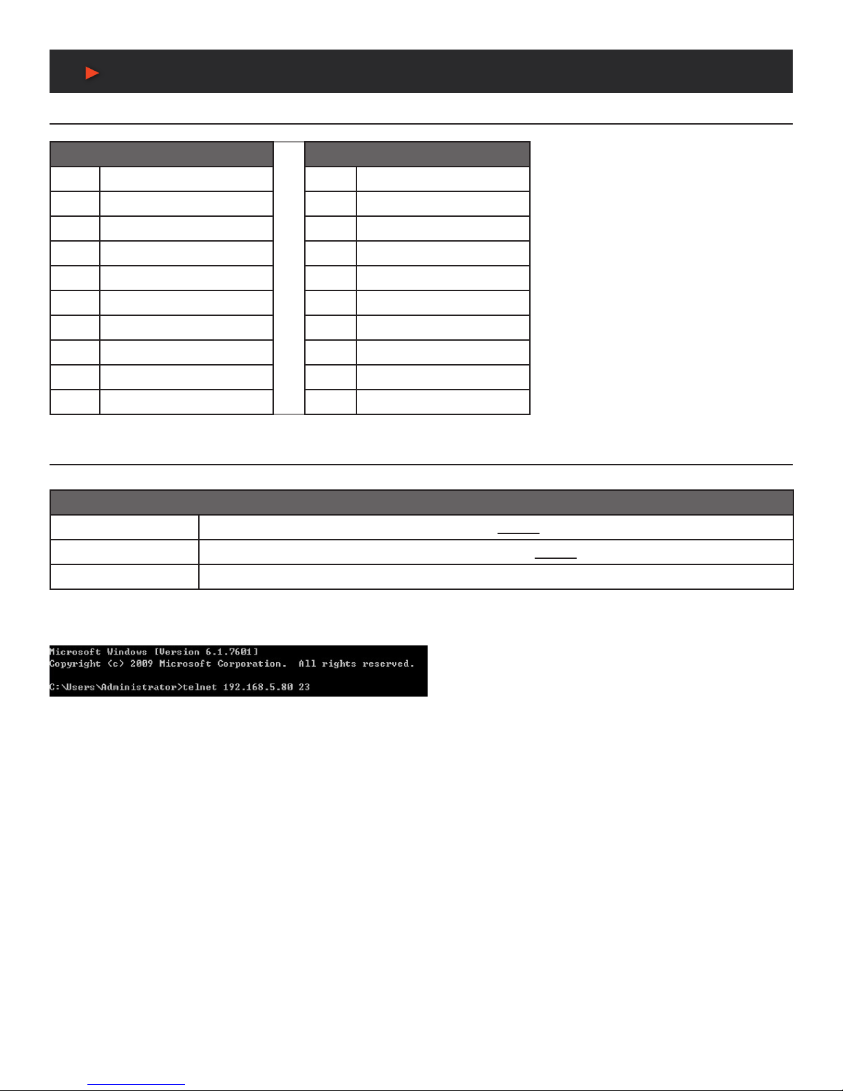
RS-232 & TELNET CONTROL .......................................................5
RS-232 & TELNET COMMANDS ...................................................6
VIDEO WALL CONTROL SOFTWARE ........................................10
VIDEO /AUDIO / CABLE SPECIFICATIONS .................................18
CONNECTION DIAGRAM ..........................................................19
Dear Customer
Thank you for purchasing this product. For optimum performance
and safety, please read these instructions carefully before
connecting, operating or adjusting this product. Please keep this
manual for future reference.
PACKAGE CONTENTS
Before attempting to use this unit, please check the packaging and
make sure the following items are contained in the shipping carton:
• ANI-HDROTATE HDMI Video Wall Rotation Processor
• 5V/2.6A DC Power Adapter
• Shockproof Feet (Set of 4)
• Users Guide
APPLICATIONS
• Public Commercial Displays
• Demo Room Displays
• Hotel Lobby Information Displays
• Live Public Events
SYSTEM REQUIREMENTS
• HDMI source equipment such as media players, video game
consoles or set-top boxes.
• HDMI receiving equipment such as HDTVs, monitors or
audio ampliers.
SAFETY PRECAUTIONS
Please read all instructions before attempting to unpack, install or
operate this equipment and before connecting the power supply.
Please keep the following in mind as you unpack and install this
equipment:
• Always follow basic safety precautions to reduce the risk of re,
electrical shock and injury to persons.
• To prevent re or shock hazard, do not expose the unit to rain,
moisture or install this product near water.
• Never spill liquid of any kind on or into this product.
• Never push an object of any kind into this product through any
openings or empty slots in the unit, as you may damage parts
inside the unit.
• Do not attach the power supply cabling to building surfaces.
• Use only the supplied power supply unit (PSU). Do not use the
PSU if it is damaged.
• Do not allow anything to rest on the power cabling or allow any
weight to be placed upon it or any person walk on it.
• To protect the unit from overheating, do not block any vents or
openings in the unit housing that provide ventilation and allow for
sufcient space for air to circulate around the unit.
DISCLAIMERS
The information in this manual has been carefully checked and
is believed to be accurate. We assume no responsibility for any
infringements of patents or other rights of third parties which may
result from its use.
We assume no responsibility for any inaccuracies that may be
contained in this document. We make no commitment to update or
to keep current the information contained in this document.
We reserve the right to make improvements to this document and/
or product at any time and without notice.
COPYRIGHT NOTICE
No part of this document may be reproduced, transmitted,
transcribed, stored in a retrieval system, or any of its part translated
into any language or computer le, in any form or by any means
— electronic, mechanical, magnetic, optical, chemical, manual, or
otherwise — without the express written permission and consent.
© Copyright 2019. All Rights Reserved.
Version 1.0 DEC 2018
TRADEMARK ACKNOWLEDGMENTS
All products or service names mentioned in this document may be
trademarks of the companies with which they are associated.

2
FEATURES & SPECIFICATIONS
INTRODUCTION
The ANI-HDROTATE HDMI Video Wall Rotation Processor is capable of scaling and rotating the input source to nearly any angle and size
desired. Its the ideal solution for presenting sources across the unique video display arrangements often found in commercial displays,
control rooms, or classrooms. HDMI Input and output resolutions up to 1080p@60Hz with LPCM audio up to 7.1 channels at 192kHz
are supported. In Rotation Mode the output is locked to 1080p, but video latency is only 1 to 2 frames and the unit is capable of scaling
and rotating the source, with an accuracy of 1°, as required. In Scaler Mode, the unit can scale to a selection of output resolutions, up to
1080p@60Hz as well as apply video mirror, ip and freeze effects to the output.
By combining multiple units with an HDMI splitter or matrix it is possible to create fantastically varied arrangements of rotated displays for
large video wall applications. This is perfect for creating distinct and eye-catching advertising or promotional displays limited only by your
imagination. Conguring these large video walls is made simple by use of our Video Wall PC application, allowing the user to visually lay
out and congure the entire video wall at one time in a graphical WYSIWYG user interface. A number of common video wall arrangement
presets are included with the software by default to make it possible to get started quickly. Basic control of the unit is provided by front panel
controls with an informational OSD. Complete control of the unit is accomplished by use of Telnet, RS-232 or the Video Wall PC software.
This product has a 3 year warranty.
FEATURES
• HDMI 1.3 & HDCP 1.4 compliant
• (1) HDMI input and (1) HDMI output
• Input and output supports HD resolutions up to 1080p@60Hz
• Supports pass-through of audio formats including LPCM 2.0/5.1/7.1, Bitstream, and HD Bitstream
• Only 1 to 2 frames of video latency
• Supports horizontal/vertical video warping with zooming in/out and 360 degree display rotation in 1° increments (Rotation Mode)
• Video mirror, ip, and freeze (Scaler Mode)
• Wide variety of video adjustments, including: contrast, brightness, hue, sharpness, aspect ratio
• Custom EDID management
• Basic control of the unit is provided by front panel controls with an informational OSD
• Complete control of the unit is accomplished by use of Telnet, RS- 232 or the Video Wall PC software
SPECIFICATIONS
• HDMI Bandwidth: 340MHz/10.2Gbps
• Input Port: (1) HDMI
• Output Port:(1) HDMI
• Control Ports: RS-232 (DE-9) & IP Control (RJ45)
• Baud Rate: 19200bps
• Power Supply: 5V/2.6 DC (US/EU standards, CE/FCC/UL certied)
• ESD Protection: Human Body Model:
• ±8kV (Air Discharge)
• ±4kV (Contact Discharge)
• Dimensions (WxDXH): 9.1 x 1 x 4.25 in (231.5x25x108mm) [Case Only] / 9.1 x 1 x 4.6 in (231.5x25x117mm) [All Inclusive]
• Weight: 1.4 lb/652g
• Chassis Material: Metal (Steel)
• Silkscreen Color: Black
• Operating Temperature: 0˚C–40˚C/32˚F–104˚F
• Storage Temperature: -20˚C–60˚C/-4˚F–140˚F
• Relative Humidity: 20–90% RH (Non-condensing)
• Power Consumption: 5.9W
As product improvements are continuous, specications are subject to change without notice.
ANEUVIDEO

3
PANEL DESCRIPTIONS
FRONT PANEL
qSERVICE PORT: This port is used for logo upload, EDID upload and rmware updates.
wPOWER LED: This LED will illuminate to indicate the unit is on and receiving power.
eMODE BUTTON: Press the button to toggle between Scaler Mode and Rotation Mode.
rSCALE LED: This LED will be illuminated when the unit is in Scaler Mode.
tROTATE LED: This LED will be illuminated when the unit is in Rotation Mode.
yASPECT RATIO & WARPING ON/OFF BUTTON:
• Scaler Mode: Press to switch between the available output aspect ratios (Full, 4:3, 16:9, 16:10).
• Rotation Mode: Press to turn Warping Mode on or off.
uAUDIO MUTE BUTTON: Press to mute or unmute the audio output.
iVIDEO STILL & 360° ROTATE BUTTON
• Scaler Mode: Press to freeze the video output.
Note: Audio will continue to play while the video is frozen.
• Rotation Mode: Press to enter automatic 360° rotation mode and toggle through the available rotation directions and speeds (slow
counterclockwise, slow clockwise, fast counterclockwise, fast clockwise, stop).
Note: Activating 360° rotation will disable Warping Mode.
oOSD INFO. & 45° ROTATE BUTTON
• Scaler Mode: Press to display information about the unit on the OSD including details about video, audio and Ethernet.
• Rotation Mode: Press to rotate the output video in 45 degree increments. Press and hold this button to display the OSD Info screen.
Note: Activating 45° rotation will disable Warping Mode.
ANEUVIDEO

4
PANEL DESCRIPTIONS
BACK PANEL
qOUT PORT: Connect to an HDMI TV, monitor or amplier for digital video and audio output.
wIN PORT: Connect to HDMI source equipment such as a media player, game console or set-top box.
eRS-232 PORT: Connect directly to a PC, laptop or other serial control device to send RS-232 commands to control the unit.
rCONTROL PORT: Connect directly, or through a network switch, to your PC/laptop to control the unit via Telnet or the control software.
tDC 5V PORT: Plug the 5V DC power adapter into this port and connect it to an AC wall outlet for power.
ANEUVIDEO

5
RS-232 & Telnet Control
RS-232 Protocol
SIGNAL GENERATOR REMOTE CONTROL
PIN ASSIGNMENT PIN ASSIGNMENT
1 NC 1 NC
2 TxD 2 RxD
3 RxD 3 TxD
4 NC 4 NC
5 GND 5 GND
6 NC 6 NC
7 NC 7 NC
8 NC 8 NC
9 NC 9 NC
Telnet Control
Before attempting to use Telnet control, please ensure that both the unit and the PC/laptop are connected to the same active network.
To Access Telnet
In Windows XP Click Start, type “cmd” in the search eld, and press ENTER.
In Windows 7 Click Start > Run, type “cmd” in the search eld, and press ENTER.
In Mac OS X Click Go > Applications > Utilities > Terminal.
Once in the Command Line Interface (CLI) type “telnet” followed by the IP address of the unit (and the port number if it is non-standard)
and then hit “Enter”. This will connect us to the unit we wish to control.
NOTES: The default IP address is 192.168.1.50. If the IP address is changed then the IP address required for Telnet access will also
change accordingly.
ANEUVIDEO
Baud Rate: 115200bps
Data Bits: 8
Parity: None
Flow Control: None
Stop Bit: 1

6
RS-232 & Telnet Commands
COMMAND DESCRIPTION AND PARAMETERS
GET FW VER 8Show the unit’s current rmware version.
SET FACTORY DEFAULT 8Reset the unit to the factory defaults.
SET IN A EDID N1 8Set the EDID to be used by the HDMI input.
Available values for N1:
1 [FHD/2CH]
2 [FHD/MCH]
3 [User EDID]
15 [Sink EDID]
GET IN A EDID 8Show the EDID currently being used by the HDMI input.
SET OUT A MUTE N1 8Enable or disable audio/video mute on the HDMI output.
Available values for N1:
ON [A/V Mute enabled]
OFF [A/V Mute disabled]
GET OUT A MUTE 8Show the current audio/video mute state of the HDMI output.
SET OUT A AUDIO MUTE N1 8Enable or disable the audio-only mute on the HDMI output.
Available values for N1:
ON [Mute enabled]
OFF [Mute disabled]
GET OUT A AUDIO MUTE 8Show the current audio mute state of the HDMI output.
GET OUT A SYNC STATUS 8Show the current sync state of the HDMI output.
SET OUT A OSD INFO N1 8Enable or disable the info OSD for the HDMI output.
Available values for N1:
ON [Enable OSD]
OFF [Disable OSD]
GET OUT A OSD INFO 8Show the current info OSD state for the HDMI output.
SET OUT A OSD INFO TIMEOUT N1 8Set the info OSD’s timeout value for the HDMI output (in seconds).
N1 = 0 ~ 100 [Timeout length]
GET OUT A OSD INFO TIMEOUT 8Show the current info OSD’s timeout value for the HDMI output.
SET OUT A OSD INFO VPOSITION N1 8Set the vertical position of the OSD on the HDMI output.
N1 = 0 ~ 100 [Vertical position]
GET OUT A OSD INFO VPOSITION 8Show the current vertical position of the OSD on the HDMI output.
SET OUT A OSD INFO HPOSITION N1 8Set the horizontal position of the OSD on the HDMI output.
N1 = 0 ~ 100 [Horizontal position]
GET OUT A OSD INFO HPOSITION 8Show the current horizontal position of the OSD on the HDMI output.
GET MAC ADDR 8Show the unit’s MAC address.
SET IP MODE N1 8Set the IP address assignment mode.
Available values for N1:
0 [Static IP mode]
1 [DHCP mode]
GET IP MODE 8Show the current IP address assignment mode.
GET IPCONFIG 8Show the unit’s current IP conguration information.
SET IP ADDR N1 8Set the unit’s static IP address.
N1 = x.x.x.x [x = 0 ~ 255, IP address]
GET IP ADDR 8Show the unit’s current IP address.
ANEUVIDEO

7
RS-232 & Telnet Commands
COMMAND DESCRIPTION AND PARAMETERS
SET NETMASK N1 8Set the unit’s netmask address.
N1 = x.x.x.x [x = 0 ~ 255, Netmask]
GET NETMASK 8Show the unit’s current netmask.
SET GATEWAY N1 8Set the unit’s gateway address.
N1 = x.x.x.x [x = 0 ~ 255, Gateway]
GET GATEWAY 8Show the unit’s current gateway address.
SET TELNET PORT N1 8Set the unit’s Telnet access port.
N1 = 0 ~ 65535 [Port number]
GET TELNET PORT 8Show the unit’s current access Telnet port.
USB UPDATE MCU 8Begins the rmware update process and searches for a rmware le on a thumb drive in
the USB port.
Note: The firmware’s filename must be “FIRMWARE.BIN”.
USB UPDATE EDID 8Upload a new User EDID from a thumb drive in the USB port.
Note: The EDID’s filename must be “USEREDID.BIN”.
USB UPDATE BMP 8Upload a new User Bitmap from a thumb drive in the USB port.
Note: The logo filename must be “LOGO.BMP” and the resolution must be 1920x1080
(or less) with 256 colors.
SET WARPING ENABLE N1 8Enable or disable Warping Mode.
Available values for N1:
ON [Warping enabled]
OFF [Warping disabled]
Note: Rotation Mode only.
GET WARPING ENABLE 8Show the current Warping Mode state.
SET SCALING A MODE N1 8Set the unit’s output scaler mode.
Available values for N1:
1 [Rotation Mode]
2 [Scaler Mode]
GET SCALING A MODE 8Show the unit’s current output scaler mode.
SET ROT360 A MODE N1 8Control the unit’s 360° automated rotation demonstration mode.
Available values for N1:
0 [Stop rotation]
1 [Rotate counterclockwise slowly]
2 [Rotate clockwise slowly]
3 [Rotate counterclockwise quickly]
4 [Rotate clockwise quickly]
Note: Rotation Mode only. Automatically disables Warping.
GET ROT360 A MODE 8Show the 360° automated rotation demonstration mode’s current state.
SET ROT45N A MODE N1 8Set a xed rotation angle for the output image.
Available values for N1:
0 [Rotate 0°]
1 [Rotate 45°]
2 [Rotate 90°]
3 [Rotate 135°]
4 [Rotate 180°]
5 [Rotate 225°]
6 [Rotate 270°]
7 [Rotate 315°]
Note: Rotation Mode only. Automatically disables Warping.
GET ROT45N A MODE 8Show the current xed rotation angle setting.
ANEUVIDEO

8
RS-232 & Telnet Commands
COMMAND DESCRIPTION AND PARAMETERS
SET OUT A TIMING N1 8Set the output resolution to use for the HDMI output using the universal timing number.
Available values for N1:
0 [Native]
4 [480p@60Hz]
6 [720p@60Hz]
10 [1080p@60Hz]
11 [576p@50Hz]
12 [720p@50Hz]
14 [1080p@50Hz]
16 [1080p@24Hz]
17 [1080p@25Hz]
19 [1080p@30Hz]
416 [1024x768@60Hz]
417 [1280x800@60Hz]
419 [1280x1024@60Hz]
420 [1366x768@60Hz]
423 [1440x900@60Hz]
424 [1600x900@60Hz (RB)]
425 [1600x1200@60Hz]
426 [1680x1050@60Hz]
430 [1920x1200@60Hz]
Note: Scaler Mode only.
GET OUT A TIMING 8Show the universal timing number of the current resolution used by the HDMI output.
GET OUT A TIMING STRING 8Show the universal timing number and description string of the current resolution used
by the HDMI output.
SET IN A CONTRAST N1 8Set the contrast level of the video source.
N1 = 0 ~ 100 [Contrast level]
Note: Scaler Mode only.
GET IN A CONTRAST 8Show the current contrast level of the video source.
SET IN A BRIGHTNESS N1 8Set the brightness level of the video source.
N1 = 0 ~ 100 [Brightness level]
Note: Scaler Mode only.
GET IN A BRIGHTNESS 8Show the current brightness level of the video source.
SET IN A HUE N1 8Set the hue value of the video source.
N1 = 0 ~ 100 [Hue value]
Note: Scaler Mode only.
GET IN A HUE 8Show the current hue value of the video source.
SET IN A SHARPNESS N1 8Set the sharpness level of the video source.
N1 = 0 ~ 20 [Sharpness level]
Note: Scaler Mode only.
GET IN A SHARPNESS 8Show the current sharpness level of the video source.
SET OUT A ASPECT RATIO N1 8Set the aspect ratio of the video shown on the HDMI output.
Available values for N1:
1 [Full screen]
2 [4:3]
3 [16:9]
4 [16:10]
Note: Scaler Mode only.
GET OUT A ASPECT RATIO 8Show the current aspect ratio setting for the video shown on the HDMI output.
ANEUVIDEO

9
RS-232 & Telnet Commands
COMMAND DESCRIPTION AND PARAMETERS
SET IN A TEMPERATURE N1 8Set the color temperature of the video source.
Available values for N1:
1 [6500K]
2 [9300K]
Note: Scaler Mode only.
GET IN A TEMPERATURE 8Show the current color temperature setting for the video source.
SET IN A FLIP N1 8Enable or disable horizontally ipping the video source.
Available values for N1:
ON [Enable horizontal ip]
OFF [Disable horizontal ip]
Note: Scaler Mode only.
GET IN A FLIP 8Show the current horizontal ip state of the video source.
SET IN A IMAGE STILL N1 8Enable or disable freezing the video source.
Available values for N1:
ON [Enable video freeze]
OFF [Disable video freeze]
Note: Scaler Mode only.
GET IN A IMAGE STILL 8Show the current video freeze state of the video source.
SET OUT A OSD TEXT N1 8Set a text overlay string for display over the video output.
N1 = {String} [32 characters max]
GET OUT A OSD TEXT 8Show the current text overlay string content.
SET OUT A TEXT OVERLAY N1 8Enable or disable display of the custom text overlay string.
Available values for N1:
ON [Enable text overlay]
OFF [Disable text overlay]
Note: Scaler Mode only.
GET OUT A TEXT OVERLAY 8Show the current state of the custom text overlay display.
SET OUT A OVERLAY HPOS N1 8Set the horizontal position of the custom text overlay on the HDMI output.
N1 = 0 ~ 100 [Horizontal position]
GET OUT A OVERLAY HPOS 8Show the current horizontal position of the custom text overlay on the HDMI output.
SET OUT A OVERLAY VPOS N1 8Set the vertical position of the custom text overlay on the HDMI output.
N1 = 0 ~ 100 [Vertical position]
GET OUT A OVERLAY VPOS 8Show the current vertical position of the custom text overlay on the HDMI output.
SET OUT A OSD BITMAP N1 8Enable or disable display of the User Bitmap image.
Available values for N1:
ON [Enable bitmap display]
OFF [Disable bitmap display]
Note: Scaler Mode only.
GET OUT A OSD BITMAP 8Show the current state of the User Bitmap image display.
SET OUT A BITMAP HPOS N1 8Set the horizontal position of the User Bitmap on the HDMI output.
N1 = 0 ~ 100 [Horizontal position]
GET OUT A BITMAP HPOS 8Show the current horizontal position of the User Bitmap on the HDMI output.
SET OUT A BITMAP VPOS N1 8Set the vertical position of the User Bitmap on the HDMI output.
N1 = 0 ~ 100 [Vertical position]
GET OUT A BITMAP VPOS 8Show the current vertical position of the User Bitmap on the HDMI output.
Note: Commands will not be executed unless followed by a carriage return. Commands are not case-sensitive.
ANEUVIDEO

10
VIDEO WALL CONTROL SOFTWARE
The Video Wall Control software provides complete control over the Video Wall Rotation Processor via Ethernet or RS-232. This software
can scan the local network, as well as any RS-232 connections on the PC, for controllable units to add to the current video wall grouping.
Multiple video wall congurations can be stored in the software for quick local recall, or the congurations can be exported as a le for
use in other video wall deployments.
In addition to video wall design, creation, and positioning, this
software can also be used to congure the scaler mode of the
unit, if needed.
Software Operation
Please obtain the “Video Wall Control” software from our website for download and save it in a directory where you can easily nd it.
Ensure that all the units you wish to control have been powered on and that they are all connected to the same network as your laptop/
PC. Start the software by double clicking on the *.exe le to start the Video Wall Control software.
By default, when the software starts, the layout will be empty. Dummy displays may be added to/removed from the layout using the
“+”/“−” buttons in the “Unit” section if there are no live units available for control and the user wishes to visualize different display
arrangements. To add physical units to the layout, perform a “Search”.
Note: This software is only compatible with Windows 7 or later PCs.
Video Wall Unit Search
By clicking on the “Search” button at the top-right corner of the window, all Video Wall Rotation Processors that are located on the local
network or are directly connected via RS-232 can automatically discovered. Each detected unit can then be added to the current video
wall layout and assigned a unique ID number.
1. SEARCH BUTTON:Click on the “Search” button to open the
Unit Selection Window. All detected units on the local network
as well as all available local serial ports will be listed in the “All
Units” section. After all units have been selected and arranged,
click on the “OK” button to add them to the layout.
Note: Units connected via RS-232 can’t be directly detected,
so all available serial ports will be listed, even if they do not
currently have a connected unit.
■ ALL UNITS LIST: All detected units on the local network
as well as all available local serial ports are listed here. All
detected units are identied by their IP address. If additional
units are added to the network after the window is opened,
click “Refresh” to detect them. Selecting a Unit (or serial port)
and then clicking the right arrow button ( ) will place them in
the Selected Units window in the order they are added. The
Ethernet details of each detected unit may also be changed
by clicking on the associated details icon ( ).
ANEUVIDEO

11
VIDEO WALL CONTROL SOFTWARE
■ SELECTED UNITS: All selected units will appear here with an ID number indicating their order to be added to the layout. If you wish
to re-order the units, type new ID numbers next to each unit and click “Arrange”. To remove an individual unit from the list, click the
“X” next to it’s name. To remove all units, click the “Clear” button.
After all desired displays have been added to the layout, each display must be connected to so that they may be controlled. If some
displays that need to be a part of the layout are not currently available for connection, dummy monitors may be added in their place.
Displays that are no longer a part of the layout may also be disconnected, or removed completely. Each display can be connected or
disconnected individually, or as a group.
2. CONNECT BUTTON: Clicking the “Connect” button will
activate the software’s connection to all discovered units,
allowing control and conguration of those units. To connect to
only a single unit, right click on the unit’s number and select
“Connect”.
3. DISCONNECT BUTTON: If you want to ensure that no
additional settings are sent to the units, click the “Disconnect”
button and all units will be disconnected from the software. To
disconnect a single unit, right click on the unit’s number and
select “Disconnect”.
Note: Disconnected units will still be shown in the layout, but
the “Get”, “Set”, and “Setting” functions will not be available.
4. +/− BUTTONS: To add dummy units (displays with no physical
unit currently connected) to a layout, click the “+” button. To
completely remove both real and dummy units from a layout,
select the unit to remove and then click the “−” button.
Basic Unit Settings & Configuration
The basic conguration and settings for each connected unit can be set by selecting the unit to congure from the “Unit” section and then
clicking on the “Setting” button in the upper-left “Common” section of the window. The operational mode of the unit (Rotate Mode or
Scaler Mode) may be set here, as well as the Ethernet, I/O, and mode- specic image features. To exit the setting conguration tabs and
return to the layout mode, click on the “Layout” button in the upper- left “Common” section of the window.
Note: Some configuration options are not available in both modes.
The “General” tab provides control over the network conguration, and provides a way to initiate a rmware update or perform a factory
reset. This tab provides the same options in both operational modes.
1. SYSTEM SETUP: Displays the current rmware version and
provides options to update the rmware or perform a factory
reset on the unit.
■ UPDATE FW BUTTON: Provides a way to update the unit’s
rmware. Insert a USB thumb drive, with a valid rmware le
(*.bin format) in the root directory, into the unit’s USB service
port then click the “Update FW” button. After the update is
complete the unit will automatically reboot.
■ Factory Reset Button: Selecting this will reset the unit’s
settings back to their factory defaults.
2. NETWORK CONFIGURATION: The IP Address, Netmask
and Gateway can be set manually, or DHCP can be enabled for
automatic IP Conguration if your local network supports it. Click
on “Apply” to conrm and activate any changes made to these
settings. To return these settings to their factory defaults, click
on the “Default” button.
Note: If the IP address is changed then the IP address required
for Software or Telnet access will also change accordingly.
ANEUVIDEO

12
VIDEO WALL CONTROL SOFTWARE
Rotation Mode Configuration
The “I/O” tab in Rotation Mode provides control over input and output functions such as EDID selection, audio/video mute, OSD
Information, and custom graphics overlay. To return these settings to their factory defaults, click on the “Default” button. The “General”
tab provides control over the network conguration, and provides a way to initiate a rmware update or perform a factory reset. This tab
provides the same options in both operational modes.
1. EDID MODE: Select the preferred EDID for the unit to use
from the dropdown menu (FHD 2CH, FHD MCH, User, and
Sink).
2. EDID UPDATE: To upload a custom User EDID, insert a USB
thumb drive, with a valid EDID le named “USEREDID.BIN” in
the root directory, into the unit’s USB service port then click the
“Update” button.
3. AV MUTE: Enables or disables the audio/video mute function.
When enabled, video output will be black, and audio will be
muted.
4. AUDIO MUTE: Enabled or disables the audio mute function.
When enabled, the audio output will be muted.
5. OSD INFO: The OSD Info On/Off selector both shows the
current OSD Info state and provides a control to manually
activate it. When “On” is manually selected the OSD Info will
show on the output until the set timeout value has expired then
it will revert to “Off”.
6. OSD INFO TIMEOUT AND OFFSET: The OSD Info timeout value (in seconds) and horizontal and vertical position may be set here.
7. IMAGE OVERLAY DISPLAY: Enables or disables the custom image overlay feature.
Note: Enabling OSD Info will automatically disable the Image Overlay.
8. IMAGE OVERLAY UPDATE: To upload a custom overlay image, insert a USB thumb drive, with a valid graphics le named “LOGO.
BMP” (1920x1080 max resolution, 8-bit color) in the root directory, into the unit’s USB service port then click the “Update” button.
9. IMAGE OVERLAY POSITIONING: Set the horizontal and vertical position of the upper-left corner of the custom overlay image.
The “Image” tab in Rotation Mode provides control over the automatic 360° rotation mode as well as the 45° xed screen rotation mode.
To return these settings to their factory defaults, click on the “Default” button.
1. AUTOMATIC 360° ROTATION MODE: Allows activation
of the automatic 360° rotation mode. Select the speed and
direction from the dropdown menu (slow counter-clockwise,
slow clockwise, fast counter-clockwise, fast clockwise, stop).
2. FIXED 45° ROTATION ANGLE MODE: Allows rotating the
source image to xed, 45°, angles. Select the preferred rotation
angle from the dropdown menu.
ANEUVIDEO

13
VIDEO WALL CONTROL SOFTWARE
Scaler Mode Configuration
The “I/O” tab in Scaler Mode provides control over input and output functions such as EDID selection, audio/video mute, OSD Information,
customized text overlay, and customized graphics overlay. To return these settings to their factory defaults, click on the “Default” button.
1. EDID MODE: Select the preferred EDID for the unit to use
from the dropdown menu (FHD 2CH, FHD MCH, User, and
Sink).
2. EDID UPDATE: To upload a custom User EDID, insert a USB
thumb drive, with a valid EDID le named “USEREDID.BIN” in
the root directory, into the unit’s USB service port then click the
“Update” button.
3. AV MUTE: Enables or disables the audio/video mute function.
When enabled, video output will be black, and audio will be
muted.
4. AUDIO MUTE: Enabled or disables the audio mute function.
When enabled, the audio output will be muted.
5. OSD INFO: The OSD Info On/Off selector both shows the
current OSD Info state and provides a control to manually
activate it. When “On” is manually selected the OSD Info will
show on the output until the set timeout value has expired then
it will revert to “Off”.
6. OSD INFO TIMEOUT AND OFFSET: The OSD Info timeout value (in seconds) and horizontal and vertical position may be set here.
7. TEXT OVERLAY DISPLAY: Enables or disables the custom text overlay feature.
Note: Enabling OSD Info or Image Overlay will automatically disable the Custom Text Overlay.
8. TEXT OVERLAY CONTENT: Type the text to display when the Custom Text Overlay is active. The text string can be up to 32 characters long.
9. CUSTOM TEXT OVERLAY POSITIONING: Set the horizontal and vertical position of the custom text overlay.
10. IMAGE OVERLAY DISPLAY: Enables or disables the custom image overlay feature.
Note: Enabling OSD Info or Custom Text Overlay will automatically disable the Image Overlay.
11. IMAGE OVERLAY UPDATE: To upload a custom overlay image, insert a USB thumb drive, with a valid graphics le named “LOGO.
BMP” (1920x1080 max resolution, 8-bit color) in the root directory, into the unit’s USB service port then click the “Update” button.
12. IMAGE OVERLAY POSITIONING: Set the horizontal and vertical position of the upper-left corner of the custom overlay image.
The “Image” tab in Scaler Mode provides control over the output resolution and aspect ratio, horizontal ip and video freeze features, as
well as multiple video color and quality settings. To return these settings to their factory defaults, click on the “Default” button.
1. OUTPUT RESOLUTION: Selects the output resolution
to use in Scaler mode. Selecting “Native” will make the unit
automatically select an output resolution based on the detected
EDID of the connected display.
2. ASPECT RATIO: Selects the aspect ratio to use for the scaled
output. “Full” stretches the source to ll the output resolution,
regardless of the original aspect ratio. The “4:3”, “16:9”, and
“16:10” options force the source to output at the specied
aspect ratio relative to the currently selected output resolution.
3. HORIZONTAL FLIP: When enabled, ips the scaled output
horizontally.
4. VIDEO FREEZE: When enabled, freezes the scaled video
output.
Note: While the output is frozen, audio will continue to play
normally.
5. COLOR TEMPERATURE: Provides control over the color temperature of the scaled output image.
6. BRIGHTNESS: Provides control over the overall brightness of the scaled output image.
7. CONTRAST: Provides control over the overall contrast of the scaled output image.
8. HUE: Provides control over the hue shift of the scaled output image.
9. SHARPNESS: Provides control over the amount of sharpness processing to apply to the scaled output image.
ANEUVIDEO

14
VIDEO WALL CONTROL SOFTWARE
Pre-Defined Video Wall Layouts
The position, size and angle of the display connected to each unit is set in the Layout window when in Rotation Mode. If you are currently
in the Setting window, clicking on the “Layout” button in the upper- left “Common” section of the window will switch back to the Layout
window and activate Rotation mode.
The outline of the layout window represents the source video (1920x1080 pixels) and each display must be placed within this space,
without exceeding the edges (not including bezel size, if active). Each display contains a number which matches the ID number of the unit
that is connected to it and the size/position of each display (listed to the left) is measured in pixels relative to its size/position within the
layout space. Pre-dened layouts do not include bezel compensation.
Note: Video wall configuration and warping is not available in Scaler Mode.
This control software provides a number of common, pre-dened,
video wall congurations which can be selected and easily
applied to any connected units. All pre-dened congurations
are designed around video walls containing 4 displays.
1. SELECTING PRE-DEFINED LAYOUTS: Select any of the
provided pre-dened layouts from the right-hand scroll bar. After
selecting a new layout, you must conrm that you wish to leave
the current layout.
Note: It is not possible to save changes to the pre-defined
layouts. Switching to a new layout will remove any changes
made to the current layout.
■ AVAILABLE PRE-DEFINED LAYOUTS: After conrming
the preferred layout, select all of the units involved in the
video wall from the “Unit” section at the top of the window
and then click on the “Set” button in the bottom-right corner
of the window to upload the new layout conguration to all
selected units. After clicking “Set”, the units will take a few
seconds to fully update with the new conguration.
ANEUVIDEO

15
VIDEO WALL CONTROL SOFTWARE
Customized Video Wall Layouts
The position, size and angle of the display connected to each unit is set in the Layout window when in Rotation Mode. If you are currently
in the Setting window, clicking on the “Layout” button in the upper- left “Common” section of the window will switch back to the Layout
window and activate Rotation mode.
The outline of the layout window represents the source video (1920x1080 pixels) and each display must be placed within this space,
without exceeding the edges (not including bezel size, if active). Each display contains a number which matches the ID number of the
unit that is connected to it and the size/position of each display (listed to the left) is measured in pixels relative to its size/position within
the layout space. When a bezel measurement is used, the display width/ height measurement should be the total measurement of the
screen plus the bezel.
Note: Video wall configuration and warping is not available in Scaler Mode.
This control software provides a number of common, pre-
dened, video wall congurations, however in most cases
a customized layout will be needed. Custom layouts
are created by selecting a layout to use as a basis, and
then right-clicking on the layout’s selection button and
selecting “New” from the dropdown. You then provide a
name for the new layout and click “OK” to generate it.
Custom layouts are colored differently to make them easy
to identify.
The Unit information area on the left shows all of the relevant
details of the currently selected display. You may freely reposition
or resize any of the displays by simply clicking on them and
dragging them around the layout space, or by typing numbers
directly into the Unit information area. If bezel measurements
are to be used, the display width/height measurement should
be the total measurement of the screen plus the bezel. After
arranging the layout to approximately match the arrangement of
the real displays, select all of the units involved in the video wall
from the “Unit” section at the top of the window and then click
on the “Set” button in the Unit information section to upload
the new layout conguration to all selected units. After clicking
“Set”, the units will take a few seconds to fully update with the
new conguration. In most cases it will take multiple adjustment
and tweaking passes to perfectly match the physical layout.
It is recommended to periodically save the modications that have been made to the current layout by right clicking on the layout and
selecting “Update”. This will save the changes to the layout, so that they are not lost if you close the software, or change to another
layout.
Note: Making changes to a layout and then switching to a new layout without updating the layout will cause those changes to be lost.
ANEUVIDEO

16
VIDEO WALL CONTROL SOFTWARE
1. UNIT INFORMATION AND DETAILS: This section
displays all of the relevant position, dimension, and
orientation details of the selected unit/ display.
Note: Only one unit’s details will be displayed if multiple
units are currently selected.
■ ID: The ID number of the currently selected unit/display.
■ DIMENSIONS: Displays the current values for the pixel
position of the top/left corner of the un-rotated display
as well as the current width and height in pixels. After
changing any of these values, press the enter key to
commit the change to the layout.
Note: If the bezel values are set to 0, the height and width
values should only be the measurement of the video panel
within the display. However, if bezel values are being used,
these dimensions represent the size of the entire physical
display (including the bezel).
■ KEEP ASPECT RATIO: Enabled or disables forcing the current aspect ratio to be maintained when the display is resized either by
typing a new value, or by mouse-dragging a corner of the display in the layout.
■ ANGLE: Displays the current rotation angle of the selected display in degrees. After changing this value, press the enter key to
commit the change to the layout.
■ BEZEL: Displays the current bezel measurements, in pixels, for the selected display and allows for their modication. The bezel
is represented in the layout by a darkened rectangle around the viewable portion of the display. After changing this value, press the
enter key to commit the change to the layout.
Note: Bezel measurements are optional. Bezel values subtract from the entered horizontal and vertical measurements of the display
and reduce the size of the viewable portion of the display in the layout window.
2. GET BUTTON: Downloads the current layout settings from all selected unit(s) into the software.
3. SET BUTTON: Uploads the current layout to all selected unit(s).
4. WARPING ON/OFF BUTTONS: Enables or disables warping on the currently selected unit(s). When warping is disabled, the complete
source video will display normally, lling the display.
5. CUSTOM LAYOUT SELECTION RIGHT-CLICK MENU: Right clicking on any custom layout button brings up a menu of functions that
can be performed on that layout.
■ NEW: Opens the “New Layout” window and allows for the creation of a new custom layout based on the current layout.
■ RENAME: Brings up a window allowing for the selected layout to be renamed.
■ UPDATE: Updates the selected layout with the data in the currently live layout.
■ DELETE: Deletes the selected layout.
Multi-Zone Video Wall Layouts
Though this unit’s input is limited to a maximum resolution of
1080p, it is possible to generate large, exible, video walls
from 4K, or larger, sources by using a traditional 4K+ capable
video wall splitter product with each output of the video wall
splitter generating a 1080p block of video which is then further
distributed to each group of Video Wall Rotation Processors.
Note: It is not possible for a display to be used in more than one
zone at a time, or cross zone borders.
The Zone feature makes managing, and visualizing, this special
arrangement of displays easier. Simply click on the “Zone”
button to launch the Zone Source Setup window. Select the
number of horizontal and vertical zones needed. The total
effective resolution of all zones together is displayed at the
bottom of the window. For example, a 2x2 zone arrangement
would be used if
ANEUVIDEO

17
VIDEO WALL CONTROL SOFTWARE
the original source (before being split) is 4K (3840x2180). Click “OK” to accept the new zone conguration and return to the main layout
window. To arrange the displays used in a specic zone, select the zone from the dropdown and then add the displays that belong to that
zone (via the “Search” function or the “+” button).
1. ZONE BUTTON: Click this to launch the Zone Source Setup window.
2. ZONE SELECTION: This dropdown selects the zone to view or modify.
3. ZONE GRID COLUMN: Sets the number of zones, horizontally, within the full layout.
4. ZONE GRID ROW: Sets the number of zones, vertically, within the full layout.
5. BACKGROUND LOAD: Click this button to load a graphic image to use as a background for the video wall(s) to help visualize the effect
of the whole layout on the source video.
6. BACKGROUND CLEAR: Click this button to remove the background image.
ConFIguration Export/Import
The Conguration and File sections of the main window provide
ways to save/load populated layout congurations as well as to
export/ import congurations/layouts to a le on your local PC. A
saved layout conguration includes unit connection information
as well as display orientation.
1. CONFIGURATION: This section provides a way to load,
save, or clear populated layout congurations.
■ NEW BUTTON: Completely clears all displays from the
currently viewed layout edit window.
Note: Only displays and their unit connection details are
cleared. Layouts saved to the right-side selection bar are
unaffected.
■ LOAD BUTTON: Load a previously saved layout
conguration.
■ SAVE BUTTON: Save the currently viewed layout, including
unit connection information as well as display orientation.
Note: Using the same name as a previously saved
configuration will overwrite it.
2. FILE: This section provides a way to export saved layouts and
congurations to a le on the local PC, or to import previously
saved layouts and congurations.
Note: Exported configurations and layouts are stored as
protected *.zip files and cannot be opened for direct editing.
■ IMPORT BUTTON: Click this button to import a saved
layout or conguration from a le (*.zip format) located on the
local PC.
■ EXPORT BUTTON: Click this button to open the export
dropdown.
– EXPORT CURRENT LAYOUT: Exports the currently
viewed layout to a le on the local PC.
– EXPORT SELECTED LAYOUT: Select a layout, from all
available custom user layouts, to save it to a le on the
local PC.
– EXPORT CURRENT CONFIGURATION: Exports the
current layout’s conguration to a le on the local PC.
– EXPORT SELECTED CONFIGURATION: Select a
conguration, from all available stored congurations, to
save it to a le on the local PC.
ANEUVIDEO

18
Video / audio / cable Specifications
Video Specifications Audio Specifications
SCALER MODE
SUPPORTED RESOLUTIONS (HZ) INPUT OUTPUT
640x480@60/72/75/85 x
800x600@56/60/72/75/85 x
1024x768@60/70/75/85 60
1280x768@60/75 x
1280x800@60 60
1280x960@60 x
1280x1024@60/75 60
1360x768@60 60
1366x768@60 x
1400x1050@60 x
1440x900@60 60
1600x900@60 (RB) x
1600x1200@60 x
1680x1050@60 x
1920x1200@60 (RB) 60
720x576i@50
720x576p@50 50
1280x720p@50/59.94/60 50/60
1920x1080i@50/59.94/60 x
1920x1080p@50/59.94/60 50/60
Note: Rotation mode only supports 1080p@24/25/30/50/60 input and output.
The output refresh rate will always match the input refresh rate.
ANEUVIDEO
HDMI INPUT/OUTPUT
LPCM
Max Channels 8 Channels
Sampling Rate (kHz) 32, 44.1, 48, 88.2, 96, 176.4, 192
BITSTREAM
Supported Formats Standard & High-Denition
cable Specifications
HDMI CABLE LENGTH 1080P
LPCM 8-BIT 12-BIT
Input 16 ft/5m 16 ft/5m
Output 16 ft/5m 16 ft/5m
Table of contents
Other A-Neuvideo Computer Hardware manuals