A-Neuvideo ANI-8WP User manual

AUDIO / VIDEO MANUFACTURER
ANI-8WP
(8) Button Wall Plate Control Keypad
INSTRUCTION MANUAL
A-NeuVideo.com
Frisco, Texas 75034
(469) 277-7606

SAFETY INFORMATION
1. To ensure the best results from this product, please read this manual and all other documentation before operating your equipment.
Retain all documentation for future reference.
2. Follow all instructions printed on unit chassis for proper operation.
3. To reduce the risk of re, do not spill water or other liquids into or on the unit, or operate the unit while standing in liquid.
4. Make sure power outlets conform to the power requirements listed on the back of the unit. Keep unit protected from rain, water and
excessive moisture.
5. Do not attempt to clean the unit with chemical solvents or aerosol cleaners, as this may damage the unit. Dust with a clean dry cloth.
6. Do not use the unit if the electrical power cord is frayed or broken. The power supply cords should be routed so that they are not
likely to be walked on or pinched by items placed upon or against them, paying particular attention to cords and plugs, convenience
receptacles, and the point where they exit from the appliance.
7. Do not force switched or external connections in any way. They should all connect easily, without needing to be forced.
8. Always operate the unit with the AC ground wire connected to the electrical system ground. Precautions should be taken so that the
means of grounding of a piece of equipment is not defeated.
9. AC voltage must be correct and the same as that printed on the rear of the unit. Damage caused by connection to improper AC
voltage is not covered by any warranty.
10. Turn power off and disconnect unit from AC current before making connections.
11. Never hold a power switch in the “ON” position.
12. This unit should be installed in a cool dry place, away from sources of excessive heat, vibration, dust, moisture and cold. Do not use
the unit near stoves, heat registers, radiators, or other heat producing devices.
13. Do not block fan intake or exhaust ports. Do not operate equipment on a surface or in an environment which may impede the normal
ow of air around the unit, such as a bed, rug, carpet, or completely enclosed rack. If the unit is used in an extremely dusty or smoky
environment, the unit should be periodically “blown free” of foreign dust and matter.
14. To reduce the risk of electric shock, do not remove the cover. There are no user serviceable parts inside. Refer all servicing to
qualied service personnel. There are no user serviceable parts inside.
15. When moving the unit, disconnect input ports rst, then remove the power cable; nally, disconnect the interconnecting cables to
other devices.
16. Do not drive the inputs with a signal level greater than that required to drive equipment to full output.
17. The equipment power cord should be unplugged from the outlet when left unused for a long period of time.
18. Save the carton and packing material even if the equipment has arrived in good condition. Should you ever need to ship the unit,
use only the original factory packing.
19. Service Information Equipment should be serviced by qualied service personnel when:
A. The power supply cord or the plug has been damaged.
B. Objects have fallen, or liquid has been spilled into the equipment.
C. The equipment has been exposed to rain.
D. The equipment does not appear to operate normally, or exhibits a marked change in performance.
E. The equipment has been dropped, or the enclosure damaged.
THIS SAFETY INFORMATION IS OF A GENERAL NATURE AND MAY BE SUPERSEDED BY INSTRUCTIONS CONTAINED WITHIN THIS MANUAL.

TABLE OF CONTENTS
ANEUVIDEO
1
CONTENTS
INTRODUCTION, CONTENTS & SYSTEM REQUIREMENTS .....1
FEATURES & SPECIFICATIONS .................................................2
FRONT PANEL .............................................................................3
REAR / SIDE PANEL ....................................................................3
TELNET COMMANDS ..................................................................4
PROGRAMMING ............................................................................5
FIND THE ANI-8WP IP ADDRESS .........................................5
TELNET CONTROL ...............................................................6
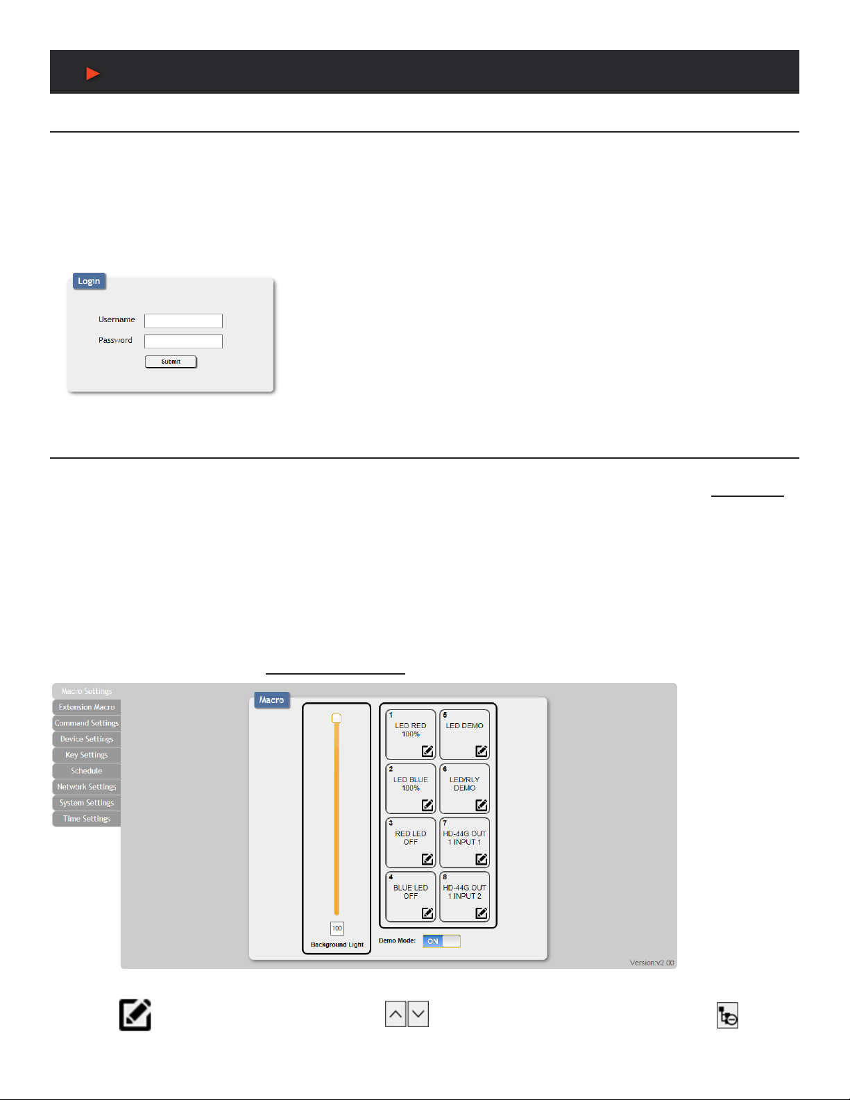
WEBGUI CONTROL ..............................................................7
MACRO SETTINGS ..............................................................7
EXTENSION MACRO ..........................................................9
COMMAND SETTINGS ........................................................10
DEVICE SETTINGS .............................................................10
KEY SETTINGS ....................................................................11
SCHEDULE .........................................................................12
NETWORK SETTINGS ........................................................13
SYSTEM SETTINGS ...........................................................14
TIME SETTINGS ..................................................................14
CONNECTION DIAGRAM ..........................................................15
INTRODUCTION
The ANI-8WP Wall-Plate Control System is a fantastic and useful
design for system installers and smart home users. With (8) direct
macro command buttons, plus an additional (8) macro commands
in the WebGUI, this unit has up to (16) commands that can be
executed with one push of a button for a total of 128 command
capacity inside this box. Soft and colorful LED design makes for
a professional presentation and the PoE (Power over Ethernet)
function allows for a exible installation without the need for an
external power supply. Further, this units relay output and scheduling
functions can be used to raise and lower projection screens, control
matrix switchers or any device that supports Telnet. This product
has a 3 year warranty.
PACKAGE CONTENTS
Before attempting to use this unit, please check the packaging and
make sure the following items are contained in the shipping carton:
• ANI-8WP Wall Plate Control System
• USB Type A to Mini USB OTG Connector
• (2) 3.5mm Terminal Block Pitch
• Decora Plate (white)
• 5 V/2.6A Power Adaptor
• Button Stickers (56 pcs)
• Users Guide
SYSTEM REQUIREMENTS
Active internet connection from Hub or Router and output to DC
controllable device.
SAFETY PRECAUTIONS
Please read all instructions before attempting to unpack, install or
operate this equipment and before connecting the power supply.
Please keep the following in mind as you unpack and install this
equipment:
• Always follow basic safety precautions to reduce the risk of re,
electrical shock and injury to persons.
• To prevent re or shock hazard, do not expose the unit to rain,
moisture or install this product near water.
• Never spill liquid of any kind on or into this product.
• Never push an object of any kind into this product through any
openings or empty slots in the unit, as you may damage parts
inside the unit.
• Do not attach the power supply cabling to building surfaces.
• Use only the supplied power supply unit (PSU). Do not use the
PSU if it is damaged.
• Do not allow anything to rest on the power cabling or allow any
weight to be placed upon it or any person walk on it.
• To protect the unit from overheating, do not block any vents or
openings in the unit housing that provide ventilation and allow for
sufcient space for air to circulate around the unit.
DISCLAIMERS
The information in this manual has been carefully checked and
is believed to be accurate. We assume no responsibility for any
infringements of patents or other rights of third parties which may
result from its use.
We assume no responsibility for any inaccuracies that may be
contained in this document. We make no commitment to update or
to keep current the information contained in this document.
We reserve the right to make improvements to this document and/
or product at any time and without notice.
COPYRIGHT NOTICE
No part of this document may be reproduced, transmitted,
transcribed, stored in a retrieval system, or any of its part translated
into any language or computer le, in any form or by any means
— electronic, mechanical, magnetic, optical, chemical, manual, or
otherwise — without the express written permission and consent.
© Copyright 2016. All Rights Reserved.
Version 1.6 AUG 2016
TRADEMARK ACKNOWLEDGMENTS
All products or service names mentioned in this document may be
trademarks of the companies with which they are associated.

2
FEATURES & SPECIFICATIONS
FEATURES
• (8) Macro buttons + (8) extra Macro programmable commands via WebGUI for up to 128 commands
• (1) Relay Output for additional device control
• Scheduling control for date/time specic events
• Supports Key Pad, Telnet and WebGUI control
• PoE or external DC power supply
• US (1) Gang wall plate design with adjustable LED intensity
• (56) Button Labels included (28 Pre-Printed & 28 Blank)
Specifications
• Input Ports: (8) Buttons
• Output Ports: (1) Relay (Terminal Block)
24V 10A, 100mOhms@1A 6VDC
(1) IP Control (RJ- 45)
• Power Supply: 5V/2.6A DC (US/EU standards, CE/FCC/UL certied)
• ESD Protection: Human Body Model:
±8kV (air-gap discharge)
±4kV (contact discharge)
• Dimensions (WxDxH): 1.8 x 1.5 x 4 in (46x35.5x103.5mm) / Jack Excluded
• Weight: 0.2 lb (Unit only) / 1.1 lb (Net)
• Chassis Material: Metal
• Color: White
• Operating Temperature: 32˚F~104˚F (0˚C~40˚C)
• Storage Temperature: −4˚F~140˚F (−20˚C~60˚C)
• Relative Humidity: 20~90% RH (non-condensing)
• Power Consumption: 3.3W
As product improvements are continuous, specications are subject to change without notice.
ANEUVIDEO

3
FRONT / Rear & SIDE PANEL
FRONT PANEL
q1~8 MACRO BUTTONS:Each buttons has (2) colors of LEDs with adjustable brightness
(0~100%) and can accommodate up to (16) commands.
28 Preprinted Button Labels Included
Rear / SIDE Panel
qRELAY OUT: Connect with a device that supports DC
0~24V/8A power or signal that supports a relay function.
wCONTROL: Connect from a PC/Laptop with active internet
service, Telnet or WebGUI control via a RJ-45 terminated cable.
This slot supports the PoE PD 48V function, which means when
the connected server/Hub supports PoE 48V, it can be powered
without the included DC supply.
eDC 5V: Plug the 5V DC power adaptor included in the package
and connect to an AC wall outlet for power supply.
rFIRMWARE UPDATE PORT: Procedure covered in a
separate document
ANEUVIDEO
q
q w e r
Table of contents