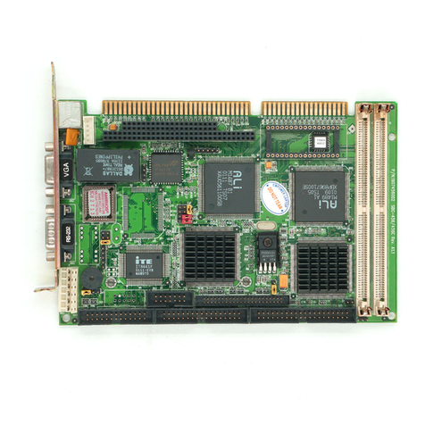
Aaeon SBC-411 User manual

SBC-411/411E
Half-size 486 All-in-One CPU Card
with Cache
StockCheck.com

FCC STATEMENT
THISDEVICECOMPLIESWITHPART15FCCRULES.OPERA-
TIONISSUBJECTTOTHEFOLLOWINGTWOCONDITIONS:
(1)THISDEVICEMAYNOTCAUSEHARMFULINTERFER-
ENCE.(2)THISDEVICEMUSTACCEPTANYINTERFERENCE
RECEIVEDINCLUDINGINTERFERENCETHATMAYCAUSE
UNDESIREDOPERATION.
THIS EQUIPMENT HAS BEEN TESTED AND FOUND TO
COMPLY WITH THE LIMITS FOR A CLASS"A" DIGITAL
DEVICE, PURSUANT TO PART 15 OF THE FCC RULES.
THESE LIMITS ARE DESIGNED TO PROVIDE REASON-
ABLE PROTECTION AGAINTST HARMFUL INTERFER-
ENCEWHEN THE EQUIPMENT IS OPERATED IN A
COMMERCIAL ENVIRONMENT. THIS EQUIPMENT GENER-
ATES,USES, AND CAN RADIATE RADIO FREQENCY
ENERGYAND, IFNOT INSTATLLEDANDUSED IN ACCOR-
DANCEWITH THE INSTRUCTION MANUAL, MAY CAUSE
HARMFUL INTERFERENCE TO RADIO COMMUNICA-
TIONS.OPERATION OF THIS EQUIPMENT IN A RESIDEN-
TIALAREA IS LIKELY TO CAUSE HARMFUL INTERFER-
ENCE IN WHICH CASE THE USER WILL BE REQUIRED
TOCORRECT THE INTERFERENCE AT HIS OWN EX-
PENSE.
StockCheck.com

Copyright Notice
This document is copyrighted, 1998, by AAEON Technology Inc.
All rights are reserved. AAEON Technology Inc. reserves the right
to make improvements to the products described in this manual at
any time without notice.
No part of this manual may be reproduced, copied, translated, or
transmitted in any form or by any means without the prior written
permission of AAEON Technology Inc. Information provided in
this manual is intended to be accurate and reliable. However,
AAEON Technology Inc. assumes no responsibility for its use, nor
for any infringements upon the rights of third parties which may
result from its use.
Acknowledgements
ALI is a trademark of Acer Laboratories, Inc.
AMD is a trademark of Advanced Micro Devices, Inc.
AMI is a trademark of American Megatrends, Inc.
AutoCAD and AutoShade are trademarks of Autodesk, Inc.
CHIPS Logotype is a registered trademark; Chips 65550 is a
trademark of Chip and Technologies, Inc.
IBM, PC/AT, PS/2 and VGA are trademarks of International
Business Machines Corporation.
Lotus, 1-2-3, and Symphony are trademarks of Lotus Development
Corp.
Microsoft Windows®and MS-DOS, are registered trademarks of
Microsoft Corp.
SMC is a trademark of Standard Microsystems Corporation.
TurboDLD Classic is a trademark of Panacea Inc.
UMC is a trademark of United Microelectronics Corporation.
WordPerfect is a trademark of WordPerfect Corporation.
VESA®is a registered trademark of Video Electronics Standards
Association.
All other product names or trademarks are properties of their
respective owners.
PartNo. 2007411001 SBC-411/411E A1 2nd Edition
Printed in Taiwan APRIL 1998
Written By : Steven Lin
StockCheck.com

Packing list
Before you begin installing your card, please make sure that the
following materials have been shipped:
• 1 SBC-411/411ECPUcard
• 1 user manual (this book)
• 1 6-pin to 5-pin adapter for keyboard
• 1 3½" Hard disk drive (IDE) interface cable (40 pin)
• 1 Floppy disk drive interface cable (34 pin)
• 1 Parallel port adapter (26 pin) and COM port (10-9 Pin) adapter
kit
• 1 Serial port adapter (10 to 9 pin)
• PC/104 Module mounting supports
• 1Ethernet 8029Utility Driver Disk(for SBC-411Eonly)
• 1 bag of screws and miscellaneous parts
If any of these items are missing or damaged, contact your distribu-
tor or sales representative immediately.
Notice
DearCustomer,
Thank you for purchasing the SBC-411/411E board. The user
manual is designed to help you get the most out of the SBC-411/
411E,please read it thoroughly before you install and use the board.
The product that you have purchased comes with a one-year
warranty, but AAEON cannot be responsible for misuse of the
product. Therefore, we strongly urge that the first read the manual
before using the product.
To receive the lastest version of the user manual, please visit our
Web site at: Taiwan: www.aaeon.com.tw
U.S.A : www.aaeon.com
StockCheck.com

Contents
Chapter 1: General Information ................................... 1
Introduction ........................................................................... 2
Features.................................................................................. 3
Specifications ......................................................................... 4
Board layout........................................................................... 6
Card dimensions.................................................................... 7
Chapter 2: Installation .................................................. 9
Jumpers and connectors .................................................... 10
Locating jumpers and connectors .................................... 11
Setting jumpers ................................................................... 12
Safety precautions ..........................................................13
Installing DRAM (SIMMs) ............................................... 14
InstallingSIMMs .....................................................................14
Removing SIMMs ...................................................................14
IDE hard drive connector (CN1) ...................................... 15
Floppy drive connector (CN2) .......................................... 17
Connecting the floppy drive.....................................................17
Parallel port connector (CN3) ........................................... 18
Installing the retaining bracket.................................................18
Power connector (CN4)...................................................... 19
RS-232 connectors (CN5, CN6) ....................................... 19
PCI Ethernet connector (CN7)......................................... 20
Keybaord connectors (CN10, CN11)............................... 20
Power LED connector (J1)................................................ 21
IDE LED connector (J2).................................................... 21
Int/Ext Buzzer (J3) ............................................................. 21
Ethernet link/active signal LED (J4)(J5)........................ 22
Power LED and keylock (J6) ............................................ 22
CPU fan power connector (+5V)(J9)................................ 23
Reset switch (JP1).............................................................. 23
StockCheck.com

DOC address setting (JP2) ............................................... 24
Clear CMOS (JP3) ............................................................. 24
DsikOnChip socket (U10)................................................. 25
Chapter 3 : AMIBIOS Setup .......................................... 27
General information ............................................................ 28
Starting AMIBIOS setup ........................................................28
AMIBIOS main menu.............................................................28
Using a mouse with AMIBIOS setup .....................................29
Using the keyboard with AMIBIOS setup..............................29
Standard Setup..................................................................... 30
Advanced Setup................................................................... 32
Chipset Setup ...................................................................... 38
Power Management Setup................................................. 41
PCI/PnP Setup ..................................................................... 43
Peripheral Setup.................................................................. 47
Security ................................................................................. 49
Utility..................................................................................... 53
Default................................................................................... 54
Exiting AMIBIOS............................................................... 55
Chapter 4 : Flat Panel/CRT Controller Display Drivers
and Utilities ........................................................... 57
Ethernet software configuration ....................................... 58
Appendix A : Watchdog Timer Demo Program .......... 59
Programming the watchdog timer .................................... 60
Appendix B : Installing PC/104 Modules ...................... 61
Installing PC/104 modules................................................. 62
StockCheck.com

Chapter 1 General Information 1
1
General
Information
This chapter gives background informa-
tionon theSBC-411/411E.
Sections include:
• Card specifications
• Board layout
CHAPTER
StockCheck.com

2SBC-411/411E User Manual
Introduction
TheSBC-411/411Eis an all-in-one single board 486 computer with an on-
boardPCIEthernetinterface(SBC-411E). Itpacks all the functions of an
industrial computer and its display capabilities into a single, half-size card.
This means the SBC-411/411E is your absolute best solution for embedded
applications.
The onboard Ethernet Realtek RTL 8029AS PCI bus Ethernet controller
supports remote boot ROM functions (SBC-411E only).
TheSBC-411/411EsupportstheM-Systems DiskOnChip 2000 (optional)
which is a new generation of high performance single-chip Flash Disk. It
provides a Flash Disk (as a BIOS expansion) which doesn't require any
bus, slots, or connectors. It is also the optimal solution for Single Board
Computers because of its small size, easy integration, plug-and-play
functionality, and its low power consumption. The DiskOnChip is
available in capacities from 2MB to 72MB and fits in a standard 32-pin DIP
socket.
Another feature of the SBC-411/411E is the inclusion of a high speed, local
bus IDE controller. This controller supports (through ATA PIO) mode 3
and mode 4 hard disks, enabling data transfer rates in excess of 11 MB/
second. Up to four IDE devices can be connected, including large hard
disks, CD-ROM drives, tape backup drives, or other IDE devices. The
built-in, enhanced IDE controller provides a 4-layer, 32-bit, posted write
buffer and a 4-layer, 32-bit read-prefetch buffer to boost IDE performance.
Onboard features include two high speed RS-232 serial ports, one bidirec-
tional SPP/EPP/ECP parallel port and a floppy drive controller. In addition
to the 486's 16 KB of on-chip cache memory, the SBC-411/411E includes an
extra128 KB of L2 onboard cache memory.
If program execution is halted by a program bug or EMI, the board's
watchdog timer can automatically reset the CPU or generate an interrupt.
This ensures reliability in unmanned or standalone systems.
StockCheck.com

Chapter 1 General Information 3
All configuration display and Ethernet (SBC-411E) is done through
software. A single Flash chip holds the system BIOS, VGA BIOS. This
minimizes the number of chip and eases configuration. You can
change the display BIOS or install a boot ROM simply by program-
ming the Flash chip.
TheSBC-411/411E supports5V EDODRAM.It also providesone 72-
pin SIMM (Single In-line Memory Module) sockets for its onboard
system DRAM. These sockets give you the flexibility to configure
your system from 4 MB to 32 MB of DRAM using the most economi-
cal combination of SIMMs.
Features
•CPU:AMDDX5-133 CPU(SQFP Type)
•Half-size:ISAbus CPU card
•BIOS:AMI FlashBIOS
•Chipset:ALi M1489/M1487
•Level2cache: Onboard 128KB L2 cache
•DiskOnChip: One 32-pin DIP socket supports the M-Systems'
DiskOnChip2000 Series, memory capacity from 2MB to72MB
•EthernetInterface(SBC-411E): Supports 10Base-T, remote boot ROM
function
StockCheck.com

4SBC-411/411E User Manual
Specifications
CPU: AMDDX5-133,(SQFPType)
BusInterface: ISA bus
BIOS: AMIFlashBIOS
Chipset: ALi1489/1487
Systemmemory: 4MB to 32MB. One 72-pin SIMM socket onboard supports
BEDO,EDO, Fast PageDRAM
L2cahcememoryF.D.D. : Onbaord 128KB L2 cache memory.Supports up to
twofloppy disk drives, 5.25" (360KBand1.2MB) and/or 3.5" (720KB, 1.44MB,
and2.88MB)
EnhancedIDE: Supports two hard disk drive. Supports PIO mode 3/4
Multi-modeparallel port: Configured toLPT1,LPT2, LPT3 ordisabled.
Supports SPP, ECP, and EPP modes
Serialport: Two RS-232 ports. Ports can be individually configured from
COM1 to COM4 or disabled.
Keyboardconnector: 6-pin mini-DIN connectorsupportsstandardPC/AT
keyboard
Ethernetcontroller(SBC-411E): RealtekRTL8029AS10-BasePCI-Bus
Ethernet controller
EtherentInterface: Software drivers available. Supports remote boot ROM
function
SSD interface: One 32-pin DIP socket supports the M-Systems DiskOnChip
2000series, memory capacity from 2MBto72MB
PC/104connector: 104-pin connector for a 16-bit bus
Watchdog Timer: Can generate a system reset or IRQ15. The time interval is
software selectable (2sec~128min, 1sec/step)
DMAchannels: 7
Interruptlevels: 15
Powermanagement: I/O Peripheral devices support power saving and doze/
standby/suspend modes
StockCheck.com

Chapter 1 General Information 5
Powersupplyvoltage: +5V(4.75Vto5.25V)
+12V(11.4V to 12.6V)
Max.powerrequirement: +5V @ 3A
Operatingtemperature: 32 to140°F(0to60°C)
Boardsize: 7.3"(L) x 4.8"(W)(185mmx122mm)
Weight: 0.23kg
StockCheck.com

6SBC-411/411E User Manual
Board layout
Socket for
DiskOnChip
M48T86PCI
ALI
M1487 B1
RTL8019A
ALI
M1489
Am486 DX4-133
RTL8029AS
PC-104
connector
AMIFlash
BIOS
AMD486
DX5-133CPU
Upto 32MB
DRAM
Power
connector
Parallel port
connector
COM2
COM1
FDD
interface
ALi
Chipset
IDE
connector
ALi
Chipset
PCI10Base-T
Keyboard
StockCheck.com

Chapter 1 General Information 7
Card dimensions
185.00
178.00
21.7
80.51
5.11
122.00
98.50 19.50
3.0
72.6 27.0
4.0
98.50 27.1
4.1
4.0
StockCheck.com

8SBC-411/411E User Manual
StockCheck.com

Chapter 2 Installation 9
2
Installation
This chapter describes how to set up the
SBC-411/411Ehardware,including
instructions on setting jumpers and
connecting peripherals, switches, and
indicators. Be sure to read all safety
precautions before you begin the installa-
tion procedure.
CHAPTER
StockCheck.com

10 SBC-411/411E UserManual
Jumpers and connectors
Connectors on the board link it to external devices such as hard
disk drives, a keyboard, or floppy drives. In addition, the board has
a number of jumpers that allow you to configure your system to
suit your applications.
The table below lists the function of each of the board jumpers and
connectors.
Jumpers and connectors
Label Function
CN1 IDE hard drive connector
CN2 Floppy drive connector
CN3 Parallel port connector
CN4 Power connector
CN5 COM1 connector
CN6 COM2 connector
CN7 Ethernet connector
CN8 (optional) ISA 10Base-T
CN9 (optional) DC_JACK connector
CN10 Internal keyboard connector
CN11 Keyboard connector
J1 Power LED connector
J2 IDE LED connector
J3 Int/Ext buzzer
J4 Ethernet link signal LED
J5 Ethernet active signal LED
J6 Power LED & KB_LOCK
J7 (optional) LED_LINK ISA 10Base-T
J8 (optional) LED_RX ISA 10Base-T
J9 CPU fan power connector
JP1 Reset switch
JP2 DOC address setting
JP3 Clear CMOS
StockCheck.com

Chapter 2 Installation 11
M48T86PCI
ALI
M1487 B1
RTL8019A
ALI
M1489
Am486 DX4-133
RTL8029AS
ParallelPort
Connector (CN3)
COM 1
(CN5)
Locating jumpers and connectors
JP1
J3
FDD
Connector
(CN2)
COM 2
(CN6)
IDE
connector
(CN1)
J1
U10
JP2
AMI Flash
BIOS
JP3
J6
PC/104
connector
CN10
internal
keyboard
Power
connector
(SBC-411E only)
PCI 10-BaseT
RJ-45 Jack
(CN7)
(optional)ISA10-BaseT
RJ-45 Jack (CN8) KB
connector
(CN11)
J5
J4
J7 J8
J2 Upto 32MB
DRAM
J9
StockCheck.com

12 SBC-411/411E UserManual
Setting jumpers
You configure your card to match the needs of your application by
setting jumpers. A jumper is the simplest kind of electric switch. It
consists of two metal pins and a small metal clip (often protected
by a plastic cover) that slides over the pins to connect them. To
"close" a jumper you connect the pins with the clip. To "open" a
jumper you remove the clip. Sometimes a jumper will have three
pins, labeled 1, 2, and 3. In this case you would connect either pins
1 and 2 or 2 and 3.
The jumper settings are schematically depicted in this manual as
follows:
A pair of needle-nose pliers may be helpful when working with
jumpers.
If you have any doubts about the best hardware configuration for
your application, contact your local distributor or sales representa-
tive before you make any changes.
Generally, you simply need a standard cable to make most connec-
tions.
13
2
Open Closed Closed 2-3
1 2 3
StockCheck.com

Chapter 2 Installation 13
Safety Precautions
Warning! Alwayscompletelydisconnect the power cord from
yourchassiswhenever you are working onit.Do
not make connections while the power is on,
sensitiveelectroniccomponentscanbedamaged
bythesudden rush of power. Onlyexperienced
electronicspersonnelshouldopenthePCchas-
sis.
Caution! Alwaysgroundyourself to remove any static
chargebeforetouching the CPU card. Modern
electronic devices are very sensitive to static
electric charges. Use a grounding wrist strap at all
times. Place all electronic components on a
static-dissipative surface or in a static-shielded
bag when they are not in the chassis.
StockCheck.com

14 SBC-411/411E UserManual
Installing DRAM (SIMMs)
TheSBC-411/411E CPU card provides one 72-pin SIMM(Single In-
line Memory Module) socket and supports between 4 MB to 32
MBofRAM.
Installing SIMM
Note: that the modules can only fit into a socket one way.
1. Insert the memory module into the socket at a moderate angle.
2. Push the module toward the vertical posts at both ends of the
socket until the module is upright, and the retaining clips at
both ends of the module click into place. When positioned
correctly, the pins on top of the vertical posts should corre-
spond to the circular holes on the ends of the module.
Removing SIMM
If you need to remove a SIMM, follow the procedures below:
1. Supporting the SIMM with a finger, use a pen or a similarly
shaped object and press one retaining clip straight down.
2. Repeat for the other side. When released, the retaining clips will
push the SIMM up and out of its upright position.
3. Carefully pull the SIMM out of the socket with your fingers.
StockCheck.com
This manual suits for next models
1
Table of contents
Other Aaeon Computer Hardware manuals

Aaeon
Aaeon PCM-8300 User manual

Aaeon
Aaeon NanoCOM-WHU User manual

Aaeon
Aaeon AEC-6643 User manual

Aaeon
Aaeon EPIC-HD07 User manual

Aaeon
Aaeon UPN-EHLCB User manual
Aaeon
Aaeon SBC-356 User manual

Aaeon
Aaeon GENE-APL6 User manual

Aaeon
Aaeon PFM-336I User manual

Aaeon
Aaeon PCM-4330 User manual

Aaeon
Aaeon UP Squared 6000 User manual

Aaeon
Aaeon AQ7-LN User manual

Aaeon
Aaeon RICO-3288 User manual

Aaeon
Aaeon ETX-821 User manual

Aaeon
Aaeon COM-ICDB7 User manual

Aaeon
Aaeon ETX-700 User manual

Aaeon
Aaeon PCM-6892 Rev.B User manual

Aaeon
Aaeon SBC-350A User manual

Aaeon
Aaeon PCM-5335 User manual

Aaeon
Aaeon EMB-A50M User manual

Aaeon
Aaeon EPIC-BT07-A13 User manual