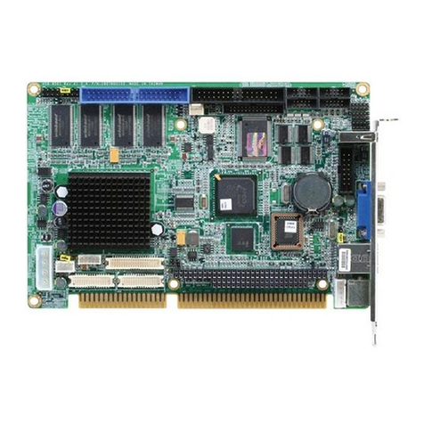
Aaeon SBC-598 User manual

SBC-598
Full-Size PCI/ISA Pentium CPU Card

FCC STATEMENT
THISDEVICECOMPLIESWITHPART15FCCRULES.OPERA-
TIONISSUBJECTTOTHEFOLLOWINGTWOCONDITIONS:
(1)THISDEVICEMAYNOTCAUSEHARMFULINTERFER-
ENCE.(2)THISDEVICEMUSTACCEPTANYINTERFERENCE
RECEIVEDINCLUDINGINTERFERENCETHATMAYCAUSE
UNDESIREDOPERATION.
THIS EQUIPMENT HAS BEEN TESTED AND FOUND TO
COMPLY WITH THE LIMITS FOR A CLASS "A" DIGITAL
DEVICE, PURSUANT TO PART 15 OF THE FCC RULES.
THESE LIMITS ARE DESIGNED TO PROVIDE REASON-
ABLE PROTECTION AGAINTST HARMFUL INTERFER-
ENCE WHEN THE EQUIPMENT IS OPERATED IN A
COMMERCIAL ENVIRONMENT. THIS EQUIPMENT
GENERATES,USES, AND CAN RADIATE RADIO
FREQENCY ENERGYAND, IFNOTINSTATLLEDANDUSED
IN ACCORDANCEWITH THE INSTRUCTION MANUAL,
MAY CAUSEHARMFUL INTERFERENCE TO RADIO
COMMUNICATIONS. OPERATION OF THIS EQUIPMENT
IN A RESIDENTIALAREA IS LIKELY TO CAUSE HARM-
FUL INTERFERENCE IN WHICH CASE THE USER WILL
BE REQUIRED TOCORRECT THE INTERFERENCE AT HIS
OWN EXPENSE.

Copyright Notice
This document is copyrighted, 1998, by AAEON Technology Inc.
All rights are reserved. AAEON Technology Inc. reserves the
right to make improvements to the products described in this
manual at any time without notice.
No part of this manual may be reproduced, copied, translated or
transmitted in any form or by any means without the prior written
permission of AAEON Technology Inc. Information provided in
this manual is intended to be accurate and reliable. However,
AAEON Technology Inc. assumes no responsibility for its use,
nor for any infringements upon the rights of third parties which
may result from its use.
Acknowledgements
AMD is a trademark of Advanced Micro Devices, Inc.
Award BIOS is a trademark of Award Software International, Inc.
AutoCAD and AutoShade are trademarks of Autodesk, Inc.
CHIPS Logotype is a registered trademark. Chips 65554 is a
trademark of Chip and Technologies, Inc.
Cyrixisatrademark of Cyrix Corporation.
IBM, PC/AT, PS/2, and VGA are trademarks of International
Business Machines Corporation.
Intel and Pentium are trademarks of Intel Corporation.
Lotus 1-2-3, and Symphony are trademarks of Lotus Development
Corp.
Microsoft Windows® and MS-DOS, are registered trademarks of
Microsoft Corp.
SiS is a trademark of Silicon Integrated System Corp.
SMC is a trademark of Standard Microsystems Corporation.
UMC is a trademark of United Microelectronics Corporation.
VESA®is a registered trademark of Video Electronics Standards
Association.
All other product names or trademarks are properties of their
respective owners.
PartNo. 2007598000 SBC-5981st Edition
Printed in Taiwan March 1998

Packing list
Before you begin installing your card, please make sure that the
following materials have been shipped:
• 1 SBC-598 CPU Card
• 1 6-pin mini-DIN dual outlet adapter for keyboard and PS/2
mouse
• 1 Hard disk drive (IDE) interface cable (40 pin)
• 1 Floppy disk drive interface cable (34 pin)
• 1 Parallel port adapter (26 pin) and COM2 adapter (9 pin) kit
• 4 Utility disks with SiS 5598 utility programs and drivers
If any of these items are missing or damaged, contact your
distributor or sales representative immediately.

Contents
Chapter 1: General Information ....................... 1
Introduction ........................................................................... 2
Features.................................................................................. 3
Specifications ......................................................................... 3
Board layout........................................................................... 5
Card dimensions.................................................................... 6
Chapter 2: Installation ....................................... 7
Safety precautions ................................................................. 8
SOCKETS .............................................................................. 8
CPUInstallation/Removal ........................................................ 8
SIMMInstallation/Removal ....................................................10
DIMMInstallation/Removal....................................................11
DiskOnChip Socket (U16) ......................................................12
Jumpers and Connectors................................................... 14
Setting jumpers ................................................................... 16
Clear CMOS Data (JP1) ........................................................17
Onboard SVGA Setting (JP2).................................................17
SIMM Voltage (JP3) ...............................................................17
PCI Bus Clock Sync/Async Settings (JP4) ............................18
CPU External Clock Selection (JP5) ......................................18
CPU Clock Ratio (JP6)...........................................................19
Vcore Voltage Selection (JP7) ................................................20
CPU Type Selection (JP8) ......................................................21
Hardware Reset (JP9) ............................................................21
Buzzer Setting (JP10)..............................................................21
DOC Address (JP11) ..............................................................22
Memory Bank Selection (M1).................................................23
CPU Jumper Setting Example.................................................24
Connector Descriptions ..................................................... 26
USB Connector (CN1) ...........................................................26

Hard Disk LED Connector (CN2)..........................................26
Thermal Alarm LED (CN3)....................................................27
Power LED & Keylock Connector (CN4) .............................27
Fan Connector (CN5) .............................................................27
Primary and Secondary IDE HD connector (CN6, CN7) ......28
Digtial I/O Port connector (CN8) ...........................................29
Reserved Connector (CN9) ....................................................29
Reserved IR connector (CN10)..............................................29
Floppy Drive Connector (CN11) .............................................30
Parallel Port Connector (CN12)..............................................31
COM2 Connector (CN13) ......................................................31
Power Connector (CN14).......................................................32
COM1 Connector (CN15) ......................................................32
CRT Connector (CN16) ..........................................................32
KB Connector and Keyboard/PS2 Mouse Connector (CN17,
CN18)......................................................................................33
Chapter 3: Award BIOS Setup .......................... 35
System test and initialization ............................................. 36
Systemconfiguration verification ............................................36
AWARD BIOS setup........................................................... 37
Entering setup..........................................................................38
Standard CMOS setup ............................................................38
BIOS features setup................................................................39
Virus Warning..........................................................................39
CHIPSET features setup ........................................................42
Power management setup.......................................................45
PnP/PCI Configuration setup ..................................................50
Load BIOS Defaults / Load Setup Defaults ...........................52
Integrated Peripherals Setup ...................................................53
Supervisor/User Password Setting..........................................56
IDE HDD Auto Detection ......................................................58
HDD Low Level Format Utility..............................................59
SAVE & Exit Setup.................................................................60
ExitWithout Saving .................................................................60
Chapter 4: SiS 5598 VGA Drivers ...................... 61
System Requirements ........................................................ 62
Windows 95 .......................................................................... 62
Windows 95 (Display Driver Installation) ...............................62
Selecting resolution, color depth, and refresh ..........................63
Windows 3.3.
3.3.
3. x ........................................................................ 64
Installating ...............................................................................64
Graphics Setup ........................................................................64
Power Saving Setup in Windows 3.x ......................................65
NT 3.5X................................................................................. 65
Selecting resolution and color depth ........................................66
NT 4.0 ................................................................................... 66
Selecting resolution and color depth ........................................67
DOS ....................................................................................... 68
VGAUtility .............................................................................68
Video Mode Setting .................................................................68
Frame Rate Setting .................................................................68
Power Saving Setting ..............................................................68
Appendix A: Programming the Watchdog
Timer ............................................. 69
Programming the Watchdog Timer .................................. 70


Chapter 1 General Information 1
1
General
Information
This chapter provides background
informationfor the SBC-598.
Sections include:
• Card specifications
• Board layout
CHAPTER

2SBC-598 User Manual
Introduction
TheSBC-598 is an all-in-oneSingle Board Computer (SBC) capable
ofhandling the Intel Pentium P54C, P55C (MMX),AMDK6, as well
asthe Cyrix 6x86(M1)and6x86MX(M2) CPUs. Reliability,
performance, flexibility, and adequate expansion capabilities are
essential qualities for SBCs and their embedded applications and
the SBC-598 provides all of these.
If program execution is halted by a program bug or EMI, the board's
watchdog timer can automatically reset the CPU or generate an
interrupt. This ensures reliability in unmanned or standalone
systems.
Our Smart Temperature Control technology (LM75 chip) monitors
the CPU temperature and automatically slows down the CPU
frequency when the CPU temperature exceeds a specified safe
range, helping your system recover from abnormal temperature
fluctuations.
TheSBC-598 supports the M-Systems DiskOnChip 2000 family of
flash disk products which are small, plug-and-play, solid-state disks
in a standard 32-pin DIP package with capacities ranging from 2MB
to 72MB. This is often a far superior solution to a standard hard
drive as the flash disk has no mechanical parts, increasing overall
systemreliability.
Four synchronous two-way High Drive chips allows you to add
more peripheral cards and expand functionality in a reliable manner.
Four 72-pin SIMM sockets as well as one 168-pin DIMM socket
gives you the flexibility of having from 2MB to 256MB of DRAM
and up to 128MB of SDRAM.
Other features include 2 high speed RS-232 serial ports with 16C550
UARTs, 1 bidirectional SPP/EPP/ECP parallel port and the support
for 2 floppy drives. In addition, the SBC-598 has a 512KB pipeline-
burst L2 cache for increased performance.
The SBC-598 also includes a high speed, local bus IDE controller
which supports (through ATA PIO) mode 3 and mode 4 hard disks,
Ultra DMA/33 (data transfer rates up to 33MB/sec) and up to 2 IDE
devices.

Chapter 1 General Information 3
Features
•SupportsIntelPentiumP54C/P55C (MMX) 166~233MHz, AMD K6, and
CyrixM1/M2CPUs
•Full-sizePCI/ISA Bus Card, PICMG2.0 standard
•High Drive supports more peripheral cards
•SiS5598 Chipset: XGA controller integrated
•SupportsUltraDMA/33 for EIDE interface
•DiskOnChip: One 32-pin DIP socket supports the M-Systems DiskOn-
Chip2000 series, memory capacity from2MB to 72MB.
•Smart Temperature Control: LM75supports CPU temperature monitor
ing.
Specifications
CPU: IntelPentiumP54C,P55C(MMX)166~233MHz,Cyrix6X86(M1)
PR100+~166+,6x86MX(M2)PR166~266MHz,AMDK6PR2166~233
Businterface: PCI/ISA bus, PICMG 2.0 standard
CPUSocket:Socket 7
BIOS:Award FLASH BIOS
Chipset:SiS 5598 meets PC97 requirements. Video/graphics accelerator
and PMU controller integrated.
SuperI/OChipset:ITEIT8661F
Level2 Cache: Onboard 512KB pipeline-burst L2 cache.
SmartTemperatureControl:LM75 supports CPU temperaturemonitor-
ing.
Systemmemory: 2MB up to 256MB. Four 72-pin SIMM sockets and one
168-pin DIMM socket onboard.
EnhancedIDEharddiskdrive(HDD)interface:Support up to four hard
disk drives. Supports PIO mode 1-4, PCI Bus Mastering, Multi-word
DMA, and Ultra DMA/33.
High Drive Chips: 4 synchronous two-way High Drive chips onboard.

4SBC-598 User Manual
Floppydisk drive(FDD) interface:Supports up to two floppy disk drives,
5.25"(360KB and 1.2MB)and/or3.5"(720KB,1.44MB, and 2.88MB).
Multi-modeparallelports:Configuredto LPT1, LPT2,LPT3,ordisabled.
Supports SPP, ECP, and EPP.
Serialports: 2 RS-232 serial ports. Ports can be individually configured
asCOM1,COM2, COM3, COM4, or disabled.
IrDAinterface: Infared wireless communication with compatible devices.
Keyboard/mouseconnector:6-pin mini DIN connector supports standard
PC/AT keyboard and PS/2 mouse.
USBconnectors: Dual USB connectors on board.
DMAchannels:7
Interruptlevels:15
Watchdog Timer: Can generate a system reset, IRQ15, or NMI, and
supports selectable timeout interval (2 sec~128 min, 1 sec/step).
VGAcontroller:SiS 5598, 64-bitgraphics engine integrated.
Powermanagement: I/O peripheral devices support power saving and
doze/standby/suspend modes. APM 1.2 compliant
Display memory: Supports shared system memory up to 4MB.
Displaytype: Supports CRTdisplay.
Resolution:Support up to 1024 x 768 @ 16.7M colors.
SSD interface: One 32-pin DIP socket supports the M-Systems DiskOn-
Chip2000 series, memory capacity from2MB to 72MB.
Powersupplyvoltage: +5V(4.75Vto5.25V)
PowerRequirement:
BareBoard: +5V@2A
PentiumMMX-200: +5V@6A
AMDK6-233: +5V@10A
Operatingtemperature:32°F to140°F(0°Cto60°C)
Boardsize:13.31"(L)x4.8"(W)(338mmx122mm)
Boardweight: 0.88lbs(0.4kg)

Chapter 1 General Information 5
Board layout
S783
W25P240AF-6
XILINX
XC9572
Socket 7
SBC-598 Pentium CPU CARD
Winbond
iTE
IT8661F
5598
SIS
Power Connector
FDD Interface
Parallel Port
COM2 RS-232
Primary IDE
DIMM Socket
COM1 RS-232 VGA Port
USB Connectors
Secondary IDE
Keyboard/
Mouse Port
DiskOnChip
Socket
High Drive Chips
Intel Socket 7
SiS 5598
Chipset/SVGA
4 SIMM Sockets

6SBC-598 User Manual
122
15.444
8.001
80.624
5.741
47.600
12.141
62.739
1.930
14.478
47.270
42.495
19.5
338.460
331.490
4.01
2.96
4.0
98.5
Card dimensions

Chapter 2 Installation 7
2
Installation
This chapter explains setup procedures
forthe SBC-598 hardware, including
instructions on setting jumpers and
connecting peripherals, switches and
indicators. Be sure to read all safety
precautions before you begin the installa-
tion procedure.
CHAPTER

8SBC-598 User Manual
Safety precautions
Warning! Alwayscompletely disconnectthepower cordfrom
yourchassis whenever youare working onit. Do
not make connections while the power is on
because sensitive electronic components can be
damagedbythe suddenrushof power. Only
experiencedelectronicspersonnelshouldopen
the PC chassis.
Caution! Alwaysground yourselftoremove anystatic
chargebefore touching theCPU card. Modern
electronic devices are very sensitive to static
electric charges. Use a grounding wrist strap at all
times. Place all electronic components on a
static-dissipative surface or in a static-shielded
bag when they are not in the chassis.
Conflicts! The VGA controller of SBC-598 uses IDSEL No.
31, which is the same as that of the first PCI slot
(i.e., "PCI1") on the PCI backplane (PICMG 2.0
standard). Therefore,when theonboard VGA
function is enabled, the first PCI slot on the PCI
backplanecannot haveaperipheral cardplugged
inotherwise hardwareconflictscan result.
SOCKETS
CPU Installation/Removal
The SBC-598 CPU card supports most Pentiums and Pentium-
compatible CPUs. The system's performance depends on the CPU
you choose. You can install or upgrade the CPU in the board's
Intel Socket 7 socket by following the procedures outlined below. If
your system has an existing CPU, you need to remove it before
installing the new CPU.

Chapter 2 Installation 9
Installing the CPU
To install the CPU, follow the instructions that came with it. If no
documentation was provided, the general procedures for installing
a CPU are outlined below:
1. Make sure the socket lever is up as far as it can go. The Pin 1
position is indicated by a notch on the corner of the socket.
2. Match Pin 1 on the CPU with the Pin 1 position on the socket.
3. Insert the CPU. If it does not go in easily, lift the lever higher.
4. Press the lever down. The sliding plate will move forward to
position the CPU. You will feel some resistance in the lever as
the CPU is secured into place. When the CPU is properly
installed, the lever will snap into place at the side of the socket.
When you install a new CPU, you may have to adjust other
settings on the board, such as CPU type, CPU clock, and PCI
speed, in order to accommodate it. Make sure that the settings are
correct for your CPU.
WARNING:Impropersettings maydamagethe CPU.
Removing the CPU
1. Disconnect power from the chassis, and unplug all connections
to the CPU card. Then, remove the CPU card from the chassis
by following the instructions in the user's manual for your
chassis.
2. Unlock the socket by gently lifting the metal bar and lift the
CPU out of the socket. You may find a chip puller helpful which
is available at an electronics hobbyist supply store.

10 SBC-598 User Manual
SIMM Installation/Removal
InstallingSIMMs
Note that the modules can only fit into a socket one way.
1. Insert the memory module into the socket at a moderate angle.
2. Push the module toward the vertical posts at both ends of the
socket until the module is upright and the retaining clips at both
ends of the module click into place. When positioned correctly,
the pins on top of the vertical posts should correspond to the
circular holes on the ends of the module.
3. Repeat steps 1 and 2 for each module you install.
Removing SIMMs
1. Supporting the SIMM with a finger, use a pen or a similarly
shaped object and press one retaining clip straight down.
2. Repeat for the other side. When released, the retaining clips will
push the SIMM up and out of its upright position.
3. Carefully pull the SIMM out of the socket with your fingers.
4. Repeat the above steps for each module you remove.

Chapter 2 Installation 11
DIMM Installation/Removal
The SBC-598 provides one 168-pin DIMM socket for an SDRAM
module. You can select an SDRAM module between 16MB to
64MB. However, please don't use both SIMMs and DIMMs
simultaneously.
Installing DIMMs
The DIMM installation procedure is slightly easier.
Note that the module can only fit into a socket one way.
1. Open the fastening clips on both sides of the socket.
2. Insert the DIMM into the socket. Make sure that the pins line
up properly.
3. Gently close the fastening clips until the DIMM is firmly seated.
Removing DIMMs
1. Open the fastening clips on both sides of the socket.
2. Remove the DIMM from the socket.

12 SBC-598 User Manual
DiskOnChip Socket (U16)
The M-Systems DiskOnChip 2000 (DOC-2000) family of
products provides a single chip solid-state flash disk in a standard
32-pin DIP package. The DOC-2000 is a small, plug-and-play,
solid-state disk with no moving parts, resulting in a significant
reduction in power consumption and an increase in reliability.
The DOC-2000 family of products is available in capacities
ranging from 2MB up to 72 MB, unformatted. This way, the same
socket on the target platform will not have to be changed. In order
to manage the disk, the DOC-2000 includes the TrueFFS, M-
Systems Flash File System proprietary software. The DOC-2000
package is pin-to-pin compatible with standard 32-pin EPROM
devices.
Figure1-MD2200 Pin-out
OE/
Note 1: Pins A13 through A16 are not used by
the MD2200. They are kept for socket backward
compatibilitywith ED1100(DiskOnChip 1000)
Note 2: Pins 1 and 30 are not used by the
MD2200
pin
Name Description Pin Number Direction Note
A0-A12 Address bus 4-12,23,25-27 Inputs
A13-A16 Address bus 2,3,28,29 Inputs 1
D0-D7 Data bus 13-15,17-21 I/O
CE/ Chip Enable 22 Input
OE/ Output Enable 24 Input
WE/ Write Enable 31 Input
NC Not connected 1.30 2
VCC Power 32
GND Ground 16
Refer to the instructions for configuring the DOC address (JP11)
later in this chapter.
Table of contents
Other Aaeon Computer Hardware manuals

Aaeon
Aaeon SBC-657B User manual

Aaeon
Aaeon FSB-860B User manual

Aaeon
Aaeon UPN-EHLCB User manual

Aaeon
Aaeon PCM-5335 User manual

Aaeon
Aaeon SBC-551 User manual

Aaeon
Aaeon HSB-800P User manual

Aaeon
Aaeon GENE-APL5 User manual

Aaeon
Aaeon EPIC-HD07 User manual

Aaeon
Aaeon NEZHA-N97 User manual

Aaeon
Aaeon PICO-BT01 User manual

Aaeon
Aaeon SBC-656 User manual

Aaeon
Aaeon BOXER-6639 User manual

Aaeon
Aaeon HSB-660S/I User manual

Aaeon
Aaeon UPS-EDGE-EHL01 User manual

Aaeon
Aaeon UPN-EDGE-EHL01 User manual

Aaeon
Aaeon RICO-3288 User manual

Aaeon
Aaeon PCM-6892 Rev.B User manual

Aaeon
Aaeon SBC-350A User manual

Aaeon
Aaeon FSB-866G User manual

Aaeon
Aaeon HSB-810A User manual