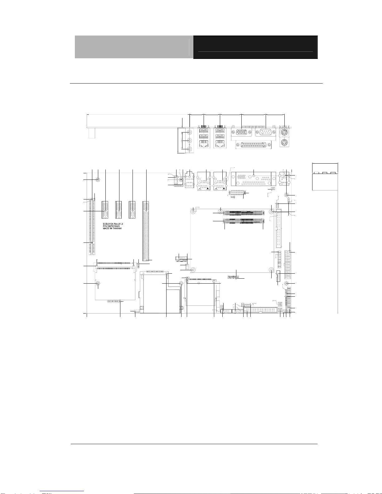
Aaeon ECB-915A User manual

COM Express
Carrier Board ECB-915A
Chapter1QuickInstallationGuide1-1
Quick
Installation
Chapter
1
Guide
Part No. 2007915A11 Printed in Taiwan Oct. 2007

COM Express ECB-915A
Carrier Board
Chapter 1 Quick Installation Guide 1-2
1.1 Safety Precaution
Always completely disconnect the power cord
from your board whenever you are working on
it. Do not make connections while the power is
on, because a sudden rush of power can
damage sensitive electronic components.
Always ground yourself to remove any static
charge before touching the board. Modern
electronic devices are very sensitive to static
electric charges. Use a grounding wrist strap at
all times. Place all electronic components on a
static-dissipative surface or in a static-shielded
bag when they are not in the chassis

COM Express ECB-915A
Carrier Board
Chapter 1 Quick Installation Guide 1-3
1.2 Location of Connectors and Jumpers
Component Side
EXPRESS CARD
PCIE1 PCIE2 PCIE3
PCI1
CN11
CN24
CN16
CN15
CN4CN5
JP6
MPCI1
CN17
JP9 FLOPPY
CN7 CN2
CN8
SW1 SW2
JP7
CN25 CN26
JP8
CN6
SATA3
CFD1
CN29
CN28
JP5
CN21
CN14
JP10
CN22
CN12 RJUSB1
CN27
JP2
CN9
JP4
JP1
CN10
IDE1
CN23
JP3
CN3

COM Express ECB-915A
Carrier Board
Chapter 1 Quick Installation Guide 1-4
1.3 Mechanical Drawing
Component Side
EXPRESS CARD
0.00
0.00
49.66
18.10
3.69
72.14
44.90
71.21
14.92
69.92
77.22
74.24
170.62
105.85
168.72
7.49
11.30
16.51
199.84
27.81
48.13
68.45
88.77
152.90
79.75 81.24
137.48
149.80
133.60
143.29
141.00
203.52
192.08
199.84
153.54
178.32
202.64
249.46
295.40
206.62
205.65
198.13
204.41
220.57
179.91
233.79
173.93
158.91
199.91
275.91
185.63
276.51
283.86
164.23
166.57
176.98
298.48
152.08
150.94
285.62
205.71
263.41
150.08
138.08
65.08
72.33
53.46
141.00
44.90
118.86
59.68
149.40
190.13
44.83
202.80 204.28
221.68
234.17
244.41
239.52
2.37 3.75
10.64 12.88
223.01
52.54
289.05
294.13
1.84
8.07
303.53
25.47
29.66
298.07
44.90
91.61
92.02
275.91
59.70
285.26 286.64
301.75
13.79
298.07
303.42
16.51
JP8
153.54 21.28 24.32 32.17 35.99 28.11
12.50 12.50 6.50
37.50
38.10
306.00
210.00
152.08

COM Express ECB-915A
Carrier Board
Chapter 1 Quick Installation Guide 1-5
1.4 List of Jumpers
The board has a number of jumpers that allow you to configure your
system to suit your application.
The table below shows the function of each of the board's jumpers:
Jumpers
Label Function
JP1 BIOS Selection
JP2 Clear CMOS Selection
JP3 Jumper for Testing & Debug
JP4 LVDS Voltage Selection
JP5 BIOS write protection Selection
JP6 COM1 Ring Voltage Selection
JP7 COM3 Ring Voltage Selection
JP8 COM4 Ring Voltage Selection
JP9 CPLD programming Jumper
JP10 CF Card Selection

COM Express ECB-915A
Carrier Board
Chapter 1 Quick Installation Guide 1-6
1.5 List of Connectors
The board has a number of connectors that allow you to configure
your system to suit your application. The table below shows the
function of each board's connectors:
Label Function
CN2 Front Panel
CN3 ATX Power Connector
CN4 COM-Express Connector (Row A & B)
CN5 COM-Express Connector (Row C & D)
CN6 Digital IO Connector
CN7 Floppy Connector
CN8 IR Connector
CN9 LVDS Connector
CN10 TV-Out Connector
CN11 CRT + COM1 + Printer port Connector
RJUSB1 LAN + USB Connector (Intel 82562ET)
CN12 LAN + USB Connector (Marvell 88E8053)
CN14 USB Connector
CN15 Audio 5.1 Channel Connector
CN16 CD-IN Connector
CN17 Express Card Connector
CN21 PCI-Express 16X Graphic Connector
CN22 CPU Fan Connector

COM Express ECB-915A
Carrier Board
Chapter 1 Quick Installation Guide 1-7
CN23 System Fan Connector
CN24 Audio Connector
CN25 COM3 Connector
CN26 COM4 Connector
CN27 Keyboard & Mouse Connector
CN28 LPC Connector
CN29 COM2 Connector
IDE1 IDE Connector
CFD1 Compact Flash Connector
SATA3 SATA Connector
PCIE1 PCI Express 1X Connector
PCI1 PCI Slot Connector
MPCI1 Mini PCI Connector
SW1 Reset Button
SW2 Power Button

COM Express ECB-915A
Carrier Board
Chapter 1 Quick Installation Guide 1-8
1.6 Setting Jumpers
You configure your card to match the needs of your application by
setting jumpers. A jumper is the simplest kind of electric switch. It
consists of two metal pins and a small metal clip (often protected by
a plastic cover) that slides over the pins to connect them. To “close”
a jumper you connect the pins with the clip.
To “open” a jumper you remove the clip. Sometimes a jumper will
have three pins, labeled 1, 2 and 3. In this case you would connect
either pins 1 and 2 or 2 and 3.
123
Open Closed Closed 2-3
A pair of needle-nose pliers may be helpful when working with
jumpers.
If you have any doubts about the best hardware configuration for
your application, contact your local distributor or sales
representative before you make any change.
Generally, you simply need a standard cable to make most
connections.

COM Express ECB-915A
Carrier Board
Chapter 1 Quick Installation Guide 1-9
1.7 BIOS Selection (JP1)
√From CPU Board From Carried Board
1 2 3 1 2 3
■●○
□●●
1.8 Clear CMOS Selection (JP2)
√Normal Clear CMOS
1 2 3 1 2 3
■●○
□●●
1.9Jumper for Testing & Debug (JP3)
Pin Signal Pin Signal
1 SMB_ALERT# 2 NC
3 PM_THRM# 4 NC
5 PM_BATLOW# 6 NC
7 PM_THRMTRIP# 8 VCC3
9 PM_SLP_S4# 10 PM_SUS_STAT#
11 GPI7 12 GPI13
13 GPI12 14 GPIO24
15 I2C_CLK 16 I2C_DAT
17 PEG_ENABLE 18 GND
19 PEG_LANE_RV# 20 GND

COM Express ECB-915A
Carrier Board
Chapter 1 Quick Installation Guide 1-10
1.10 LVDS Panel Voltage Selection (JP4)
√3.3V 5V
1 2 3 1 2 3
□●●■●○
1.11 BIOS write protection Selection (JP5)
√Normal BIOS write protection
1 2 3 1 2 3
■●○□●●
1.12 COM1 RI pin voltage selection (JP6)
√RI 5V 12V
2 4 6 2 4 6 2 4 6
○○●○●○●○○
□○●□●○■○○
1 3 5 1 3 5 1 3 5
1.13 COM3 RI pin voltage selection (JP7)
√RI 5V 12V
2 4 6 2 4 6 2 4 6
○○●○●○●○○
□○●□●○■○○
1 3 5 1 3 5 1 3 5

COM Express ECB-915A
Carrier Board
Chapter 1 Quick Installation Guide 1-11
1.14 COM4 RI pin voltage selection (JP8)
√RI 5V 12V
2 4 6 2 4 6 2 4 6
○○●○●○●○○
□○●□●○■○○
1 3 5 1 3 5 1 3 5
1.15 CPLD programming Jumper (JP9)
Pin Signal
1 VCC3
2 TDO
3 TDI
4 NC
5 NC
6 TMS
7 GND
8 TCK
1.16 CF Card Selection (JP10)
√CF Card Enable CF Card Disable
1 2 1 2
■●
□○

COM Express ECB-915A
Carrier Board
Chapter 1 Quick Installation Guide 1-12
1.17 Front Panel (CN2)
Pin Signal Pin Signal
1 GND 2 Power BT
3 HD_LED 4 3.3V
5 BEEP 6 5V
7 GND 8 Power LED
9 GND 10 Reset
1.18 ATX Power Connector (CN3)
Pin Signal Pin Signal
1 NC 11 NC
2 NC 12 -12V
3 Ground 13 Ground
4 5V 14 PSON
5 Ground 15 Ground
6 5V 16 Ground
7 Ground 17 Ground
8 POK 18 -5V.
9 5VSB 19 5V
10 12V 20 5V

COM Express ECB-915A
Carrier Board
Chapter 1 Quick Installation Guide 1-13
1.19 COM-Express Connector (CN4)
Standard COM-Express Connector (Row A & B)
1.20 COM-Express Connector (CN5)
Standard COM-Express Connector (Row C & D)
1.21 Digital IO Connector (CN6)
Pin Signal Pin Signal
1 DIO1 2 DIO2
3 DIO3 4 DIO4
5 DIO5 6 DIO6
7 DIO7 8 DIO8
9 5V 10 GND
1.22 Floppy Connector (CN7)
Standard Floppy Connector
1.23 IR Connector (CN8)
Pin Signal
1 5V
2 NC
3 IRRX
4 Ground
5 IRTX
6 NC

COM Express ECB-915A
Carrier Board
Chapter 1 Quick Installation Guide 1-14
1.24 LVDS Connector (CN9)
Pin Signal Pin Signal
1 L_BKLTEN 2 L_BKLTCTL
3 LVDS_VCC 4 GND
5 LA_CLKN 6 LA_CLKP
7 LVDS_VCC 8 GND
9 LA_DATAN0 10 LA_DATAP0
11 LA_DATAN1 12 LA_DATAP1
13 LA_DATAN2 14 LA_DATAP2
15 NC 16 NC
17 L_DDC_DATA 18 L_DDC_CLK
19 LB_DATAN0 20 LB_DATAP0
21 LB_DATAN1 22 LB_DATAP1
23 LB_DATAN2 24 LB_DATAP2
25 NC 26 NC
27 LVDS_VCC 28 GND
29 LB_CLKN 30 LB_CLKP
1.25 TV-Out Connector (CN10)
Pin Signal Pin Signal
1 TV_DACC 2 TV_DACA
3 TV_GND 4 TV-GND
5 TV_DACB 6 NC
7 TV_GND 8 NC

COM Express ECB-915A
Carrier Board
Chapter 1 Quick Installation Guide 1-15
1.26 CRT + COM1 + Printer port Connector (CN11)
Pin Signal Pin Signal
PRINTER
A1 #STROBE A14 #AFD
A2 DATA0 A15 #ERROR
A3 DATA1 A16 #INIT
A4 DATA2 A17 #SLIN
A5 DATA3 A18 GND
A6 DATA4 A19 GND
A7 DATA5 A20 GND
A8 DATA6 A21 GND
A9 DATA7 A22 GND
A10 #ACK A23 GND
A11 BUSY A24 GND
A12 PE A25 GND
A13 SELECT
COM1
B1 DCD B2 RXD
B3 TXD B4 DTR
B5 GND B6 DSR
B7 RTS B8 CTS
B9 RI
CRT
C1 RED C9 VCC

COM Express ECB-915A
Carrier Board
Chapter 1 Quick Installation Guide 1-16
C2 GREEN C10 GND
C3 BLUE C11 NC
C4 NC C12 DDCDATA
C5 GND C13 HSYNC
C6 GND C14 VSYNC
C7 GND C15 DDCCLK
C8 GND
1.27 LAN + USB Connector (RJUSB1)
Pin Signal Pin Signal
1 TCT 2 TD+
3 TD- 4 RD+
5 RD- 6 NA
7 NA 8 NA
9 NA 10 RCT
11 LED1 (Y-) 12 LED1 (Y+)
13 LED2 (G-,O+) 14 LED2 (G+,O-)
15 NC 16 NC
17 NC 18 NC
19 +5VSB 20 USBDATA0-
21 USBDATA1+ 22 GND
23 +5VSB 24 USBDATA1-
25 USBDATA1+ 26 GND

COM Express ECB-915A
Carrier Board
Chapter 1 Quick Installation Guide 1-17
1.28 LAN + USB Connector (CN12)
Pin Signal Pin Signal
1 TCT 2 MDIP0
3 MDIN0 4 MDIP1
5 MDIN1 6 MDIP2
7 MDIN2 8 MDIP3
9 MDIN3 10 RCT
11 LED1 (Y-) 12 LED1 (Y+)
13 LED2 (G-,O+) 14 LED2 (G+,O-)
15 NC 16 NC
17 NC 18 NC
19 +5VSB 20 USBDATA0-
21 USBDATA1+ 22 GND
23 +5VSB 24 USBDATA1-
25 USBDATA1+ 26 GND
LAN Chip: Marvell 88E8053
1.29 USB Connector (CN14)
Pin Signal Pin Signal
1 USB_VDD 2 USB_GND
3 USBD0- 4 USB_GND
5 USBD0+ 6 USBD1+
7 USB_GND 8 USB1-

COM Express ECB-915A
Carrier Board
Chapter 1 Quick Installation Guide 1-18
9 USB_GND 10 USB_VDD
1.30 Audio 5.1 Channel Connector (CN15)
Pin Signal Pin Signal
1 Front out R 2 Audio GND
3 Front out L 4 Audio GND
5 Surround out R 6 Audio GND
7 Surround out L 8 Audio GND
9 Low Frequency Effect out 10 Audio GND
11 Center out 12 Audio GND
13 S/PDIF out 14 S/PDIF in
1.31 CD-IN Connector (CN16)
Pin Signal
1 CD_L
2 CD_GND
3 CD_GND
4 CD_R
1.32 Express Card Connector (CN17)
Pin Signal Pin Signal
1 GND 2 USBD-
3 USBD+ 4 CPUSB#

COM Express ECB-915A
Carrier Board
Chapter 1 Quick Installation Guide 1-19
5 NC 6 NC
7 SMBCLK 8 SMBDAT
9 +1.5V 10 +1.5V
11 PCIE_WAKE# 12 +3.3VAUX
13 EC1_RST# 14 +3.3V
15 +3.3V 16 NC
17 CPPE# 18 PCIE_CLK-
19 PCIE_CLK+ 20 GND
21 PCIE_RXN 22 PCIE_RXP
23 GND 24 PCIE_TXN
25 PCIE_TXP 26 GND
27 GND 28 GND
29 GND 30 GND
31 GND 32 GND
1.33 LAN + USB Connector (RJUSB1)
Pin Signal Pin Signal
1 PCIE_WAKE 2 +3.3V
3 NC 4 GND
5 NC 6 +1.5V
7 NC 8 UIM_PWR
9 GND 10 UIM_DATA
11 PCIE_CLK- 12 UIM_CLK
13 PCIE_CLK+ 14 UIM_RESET

COM Express ECB-915A
Carrier Board
Chapter 1 Quick Installation Guide 1-20
15 GND 16 UIM_VPP
17 UIM_C8 18 GND
19 UIM_C4 20 W_DISABLE
21 GND 22 EC2_RST
23 PCIE_RXN 24 +3.3VAUX
25 PCIE_RXP 26 GND
27 GND 28 +1.5V
29 GND 30 SMB_CLK
31 PCIE_TXN 32 SMB_DATA
33 PCIE_TXP 34 GND
35 GND 36 USBD-
37 NC 38 USBD+
39 NC 40 GND
41 NC 42 LED_WWAN#
43 NC 44 LED_WLAN#
45 NC 46 LED_WPAN#
47 NC 48 +1.5V
49 NC 50 GND
51 NC 52 +3.3V
1.34 PCI Express 16X Graphic Connector (CN21)
Standard PCI Express 16X Graphic Connector
Table of contents
Other Aaeon Motherboard manuals

Aaeon
Aaeon HSB-835P User manual

Aaeon
Aaeon FSB-960H User manual

Aaeon
Aaeon PCM-7890 User manual

Aaeon
Aaeon EMB-830 User manual

Aaeon
Aaeon EMB-945T User manual

Aaeon
Aaeon UP Squared 6000 User manual

Aaeon
Aaeon EMB-Q170B User manual

Aaeon
Aaeon SBC-350A User manual

Aaeon
Aaeon EMB-Q87A User manual

Aaeon
Aaeon PICO-BT01 User manual

Aaeon
Aaeon GENE-8310 User manual

Aaeon
Aaeon GENE-KBU6 User manual

Aaeon
Aaeon SBC-770 User manual

Aaeon
Aaeon FSB-H81H User manual

Aaeon
Aaeon MIX-Q370D1 User manual

Aaeon
Aaeon SBC-558P User manual

Aaeon
Aaeon PCM-5895 User manual

Aaeon
Aaeon EPIC-KBS9 User manual

Aaeon
Aaeon EMB-852T User manual

Aaeon
Aaeon GENE-9655 User manual