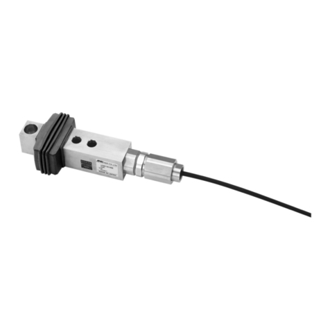
耐圧防爆型シングルポイントロードセル耐圧防爆型シングルポイントロードセル
耐圧防爆型シングルポイントロードセル耐圧防爆型シングルポイントロードセル
耐圧防爆型シングルポイントロードセル
LCB01/02LCB01/02
LCB01/02LCB01/02
LCB01/02 シリーズシリーズ
シリーズシリーズ
シリーズ
本社 本社
本社 本社
本社
〒〒
〒〒
〒170‑0013170‑0013
170‑0013170‑0013
170‑0013 東京都豊島区東池袋 東京都豊島区東池袋
東京都豊島区東池袋 東京都豊島区東池袋
東京都豊島区東池袋3‑23‑143‑23‑14
3‑23‑143‑23‑14
3‑23‑14((
((
(ダダ
ダダ
ダイイ
イイ
イハハ
ハハ
ハツツ
ツツ
ツ・・
・・
・
ニッセイ池袋ビルニッセイ池袋ビル
ニッセイ池袋ビルニッセイ池袋ビル
ニッセイ池袋ビル 5F5F
5F5F
5F))
))
)
TEL03‑5391‑6126TEL03‑5391‑6126
TEL03‑5391‑6126TEL03‑5391‑6126
TEL03‑5391‑6126((
((
(代代
代代
代))
))
)
FAX03‑5391‑6129FAX03‑5391‑6129
FAX03‑5391‑6129FAX03‑5391‑6129
FAX03‑5391‑6129
1.1.
1.1.
1.概要概要
概要概要
概要
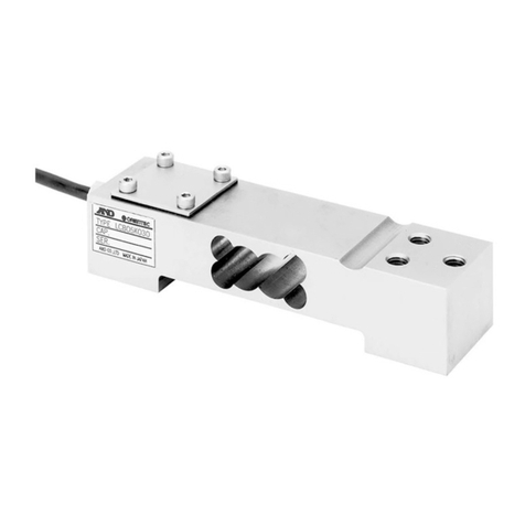
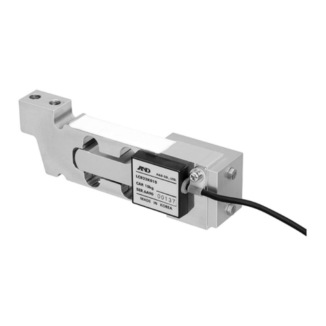
●LCB01/02シリーズは、耐圧防爆型シングルポイントロードセルで、可燃性危
険物を取り扱う工場や現場で計量、配合、充填用の計量台をシンプルに製作できま
す。適切な使用方法により、高精度なパフォーマンスが得られます。
●正しい設置を行うには静的な条件のみではなく、ショックや振動を含めたダイナミッ
クな面の検討も必要です。
2.2.
2.2.
2.仕様仕様
仕様仕様
仕様
定格容量 ............ 300,600,1500N 入力端子間抵抗 ................. 418Ω±20Ω
定格出力 .......... 0.3059mV/V±10% 出力端子間抵抗 ................ 348.5Ω±5Ω
最大許容過負荷 ..........150%OFR.C 絶縁抵抗 .................. 5000MΩ以上/DC50V
総合誤差 .............. 0.03%OFR.O ゼロ点の温度影響 .......... 0.05%OFR.O./10℃
ゼロバランス ......... 20±5%OFR.O. 出力の温度影響 ............ 0.03%OFLOAD/10℃
温度補償範囲 ......... −10℃〜40℃ 最大許容風袋荷重 .................33%OFR.C.
最大印加電圧 .................. 15V ケーブル太さ・長さ .................. 7×6m
防爆構造区分 ...................... ExdⅡBT4
3.3.
3.3.
3.設置にあたっての注意点設置にあたっての注意点
設置にあたっての注意点設置にあたっての注意点
設置にあたっての注意点
危危
危危
危
険険
険険
険
本機は本機は
本機は本機は
本機は「「
「「
「ExdExd
ExdExd
ExdⅡⅡ
ⅡⅡ
ⅡBT4BT4
BT4BT4
BT4」」
」」
」仕様の耐圧防爆電気機器であり、仕様の耐圧防爆電気機器であり、
仕様の耐圧防爆電気機器であり、仕様の耐圧防爆電気機器であり、
仕様の耐圧防爆電気機器であり、正しく設置が正しく設置が
正しく設置が正しく設置が
正しく設置が
行われない場合、行われない場合、
行われない場合、行われない場合、
行われない場合、爆発の危険性があります。爆発の危険性があります。
爆発の危険性があります。爆発の危険性があります。
爆発の危険性があります。設置作業は、設置作業は、
設置作業は、設置作業は、
設置作業は、防爆電気機防爆電気機
防爆電気機防爆電気機
防爆電気機
器設置作業の十分な知識を有した保守員以外の者の設置作業を禁じま器設置作業の十分な知識を有した保守員以外の者の設置作業を禁じま
器設置作業の十分な知識を有した保守員以外の者の設置作業を禁じま器設置作業の十分な知識を有した保守員以外の者の設置作業を禁じま
器設置作業の十分な知識を有した保守員以外の者の設置作業を禁じま
す。す。
す。す。
す。
3−3−
3−3−
3−11
11
1ベースへの設置
ベースへの設置
ベースへの設置ベースへの設置
ベースへの設置
(1)ベースは通常の使用状態で傾いたり、曲がったりしない強固なものでなければな
りません。ベースが曲がるとプラットホームが傾き悪影響が生じます。
(2)ベースは剛性の有るものを使用しロードセル取付面は表面あらさ25S(三角記
号で▽▽)以上が必要です。
(3)ロードセルのベースへの取付は4本の六角穴付ボルト(強度区分10.9相当)
または、ハイテンション六角ボルト(強度区分10.9相当)を使用し、締め付け
トルク及びねじ込み長さは表−1とします。また、一般的な市販ボルト(低引張強
度)の使用は避けてください。
表−1
(4)ボルトを締め付ける時は、ロードセルの固定側を押さえながら行ってく
ださい。
なお、ベーススペーサを使用する場合、取付面のゴミ等の付着を必ず取り除
いてください。(図−1参照)
3−2プラットホームの取付け3−2プラットホームの取付け
3−2プラットホームの取付け3−2プラットホームの取付け
3−2プラットホームの取付け
(1)プラットホームと風袋を含めた総重量が定格容量(以下R.C.)の150%
の範囲であれば十分な性能を発揮しますが、ロードセルの寿命を出来るだ
け長く、且つ高性能を維持するために風袋荷重はなるべく小さいものをお
勧めします。
(2)プラットホームは剛性の有るものを使用し、ロードセル取付面は表面あ
らさ25S(三角記号で▽▽)以上が必要です。
(3)プラットホームのロードセルへの取付は4本の六角穴付ボルト(強度区分
10.9相当)または、ハイテンション六角ボルト(強度区分10.9相
当)を使用し、締め付けトルク及びねじ込み長さは表−1とします。また、
一般的な市販ボルト(低引張強度)の使用は避けてください。なお、プラッ
トホームがアルミニウムか軟質金属である場合は、ボルトの圧縮荷重を分
散させる為に鉄製のワッシャーを使用してください。
(4)ボルトを締め付ける時は、ロードセルに不用な負荷(ひねり、横荷重等)が加わ
らないように注意してください。
なお、プラットホームスペーサを使用する場合、取付面のゴミ等の付着を必ず取り
除いてください。
(5)プラットホームの許容寸法は図−1を参照してください。
また、プラットホームの設計には過荷重に関する注意事項を参照してください。
1WMPD4000070A
EXPLOSION-PROOF TYPE SINGLE POINT BEAM LOAD CELL
LCB01/02SeriesLCB01/02Series
LCB01/02SeriesLCB01/02Series
LCB01/02Series
1.INTRODUCTION
LCB01/02 series are explosion-proof type single point beam load cells.
They are used to configure simplified weighing platforms for weigh-
ing, mixing and filling at a factory site handling flammables. Optimum
load cell performance is achieved through proper operation.
To install the load cell properly, the static conditions, as well as dy-
namic factors (i.e., shock and vibration) must be considered.
2.SPECIFICATIONS
Rated capacities .................................................................... 300,600,1500 N
Rated output....................................................................... 0.3059mV/V 10%
Maximum safe overload ............................................150% of rated capacity
Combined error ............................................................. 0.03% of rated output
Zero balance................................................................ 20 5% of rated output
Compensated temperature range.......................................................-10~40
Maximum excitation voltage ..................................................................... 15V
Input terminal resistance.................................................................. 418 20
Output terminal resistance .............................................................. 348.5 5
Insulation resistance .................................... Greater than 5000M at 50VDC
Temperature effect on zero ................................. 0.05% of rated output/ 10
Temperature effect on span .......................................... 0.03% of LOAD/ 10
Maximum permissible tare ...........................................33% of rated capacity
Cable length ........................................................................................ 76m
Explosion-proof class ......................................Exd BT4 (Japanese standard)
3.NOTESONINSTALLATION
DANGER
This load cell is an explosion-proof type electrical device
and conforms to “Exd BT4” (Japanese standard). Install it
properly, or it may cause an explosion. Only those who
have an adequate knowledge of the installation of explo-
sion-proof type electrical devices are to be allowed to in-
stall it.
3-1 INSTALLING ON A BASE
(1) The base should be rigid to prevent it from slanting or curving under
normal operating conditions.
If the base yields, the platform will bend and adversely affect the load
cell.
(2) Use a highly rigid base. The mounting surface for the load cell re-
quires a surface finish of 25S (JIS*) or more.
*JIS=Japan Industrial Standard
(3) Use four hexagon socket head bolts (tensile strength Class 10.9-JIS
or equivalent) or high-tension hexagon head bolts (tensile strength
Class 10.9-JIS or equivalent) to mount the load cell on the base. Table
1 lists the applicable clamping torque and screw-in depth. Be sure to
avoid using ordinary bolts (of a lower tensile strength) available on
the market. Table 1
(4) Tighten the bolts while holding the mounting side of the load cell.
If a base spacer is used, make sure that the attaching surface is
clean and free from foreign matter.
3-2 ATTACHING THE PLATFORM
(1) When the total platform weight with load is less than 150% of the
rated capacity, the load cell provides optimum performance. The total
load should be as light as possible to prolong the service life and
excellent performance of the load cell.
(2) Use a platform fixture with high rigidity. The mounting surface re-
quires a surface finish of 25S (JIS) or more.
(3) Use four hexagon socket head bolts (tensile strength Class 10.9-JIS or
equivalent) or high-tension hexagon head bolts (tensile strength Class
10.9-JIS or equivalent) to attach the platform fixture to the load cell.
Table 1 lists the applicable clamping torque and screw-in depth.Avoid
using ordinary bolts (of low tensile strength) available on the market.
If the platform fixture is made of aluminum or other non-rigid metals, use
a steel washer to disperse the compressive load applied by the bolts.
(4) Tighten the bolts so that unnecessary force (torsion or lateral load) is not
applied to the load cell.
Clean the attaching surfaces of the platform spacer, if used.
(5) For the allowable dimensions of the platform, see Figure 1. Also,
when designing a platform, see the "OVERLOAD PRECAUTIONS" on
the next page.

