A&D SV-1A User manual

SV-A series
-Stand Type-
SV-H series
-Portable Type-
Vibro Viscometer
INSTRUCTION MANUAL
1WMPD4001459A

© 2008 A&D Company Ltd. All rights reserved.
No part of this publication may be reproduced, transmitted, transcribed, or translated
into any language in any form by any means without the written permission of A&D
Company Ltd.
The contents of this manual and the specifications of the instrument covered by this
manual are subject to change for improvement without notice.

1
CONTENTS
1. INTRODUCTION .............................................................................................................................3
1-1 Compliance......................................................................................................................................... 3
Compliance with FCC Rules ................................................................................................................. 3
Compliance with Council Directives...................................................................................................... 3
1-2 Features ............................................................................................................................................. 5
2. UNPACKING THE VISCOMETER ..................................................................................................7
2-1 Part names for the SV-A series (Stand type)...................................................................................... 7
2-2 Part names for the SV-H series (Portable type) ............................................................................... 13
3. CHANGING TYPE ..........................................................................................................................16
3-1 Changing from SV-A (Stand type) to SV-H (Portable type).....................................................................16
3-2 Changing from SV-H (Portable type) to SV-A (Stand type)..................................................................... 17
4. DISPLAY AND KEYS ....................................................................................................................20
4-1 Display.............................................................................................................................................. 20
4-2 Keys (For all models)........................................................................................................................ 21
4-3 Displaying the Viscosity Values ........................................................................................................ 22
4-3-1 SV-1A/SV-1H ............................................................................................................................. 22
4-3-2 SV-10A/SV-10H ......................................................................................................................... 23
4-3-3 SV-100A/SV-100H ..................................................................................................................... 23
5. PRECAUTIONS ............................................................................................................................24
5-1 General Precautions (For all models)............................................................................................... 24
5-2 Precautions for an Acurate Measurment (Only for the SV-H series)................................................ 24
5-3 During Use (For all models) ............................................................................................................. 25
5-4 After Use (For all models)................................................................................................................. 26
5-5 Measuring the Absolute Value of Viscosity (For all models) ..................................................................... 27
5-5-1 At Measurement ........................................................................................................................ 27
5-5-2 At Calibration ............................................................................................................................. 27
6. MEASUREMENT ..........................................................................................................................28
6-1 Preparing the Sample (For the SV-A series) .................................................................................... 29
6-2 Basic Measurement Procedure (For the SV-A series) ..................................................................... 32
6-3 Basic Measurement Procedure (For the SV-H series) ..................................................................... 33
6-4 Changing Units (For all models)....................................................................................................... 36
7. USING THE WATER JACKET ......................................................................................................37
7-1 . Introduction..................................................................................................................................... 37
7-2 . Installation ...................................................................................................................................... 38
7-3 . How to Use ..................................................................................................................................... 40
7-4 . Measuring the Absolute Value of Viscosity Using the Small Sample Cup.................................................. 41
7-5 . Maintenance ................................................................................................................................... 41
7-6 . Specifications.................................................................................................................................. 41

2
8. VISCOSITY CALIBRATION (FOR ALL MODELS) .......................................................................42
8-1 Notes on Viscosity Calibration (For all models)................................................................................ 43
8-2 Calibration Procedure (For all models)............................................................................................. 44
8-2-1 One-point Calibration................................................................................................................. 45
8-2-2 Two-point Calibration................................................................................................................. 46
8-2-3 Simplified Calibration Using Purified Water (SV-1A/1H/10A/10H) ............................................ 48
9. FUNCTION SETTING (FOR ALL MODELS) ................................................................................50
9-1 Operation (For all models)................................................................................................................ 50
9-2 Details of the Function Items (For all models).................................................................................. 52
9-3 Description of Items (for all models) ................................................................................................. 54
9-4 Data Output Format Examples (For all models)............................................................................... 64
9-4-1 A&D Standard Format................................................................................................................ 64
9-4-2 D.P. Format................................................................................................................................ 66
9-4-3 CSV Format ............................................................................................................................... 67
9-4-4 RsVisco Format ......................................................................................................................... 71
10. CONNECTION TO A PERSONAL COMPUTER.........................................................................74
10-1 Introduction ..................................................................................................................................... 74
10-2 Installation of WinCT-Viscosity ....................................................................................................... 74
10-3 Connection to a personal computer................................................................................................ 75
10-4 Configuration of the COM port........................................................................................................ 76
10-5 Controlling the measurement using a personal computer.............................................................. 77
11. CONNECTION TO A PRINTER (FOR ALL MODELS)................................................................78
12. RS-232C SERIAL INTERFACE (FOR ALL MODELS) ...............................................................79
13. COMMAND LIST (FOR ALL MODELS)......................................................................................80
14. TROUBLESHOOTING (FOR ALL MODELS) .............................................................................81
14-1 When measurement values do not become stable (For all models)........................................................ 81
14-2 When measurement values are not correct (For all models)............................................................ 83
14-3 When more precise measurement is required: (For all models) ........................................................... 84
14-4 When the temperature values are not correct (For all models)............................................................. 84
14-5 When water viscosity is to be measured (Only for SV-1A/1H/10A/10H)........................................................... 84
15. ERROR DISPLAY (FOR ALL MODELS) ....................................................................................85
16. SPECIFICATIONS.......................................................................................................................86
17. OPTIONAL ACCESSORIES .......................................................................................................88
18. EXTERNAL DIMENSIONS .........................................................................................................98

3
1. INTRODUCTION
This manual describes how the SV-A/SV-H series viscometer works and how to get the most out of it
in terms of performance.
Read this manual thoroughly before using the viscometer and keep it at hand for future reference.
The SV-A series uses a stand. In a laboratory, quality control room etc, you can make accurate
measurements using the stand set, the sample cup set and the software set provided.
The SV-H series uses a handle only. While at a manufacturing location, you can make a
measurement easily. If you buy the accessories, the SV-H series functions the same as the SV-A
series.
1-1 Compliance
Compliance with FCC Rules
Please note that this device generates, uses and can radiate radio frequency energy. This
device has been tested and has been found to comply with the limits of a Class A computing
device pursuant to Subpart J of Part 15 of FCC rules. These rules are designed to provide
reasonable protection against interference when this device is operated in a commercial
environment. If this unit is operated in a residential area, it may cause some interference and
under these circumstances the user would be required to take, at his own expense, whatever
measures are necessary to eliminate the interference.
(FCC = Federal Communications Commission in the U.S.A.)
Compliance with Council Directives
This device features radio interference suppression and safety regulation in compliance with
the following Council Directives
Council directive 89/336/EEC EN61326 EMC directive
Council directive 73/23/EEC EN60950
Safety of Information Technology Equipment
EN61326 Emission and Immunity.
Note
The CE mark is an official mandatory European marking.
Please note that any electronic product must comply with local laws and regulations when
sold or used anywhere outside Europe.

4

5
1-2 Features
High accuracy
The Vibro Viscometer adopting the sine-wave vibration technique (SV type), achieves a high
measurement accuracy of 1%*1 (repeatability) over the full range.
*1 With the SV-H series, when using the AX-SV-51 stand set (sold separately).
Refer to "16. SPECIFICATIONS" on page 86.
Measurement of a small amount of sample
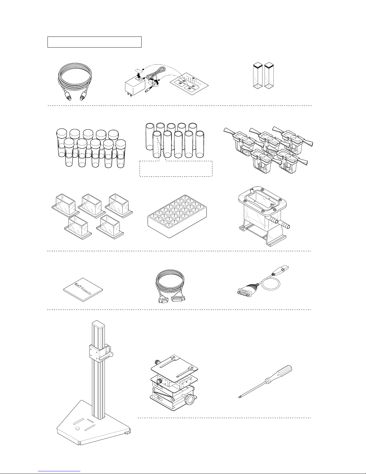
The SV-1A can measure with a 2 mL sample (minimum amount), and the standard X-Y-Z
stage can position the sample container easily.
When using the accessory items (sold separately), the SV-1H can measure with stability a 2
mL sample (minimum amount). For details, refer to "17. OPTIONAL ACCESSORIES"
With the SV-H series, you can measure the viscosity at the manufacturing location by using
the standard carrying case.
The sensor plates are made of corrosion resistant titanium. Although titanium is a chemically
stable material, it is corroded by some liquid such as sulfuric acid. So, handle it with much
care.
Wide range continuous measurement
Continuous measurement over the whole measuring range is possible, without replacing the
viscosity detection sensor plates.
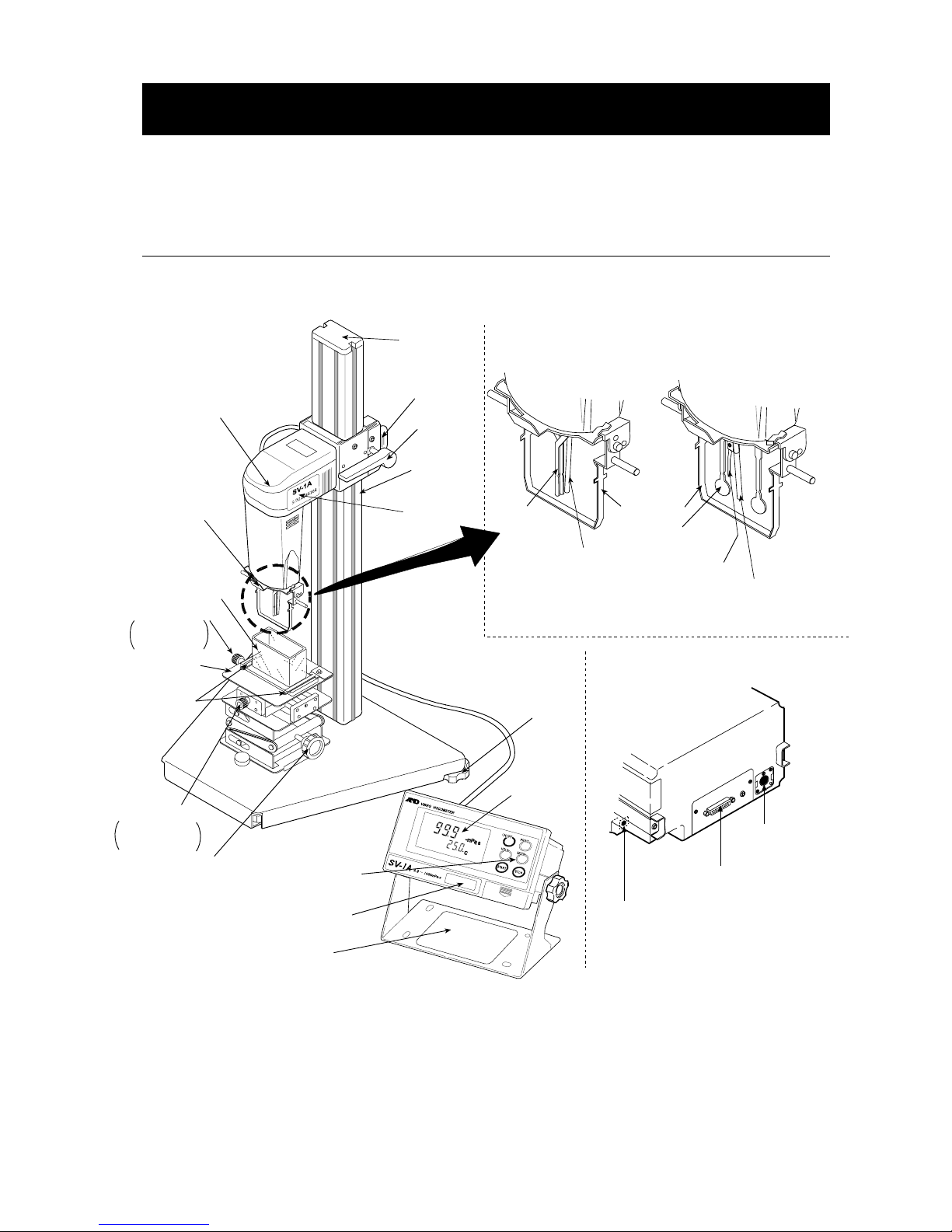
Standard temperature sensor
The temperature sensor to measure the sample temperature is installed as standard. With
SV-1A/1H, the temperature sensor is located behind the two sensor plates. With the
SV-10A/10H/100A/100H, the temperature sensor is located between the two sensor plates. So,
the accurate detection of the relation between temperature and viscosity is possible.
Accurate measurement
Due to the low heat capacity of the viscosity detection unit (sensor plates and temperature
sensor), the time required for temperature equilibrium is short. Thus, the sample viscosity can
be measured accurately in a short time.
Long continuous measurement time
The sensor plates, with a low frequency of 30 Hz and an amplitude of less than 1 mm, apply
very little load to the sample. So, the viscometer can continuously obtain stable viscosity
values without causing a temperature rise or damaging the sample. With the SV-H series, use
the AX-SV-53 Software set-WinCT Viscosity (sold separately).
Measurement of a non-Newtonian fluid/foaming sample
The thin sensor plates allow little deformation of the sample texture. Thus, non-Newtonian fluid
can be measured in a stable way. And, foaming samples can be measured without breaking
minute foam particles and with less influence scattering large foam particles.
When measuring tap water, bubbles may accumulate on the sensor plates, increasing the
viscosity.
Viscosity measurement of a flowing sample
The two sensor plates oscillate in the opposite direction. So, even when a sample is in motion,
errors are eliminated. This allows measurement of a sample while being stirred. Therefore, the
viscometer can be used for a continuously flowing product line, which enables field
management with identical data used at the laboratories.

6
Calibration
The viscometer can be calibrated using a standard viscosity fluid or a sample of a known
viscosity. Calibration allows the viscometer to maintain the accuracy constantly.
In case of a Newtonian fluid, by calibrating an actual sample, using the viscosity value
obtained by another type of viscometer as a correction value, the measurement data obtained
by the SV-A/SV-H series viscometer can be combined into those obtained by the other type of
viscometer.
The vibro viscometer and the capillary viscometer and the rotational viscometer are a type of
calibration equipment for viscosity measurement by JCSS standard (Japan Calibration Service
System).
Simplified calibration when measuring the viscosity near 1 mPa⋅s (Only for SV-1A/1H/
10A/10H)
Simplified calibration using purified water is a one-key operation. The SV-1A/1H/10A/10H has
a built-in function to measure the temperature of the purified water using the temperature
sensor and calculates the viscosity value of the purified water at that temperature.
At this time, be careful not to influence the viscosity value by generating bubbles.
Standard windows communication tools WinCT-Viscosity (With the SV-A series, it is standard
accessory. With the SV-H series, it is sold separately (AX-SV-53-EX))
Windows communication tools WinCT-Viscosity (CD-ROM) is provided as standard. The
CD-ROM contains the graphing program RsVisco, which imports the data into a personal
computer and displays the results as a graph in real time. With RsVisco, changes in viscosity
over time and temperature dependency of viscosity can be observed easily and the obtained
data can be saved in files.
When using the accessory serial / USB converter, the personal computer can input the data
using the personal computer’s USB port. (With the SV-A series, it is standard accessory. With
the SV-H series, it is sold separately (AX-SV-53-EX))
The cup, that the sample is to be measured in, can be the plastic sample cup and the glass
sample cup. When measuring an organic solvent, use the glass sample cup.
Use the carrying case only for carrying the viscometer. Do not transport the viscometer using
the carrying case. Doing so may cause damage to the viscometer. When transporting the
viscometer, be sure to use the original packing material.

7
2. UNPACKING THE VISCOMETER
The viscometer is a precision instrument. Unpack the viscometer carefully. Keep the packing
material to be used for transporting the viscometer in the future.
2-1 Part names for the SV-A series (Stand type)
*The illustration below is after assembling.
Lever
Guides
Sample cup
Ta b l e
knob
Main unit
Display unit
Display
Keys
Sensor unit
Sensor protective
cover
Cap
Supporting
post
Surface locator
plate
AC adapter jack
RS-232C serial interface
Connection
cable jack
Display unit
rear side
Right and left
direction
knob
Back and forth
direction
knob
(Height direction)
Serial number
Serial number
Leveling foot
Reference card
Temperature sensor
Grip
Protector
Sensor
plate
SV-1A
SV-10A/SV-100A
S/N12345164
Temperature sensor
Sensor
plate

8
Windows communication tools
WinCT-Viscosity(CD-ROM) (1 pc)
Sample cup (Lid attached)
(Polycarbonate, Capacity: 2 mL,
10 pcs)
Water jacket (1 pc)
Connection cable (1 pc)
RS-232C cable (1 pc)
25P-9P for modem
AC adapter (1 pc) AC adapter label
Serial-USB converter (1 pc)
Stand for securing the sensor unit (1 pc)
X-Y-Z stage (1 pc)
Glass sample cup
(Capacity: 2 mL, 10 pcs)
Sample cup holder
(Polycarbonate, For 2 mL capacity,
Transparent: 3 pcs, Black: 2 pcs)
Sample cup
(Polycarbonate, Capacity: 45 mL,
5 pcs) Sample cup stand
(For 2 mL capacity, 1 pc)
* The lid for the sample cup
(2 mL) does not fit this cup.
Screwdriver (1 pc)
Can be used for
optical measuring devices
Square glass sample cup
(10 mm x10 mm x 45 mm)
Accessories for SV-1A
Note
Please confirm that the AC adapter type is correct for
your local voltage and receptacle type.
See the note below.

9
Accessories for SV-10A / SV-100A
.
Note
Please confirm that the
A
C adapter type is correct
for your local voltage and
receptacle type.
Windows communication tools
WinCT-Viscosity(CD-ROM) (1 pc)
Water jacket (1 pc)
Connection cable (1 pc)
RS-232C cable (1 pc)
25P-9P for modem
AC adapter (1 pc) AC adapter label
Serial-USB converter (1 pc)
Stand for securing the sensor unit (1 pc)
X-Y-Z stage (1 pc)
Glass sample cup
(Capacity: 13 mL, 2 pcs)
Small sample cup cover
(Polycarbonate, 5 pcs)
Sample cup
(Polycarbonate, Capacity: 45 mL,
5 pcs)
Glass sample cup holder
(1 pc)
Small sample cup
(Polycarbonate, Capacity: 10 mL,
5 pcs)
The position about 25 mm
above the cup bottom
indicates 13 mL.
Screwdriver (1 pc)

10
Unpacking
Sample cup
stand (1 pc)
Glass sample
cup[2ml] (10 pcs)
Sample cup
[2ml](10 pcs)
Lid
(10 pcs)
Water jacket
(1 pc)
Sample cup holder
[For 2ml] ( 5 p cs ) *
Sample cup
[45ml] ( 5 p c s )
Small sample
c u p [10ml] ( 5 p c s )
Glass sample
cup holder
[For 13ml] ( 1 p c )
Glass sample
cup
[13ml] ( 2 p c s )
SV-1A SV-10A / SV-100A
* Transparent
-
3 pcs,
Black-2 pcs
Sample cup
[45ml] ( 5 p c s )
Water jacket
(1 pc)
Small sample
c u p cover ( 5 p c s )
Lid
(2 pcs)
X-Y-Z stage Slider
Connection
cable
Display
AC adapter
Stand
Protector
Sensor unit
Handle the sensor plate
with care.
Instruction
manual
Knobs for securing
the display
Screwdriver
Square glass sample cup
(2 pcs)
Supporting post
Base

11
Assembling
Note: When assembling, handle the sensor plates
with care.
When removing or tightening the screws
located on the rear side of the sensor unit’s
handle, use the screwdriver that is provided
with the viscometer.
1 Remove the two screws from the bottom of the
supporting post. Install the supporting post onto
the base. From the underside of the base, secure
the post using the two screws previously
removed.
2 Remove the attachment screw from the base.
Install the X-Y-Z stage along the guide ribs from
forward of the base. Secure the X-Y-Z stage using
the screw removed. (Confirm the direction of the
X-Y-Z stage’s knobs.)
3 Install the protector on the sensor unit of the
SV-1A/SV-10A/ SV-100A.
Insert the protector’s rotational axis into the
sensor unit’s hole.
(Refer to the figure at the right.)
4 Remove the four screws from the
rear side of the sensor unit’s handle.
Using the four screws removed,
attach the sensor unit to the slider.
Tighten the screws completely, using
the screwdriver provided with the
viscometer, so that there will be no
measurement error due to movement
of the head.
Sensor
plate
Sensor unit
Example: SV-1A
Protector
1
Rotational
axis
2
1
3
3
Rotational
axis
Screws
Base
Supporting post
Screw
Install from forward
X-Y-Z stage
Slider
Screws
Screwdriver

12
Connection cable
from the display unit
(Connect as shown)
Main unit
Guide channel
Serial number
Lever
Cap
Handle the sensor
plates with care.
5 Raise the lever and install the sensor unit along
the guide channels of the supporting post’s
sides.
At an appropriate height, secure the sensor unit
to the supporting post by lowering the lever.
6 Confirm that the stand’s mounting holes and the
display’s mounting holes match up. Secure both
sides of the display with the knobs.
7 Connect the display unit to the main unit using the
connection cable.
8 Insert the AC adapter plug into the AC
adapter jack located on the rear side of the
display unit. Insert the other end of the AC
adapter plug into an electrical outlet.
Serial number
Knob for securing
the display
Stand
Display
Knob for
securing
the display
AC adapter cable
Display unit
rear side
Connection cable
from the main unit
(Connect as shown)
Note:
•Confirm that the adapter type is correct fo
r
the local voltage and power receptacle type.
•The main unit and the display unit have been
adjusted in pairs. For accurate viscosit
y
measurement, before use, confirm that the
main unit and the display unit have the same
serial number.

13
2-2 Part names for the SV-H series (Portable type)
A
ccessories
Note
Please confirm that the AC adapter type is correct for your local
voltage and receptacle type.
Connection cable (1 pc) AC adapter (1 pc) AC adapter label
S/N12345164
Handle
Senso
r
unit
Sensor protective
cove
r
Temperature
sensor
Protector
Senso
r
p
late
Display
Reference card
Display unit
Display unit
rear side
Connection
RS-232C serial interface
A
C adapter jack
Main
unit
Keys
Senso
r
p
late
Temperature
sensor
SV-1H SV-10H/SV-100H
Surface
locator plate
Serial number
Serial
number

14
Unpacking / Assembling
Note: When assembling, handle the sensor plates with care.
1 Unpack the parts from the carrying case.
2 Install the protector on the sensor unit of the SV-1H/SV-10H/SV-100H.
Insert the protector’s rotational axis into the sensor unit’s hole.
(Refer to the figure at the right.)
3 Connect the display unit to the main unit using the connection
cable.
Note
The main unit and the display unit have been adjusted in
pairs. For accurate viscosity measurement, before use,
confirm that the main unit and the display unit have the
same serial number.
Connection cable
from the display unit
(Connect as shown)
Serial number
Sensor plate
Sensor
plate
Sensor unit
Example: SV-1H
Protector
1
Rotational
axis
2
1
3
3
Rotational
axis
Connection
cable
Display
AC adapter
Stand
Protector
Sensor unit
Handle the sensor plates
with care.
Instruction
manual
Knobs for securing
the display

15
4 Confirm that the stand’s mounting holes and the
display’s mounting holes match up. Secure both
sides of the display with the knobs.
5 Insert the AC adapter plug into the AC adapter
jack located on the rear side of the display unit.
Insert the other end of the AC adapter plug into
an electrical outlet.
Note
Confirm that the adapter type is correct for the
local voltage and power receptacle type.
AC adapter cable
Connection cable
from the main unit
(Connect as shown)
Display unit
rear side
Serial number
Knob for securing
the display
Stand
Display
Knob for
securing
the display

16
3. CHANGING TYPE
3-1
Changing from SV-A (Stand type) to SV-H (Portable type)
In the case that you have purchased an SV-A series (stand type), and you need to use it as a
portable type, make the following changes.
Note: When removing or tightening the screws,
use the screwdriver that is provided
with the viscometer.
1 Remove the four screws from the
rear side of the sensor unit’s slider.
Using the four screws removed,
attach the sensor unit to the handle.
Change the function setting of “5vtyp”from “atype”to“Htype”as follows:
* Even if the function setting of “5vtyp”is not changed, you can still use the viscometer. However,
the portable functions, H-fnc,5t-b,Hld-t,Cp,bep,Cp Hi and Cp lo will not be available.
2 Insert the AC adapter plug into the AC adapter
jack located on the rear side of the display unit.
Insert the other end of the AC adapter plug into an
electrical outlet.
3 Press the ON:OFF key to turn the power on.
4 While in the standby mode, press and hold the MODE
key for two or more seconds. The viscometer will
enter the function mode 5vtyp .
5 Press the PRINT key to select this item.
AC adapter cable
Display unit
rear side
(Standby mode)
Press and
hold
Continued on next page
Screws
Screws
Handle
Screwdriver provided
with the viscomete
r

17
Screws
Base
Supporting post
6 Press the START or HOLD key to display
Htype .
7 Press the PRINT key to store the setting.
After the viscometer displays end , it display the
next item of the function setting.
8 Press the STOP key to return to the standby mode.
If you need other functions of the portable type, refer to
“9. FUNCTION SETTING”.
3-2
Changing from SV-H (Portable type) to SV-A (Stand type)
In the case that you have purchased an SV-H series (portable type), and you need to use it with the
stand set, prepare the following accessories and make the following changes.
- AX-SV-51 Stand set
- AX-SV-53-EX Software set
- AX-SV-54 Sample cup set (10 mL/13 mL/45 mL)
- AX-SV-55 Sample cup set (2 mL) Only for SV-1A/SV-1H
Note: When removing or tightening the screws located on the rear side of the sensor unit’s
handle, use the screwdriver that is provided with the viscometer.
1 Remove the two screws from the bottom of
the supporting post. Install the supporting
post of the stand set onto the base. From the
underside of the base, secure the post using
the two screws previously removed.
Next item of
function setting
(Standby mode)
or
From the previous page

18
2 Remove the attachment screw from the
base. Install the X-Y-Z stage along the guide
ribs from forward of the base. Secure the
X-Y-Z stage using the screw removed.
(Confirm the direction of the X-Y-Z stage’s
knobs.)
3 Remove the four screws from the
rear side of the sensor unit’s
handle.
Using the four screws removed,
attach the sensor unit to the slider.
4 Raise the lever an d install the sensor unit along
the guide channels of the supporting post’s
sides.
At an appropriate height, secure the sensor
unit to the supporting post by lowering the
lever.
Change the function setting of “5vtyp”from “Htype”to “atype”as follows:
* Even if the setting of “5vtyp” is not changed, you can still use the viscometer. However, the
portable functions, H-fnc,5t-b,Hld-t,Cp,bep,Cp Hi and Cp lo remain available.
Slider
Screws
Screwdriver
Screw
Install from forward
X-Y-Z stage
Guide channel
Serial number
Lever
Handle the sensor
plate with care.
This manual suits for next models
7
Table of contents
Other A&D Analytical Instrument manuals

A&D
A&D AD-8951 User manual

A&D
A&D SV-10 User manual

A&D
A&D LCC12T010 User manual

A&D
A&D LC-1216-K100 User guide

A&D
A&D LC-4001-G120 User guide

A&D
A&D LCB05 Series User manual

A&D
A&D LCB03 Series User manual

A&D
A&D Vibratory spoon AD-1651 User manual

A&D
A&D LCB04 Series User manual

A&D
A&D LC-1205-K020 User guide
Popular Analytical Instrument manuals by other brands

Bosch
Bosch GLM Professional 80 plus R60 Original instructions

Teledyne
Teledyne 2020 operating instructions

YOKOGAWA
YOKOGAWA Vigilantplant NFBU200-S Series user manual

PCE Health and Fitness
PCE Health and Fitness PCE-IVM 3D user guide

Southland
Southland OMD-501D instruction manual

Teledyne
Teledyne T3AWG3K Series Operator's manual