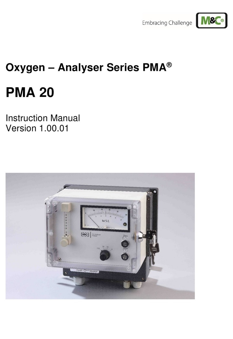
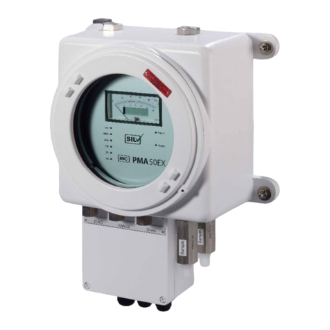
M&C GENTWO PMA1000 User manual

GENTWO®
Oxygen Analyzer
PMA1000 / PMA1000L
Instruction Manual
Version 1.00.00
Software Version: 2.00

1PMA1000/PMA1000L | 1.00.00 www.mc-techgroup.com
Get help
For more information about using your M&C product, please contact
M&C TechGroup. We will answer your questions about commissioning,
handling and technical service. With our experience and know-how, we
will get your M&C product running in no time - and with no charge.
Please contact our service center in Ratingen, Germany,
for US Service Ventura, California
For faster service, please have this information ready when you contact
us:
Product model
Product serial number
M&C order or invoice number
Germany service center:
+49 2102 935 - 888
US service:
+1 805-654-6970
info[email protected]om
For online service and support information go to:
www.mc-techgroup.com

2PMA1000/PMA1000L | 1.00.00 www.mc-techgroup.com
Get help
For more information about using your M&C product, please contact
M&C TechGroup. We will answer your questions about commissioning,
handling and technical service. With our experience and know-how, we
will get your M&C product running in no time - and with no charge.
Please contact our service center in Ratingen, Germany,
for US Service Ventura, California
For faster service, please have this information ready when you contact
us:
Product model
Product serial number
M&C order or invoice number
Germany service center:
+49 2102 935 - 888
US service:
+1 805-654-6970
info-usa@mc-techgroup.com
For online service and support information go to:
www.mc-techgroup.com
Table of Contents
1 About this instruction manual 6
2 Important safety information 7
2.1 Intended use 7
2.2 Personal safety 7
2.3 Warning signs and definitions 7
2.4 Safety instructions 9
2.5 Working on electrical and electronic devices 9
2.6 Not certified in hazardous areas 10
3 Introduction 11
4 Product overview 12
4.1 Receiving the analyzer 13
4.2 Product label and serial number 13
5 Measuring principle of the analyzer 14
5.1 Principle of measurement 14
5.2 Flow chart 16
6 Technical data 17
6.1 Dimensions 18
6.2 Connections 19
6.3 Components 20
6.3.1 Sensor module 20
6.3.2 I/O module 21
6.4 Gas connections and pin assignment diagram 22
7 Using the analyzer 24
7.1 Graphical user interface (GUI) 24
7.2 How to use the touch screen 24
7.3 Menu structure 25
7.3.1 System status line 26
7.3.2 Main menu bar 27
7.3.3 Main display area 28
7.3.4 Language selection 28
7.3.5 M1/S1 and M1/S2 - M&C contact and GUI version number 29
7.3.6 M1/S3 - Pneumatic connections 31
7.3.7 M1/S4 - Operating hours counter 31
7.3.8 M2/S1, M2/S2 - Measured values, operating parameters and limits 31
7.3.9 M2/S3 - List view of the measured values 34
7.3.10 M3/S1 - Data logger/history archive 34
7.3.11 M4/S1 - Measuring range selection and parameter settings 36
7.3.12 M4/S2 - Settings menu/ parameters 39
7.3.13 M5/S1 and M5/S2 calibration menu 53
7.3.14 M6/S1 Help button 55

3PMA1000/PMA1000L | 1.00.00 www.mc-techgroup.com
8 Mounting and installation 56
8.1 General 56
8.2 Installation examples 56
9 Starting-up and operating the analyzer 58
9.1 General 58
9.2 Start-up and operation 58
10 Calibration 60
10.1 General 60
10.2 M5/S1 Manual Calibration 60
10.3 Automatic Calibration (AutoCal) 66
10.4 Calibration of auxiliary variables 75
10.5 Cross-sensitivity of coexisting gases 76
11 Service and maintenance 79
11.1 Recommended maintenance work 79
12 Spare parts and consumables 80
13 Appendix 81
13.1 Trouble shooting 81
13.2 Additional Information 81
13.3 Declaration of conformity 81
13.4 Certificates 82
13.5 Warranty 82
13.6 Liability and disclaimer 82
13.7 Storage 83
13.8 Shipping and handling 83
13.9 Proper disposal of the device 83
14 About us 84
14.1 M&C‘s group of companies 84
14.2 The quality-oriented M&C catalog 85
14.3 Technical consulting services 86
14.3.1 Ideas, suggestions and feedback 86

4PMA1000/PMA1000L | 1.00.00 www.mc-techgroup.com
Table of Illustrations
Fig. 1: Product label is on the back of the PMA1000/PMA1000L 13
Fig. 2:Paramagnetic measuring cell 14
Fig. 3:Electronic evaluating system to measure oxygen concentration 15
Fig. 4:Flow chart 16
Fig. 5:Enclosure front view 18
Fig. 6:Enclosure side view 19
Fig. 7:Rear view PMA1000 19
Fig. 8:Inside view PMA1000 20
Fig. 9:Sensor module 20
Fig. 10: I/O module 21
Fig. 11: Gas connections and pin assignment diagram 22
Fig. 12: Startup screen of the 1-Channel configuration 24
Fig. 13: Menu structure overview 26
Fig. 14: System status line 27
Fig. 15: Menu bar with the menu items M1 to M6 27
Fig. 16: Main display area 28
Fig. 17: Language selection window 29
Fig. 18: M1/S1 - M&C contact information 29
Fig. 19: Swipe to navigate through the sections 29
Fig. 20: M1/S2 - Analyzer configuration 30
Fig. 21: Detailed information about the GUI software version 30
Fig. 22: M1/S3 - Pneumatic connections of the analyzer 31
Fig. 23: M1/S4 - Operating hours counter (OHC) 31
Fig. 24: M2/S1 - Start screen of the home button 32
Fig. 25: M2/S2 - Detailed view of the measuring parameters 32
Fig. 26: M2/S2 - Detailed view during warm-up period 33
Fig. 27: M2/S2 - Using the zoom button 33
Fig. 28: Zoomed and highlighted area 33
Fig. 29: M2/S3 - List view of the measured values 34
Fig. 30: M3/S1 data logger screen 35
Fig. 31: M3/S1 - Recorded data selection screen 35
Fig. 32: Calibration symbols to highlight calibration procedures 36
Fig. 33: M4/S1 Edit buttons for measuring range and operating parameter settings 36
Fig. 34: Highlighted scroll bar to select measuring range 37
Fig. 35: Parameter list 37
Fig. 36: Highlighted scroll bar to set operating parameter Lim1 38
Fig. 37: Highlighted scroll bar to set operating parameter Lim2 38
Fig. 38: M4/S2 screen with ‘Restart’ button 39
Fig. 39: M4/S2 Settings menu and parameter screen 40
Fig. 40: Basic settings for channel 1 41
Fig. 41: Keypad 41
Fig. 42: Channel-specific settings list 42
Fig. 43: After selecting ‘2 = System’, the screen with system settings opens 45
Fig. 44: Scroll bar with ‘4=Updates’ displayed in the gray frame 46

5PMA1000/PMA1000L | 1.00.00 www.mc-techgroup.com
Fig. 45: Buttons to get information and install hardware and software updates 46
Fig. 46: Screen to confirm the update of the application software 47
Fig. 47: M4/S2 screen with ‘Factory reset’ selected 47
Fig. 48: Default setting menu with four parameters to select 48
Fig. 49: Database import and export settings 48
Fig. 50: IP address input screen 49
Fig. 51: Date and time settings 49
Fig. 52: Supervisor settings for administrators 50
Fig. 53: Download a new PDF-file with the latest manual version 50
Fig. 54: Scroll bar with ‘B=Diagnosis’ displayed in the gray frame 51
Fig. 55: Schematic for diagnosis 51
Fig. 56: Display of the High-Side- and relay-outputs with the mA-output of I/O2 52
Fig. 57: Display of the highlighted SM2 components 52
Fig. 58: Scroll bar with ‘C=Service’ displayed in the gray frame 53
Fig. 59: Gas calibration screen 53
Fig. 60: Calibration of pressure gauges and flow sensor 54
Fig. 61: Help button screen 55
Fig. 62: Example: Span gas calibration with sample gas pump 57
Fig. 63: Example: Span gas calibration with calibration gas from a pressure cylinder 57
Fig. 64: Warm-up phase in M2/S1 and warm-up info on M2/S2 59
Fig. 65: Analyzer is ready to operate 59
Fig. 66: Manual calibration PMA1000L 60
Fig. 67: Setting the channel-specific calibration parameters 61
Fig. 68: Manual calibration with span gas 61
Fig. 69: First step of the manual calibration procedure 62
Fig. 70: Second step of the manual calibration procedure 62
Fig. 71: Third step of the manual calibration procedure 63
Fig. 72: End of the manual calibration procedure 63
Fig. 73: Data logger screen with green calibration symbol 64
Fig. 74: A terminated manual calibration procedure 64
Fig. 75: Manual calibration error 65
Fig. 76: Datalogger screen with red calibration symbol 65
Fig. 77: Screen showing details about a single calibration procedure 66
Fig. 78: AutoCal activation: open section M4/S2 67
Fig. 79: AutoCal activation: change system settings (first part of the list) 67
Fig. 80: AutoCal activation: change system settings (second part of the list) 68
Fig. 81: Scroll to ‘AutoCal’ to reach calibration start screen 69
Fig. 82: AutoCal start screen 69
Fig. 83: Parameter screen to adjust test gas measuring ranges and concentrations 70
Fig. 84: Tap on Start button to start AutoCal procedure 70
Fig. 85: Information displayed during AutoCal procedure 71
Fig. 86: Canceled AutoCal process 74
Fig. 87: Calibration of pressure gauges and flow sensor 75
Fig. 88: Formula to calculate the effects of coexisting gases 77
Fig. 89: Instruction manual available in PDF-format 81

6PMA1000/PMA1000L | 1.00.00 www.mc-techgroup.com
1 About this instruction manual
Welcome to the M&C product manual. The goal of this document is to give a broad over-
view of the main functions of the PMA1000/PMA1000L. It will help you to get started with
using the GENTWO analyzer.
If you have any questions about this instruction manual, please contact M&C or one of our
official distributors.
Document: Instruction Manual EN for PMA1000/PMA1000L
Version: 1.00.00
Software Version: 2.00
Release date: 09.2017
Copyright: © 2017 M&C TechGroup
Published by: M&C TechGroup Germany GmbH, Rehhecke 79
40885 Ratingen, Deutschland
This instruction manual does not claim to be complete and it may be subject to technical
modifications. We appreciate any feedback you may have to this document .
Any copy of this document or of its content is not allowed without explicit approval of
M&C.
With the release of this version all older manual versions will no longer be valid.
Registered trademarks
GENTWO® is a registered trademark of M&C Techgroup Germany GmbH.
Viton® is a registered trademark of Dupont Performance Elastomers L.L.C.

7PMA1000/PMA1000L | 1.00.00 www.mc-techgroup.com
2 Important safety information
Please read this important safety information carefully before installing the
PMA1000/PMA1000L. Follow these safety precautions during commissioning, start-up and
regular operation.
2.1 Intended use
This PMA1000/PMA1000L gas analyzer is intended for use in general purpose areas
(non-hazardous environments). It may only be operated in compliance with the informa-
tion on page 17 chapter ‘Technical data’ . Particularly you must meet the requirements
of the ambient temperature and characteristics.
Do not use this product for any other purpose. Improper use and handling can create
hazards and cause damage. For more information, please refer to the safety information in
this instruction manual.
2.2 Personal safety
Please read this instruction manual carefully before commissioning and operating the de-
vice. If you have any questions regarding the product or the application, please don’t hes-
itate to contact M&C or an M&C authorized distributor.
Please follow all instructions and warnings closely.
The product described in this instruction manual has been built and tested in our produc-
tion facility. All analyzers are packed to be shipped safely. To ensure the safe operation and
to maintain the safe condition, all instructions and regulations stated in this manual need
to be followed.
This instruction manual includes all information regarding proper transportation, storage,
installation, operation and maintenance of this product by qualified personnel.
2.3 Warning signs and definitions
DANGER DANGER indicates a hazardous situation which, if not avoided, will
result in death or serious injury.
WARNING WARNING indicates a hazardous situation which, if not avoided, could
result in death or serious injury.
CAUTION CAUTION indicates a hazardous situation which, if not avoided, could
result in minor or moderate injury.
Beispiel-Einsatzgebiete
Die M&C Gasentnahmesonde SP-180 wird bei der kontinuierlichen Gasentnahme für
analytische Messungen eingesetzt und ist für folgende Bedignungen optimiert:
Staubbeladungen bis 1g/m³
Betriebsdruck bis max. 6 bar abs.
Temperaturen bis max. 600 °C
hohe Gasfeuchte
Dabei entsteht durch die kompakte Bauform nur ein geringer Platzbedarf. Außerdem
kann die Gasentnahmesonde mit neuartiger Schutzhaube zur Montage im Freien ver-
wendet werden.
Beispiel- Wirkungsweise
Auf das Entnahmerohr montiert erfolgt in der SP-180 zunächst eine Feinstaubfiltration
unmittelbar am Entnahmepunkt. Zusätzlich sorgt die integrierte Beheizung für eine
Taupunktüberwachung.
Zur Anbindung einer (beheizten) Abgangsleitung in Richtung der Analyseinstrumentie-
rung besitzt die SP-180 geeignete mechanische und thermisch isolierte Aufnahmen.
Beispiel- Vorteile bei M&C
Die Konstruktion der Sonden ist auf einfache Montage, sicheren Betrieb und problem-
lose Wartung ausgerichtet. Folgende Vorteile stehen dabei im Mittelpunkt:
Gasentnahme bei staubbeladenen Prozessen
geringes Volumen, schnelle Ansprechzeit
einfacher Filterelementwechsel ohne Werkzeug und ohne Demontage der
Entnahmeleitung
einfaches Reinigen des Filterraumes
Reinigen des Entnahmerohres ohne Demontage der Sonde
selbstregulierende elektrische Beheizung mit Untertemperatur-Alarmkontakt
und Entnahmerohre bzw. Vorfilter optional
Standardmäßig mit Kalibriergasanschluss
Bei der M&C-Entnahmesonde SP-180 erfolgt bereits unmittelbar am Entnahmepunkt
eine Feinstaubfiltration. Hierdurch wird ein Teil der notwendigen Wartung eines Sys-
tems auf einen Punkt konzentriert. Diese Filtertechnologie hat den großen Vorteil, dass
Staubgemische aus Grob- wie Feinststäuben besser zurück gehalten werden, verbun-
den mit geringstem Wartungsaufwand.
Zusätzlich wird der Einsatz aller M&C-Filterelemente (Werkstoffe, Filterfeinheiten) mög-
lich. Die neuartige Silikonisolierung ermöglicht zudem eine optimale thermische
Isolierung.
Weitere Hinweise zu interessanten Besonderheiten finden Sie in unserem
Produktdatenblatt.
Alle M&C-Sicherheits-Signalzeichen siehe:
\\mc-fs1\Dokumentation\0300_Templates\MuC_Icons\
MuC_Icons_as_Manual_Templates.indd
Nur zutreffendes Übernehmen

8PMA1000/PMA1000L | 1.00.00 www.mc-techgroup.com
NOTICE NOTICE is used to address practices not related to physical injury.
High
Voltage! Caution, risk of electric shock!
High
Pressure! Caution, system might be under pressure.
Hot Surface! Caution, hot surface! Do not touch!
Hazardous
Gas! Caution, hazardous and toxic gas! Do not inhale!
Qualified
personnel
‘Qualified personnel’ are experts who are familiar with the installation,
mounting, commissioning and operation of these types of products.
Safety
Gloves! Put on safety gloves for your protection.
Pull Main
Plug! Unplug power supply before opening!
Note ‘Note’ indicates important information relating to the product or
highlights parts of the documentation for special attention.
Do you need
help? Please contact M&C!
2 Important safety information
Please read this important safety information carefully before installing the
PMA1000/PMA1000L. Follow these safety precautions during commissioning, start-up and
regular operation.
2.1 Intended use
This PMA1000/PMA1000L gas analyzer is intended for use in general purpose areas
(non-hazardous environments). It may only be operated in compliance with the informa-
tion on page 17 chapter ‘Technical data’ . Particularly you must meet the requirements
of the ambient temperature and characteristics.
Do not use this product for any other purpose. Improper use and handling can create
hazards and cause damage. For more information, please refer to the safety information in
this instruction manual.
2.2 Personal safety
Please read this instruction manual carefully before commissioning and operating the de-
vice. If you have any questions regarding the product or the application, please don’t hes-
itate to contact M&C or an M&C authorized distributor.
Please follow all instructions and warnings closely.
The product described in this instruction manual has been built and tested in our produc-
tion facility. All analyzers are packed to be shipped safely. To ensure the safe operation and
to maintain the safe condition, all instructions and regulations stated in this manual need
to be followed.
This instruction manual includes all information regarding proper transportation, storage,
installation, operation and maintenance of this product by qualified personnel.
2.3 Warning signs and definitions
DANGER
DANGER indicates a hazardous situation which, if not avoided, will
result in death or serious injury.
WARNING
WARNING indicates a hazardous situation which, if not avoided, could
result in death or serious injury.
CAUTION
CAUTION indicates a hazardous situation which, if not avoided, could
result in minor or moderate injury.
Beispiel-Einsatzgebiete
Die M&C Gasentnahmesonde SP-180 wird bei der kontinuierlichen Gasentnahme für
analytische Messungen eingesetzt und ist für folgende Bedignungen optimiert:
Staubbeladungen bis 1g/m³
Betriebsdruck bis max. 6 bar abs.
Temperaturen bis max. 600 °C
hohe Gasfeuchte
Dabei entsteht durch die kompakte Bauform nur ein geringer Platzbedarf. Außerdem
kann die Gasentnahmesonde mit neuartiger Schutzhaube zur Montage im Freien ver-
wendet werden.
Beispiel- Wirkungsweise
Auf das Entnahmerohr montiert erfolgt in der SP-180 zunächst eine Feinstaubfiltration
unmittelbar am Entnahmepunkt. Zusätzlich sorgt die integrierte Beheizung für eine
Taupunktüberwachung.
Zur Anbindung einer (beheizten) Abgangsleitung in Richtung der Analyseinstrumentie-
rung besitzt die SP-180 geeignete mechanische und thermisch isolierte Aufnahmen.
Beispiel- Vorteile bei M&C
Die Konstruktion der Sonden ist auf einfache Montage, sicheren Betrieb und problem-
lose Wartung ausgerichtet. Folgende Vorteile stehen dabei im Mittelpunkt:
Gasentnahme bei staubbeladenen Prozessen
geringes Volumen, schnelle Ansprechzeit
einfacher Filterelementwechsel ohne Werkzeug und ohne Demontage der
Entnahmeleitung
einfaches Reinigen des Filterraumes
Reinigen des Entnahmerohres ohne Demontage der Sonde
selbstregulierende elektrische Beheizung mit Untertemperatur-Alarmkontakt
und Entnahmerohre bzw. Vorfilter optional
Standardmäßig mit Kalibriergasanschluss
Bei der M&C-Entnahmesonde SP-180 erfolgt bereits unmittelbar am Entnahmepunkt
eine Feinstaubfiltration. Hierdurch wird ein Teil der notwendigen Wartung eines Sys-
tems auf einen Punkt konzentriert. Diese Filtertechnologie hat den großen Vorteil, dass
Staubgemische aus Grob- wie Feinststäuben besser zurück gehalten werden, verbun-
den mit geringstem Wartungsaufwand.
Zusätzlich wird der Einsatz aller M&C-Filterelemente (Werkstoffe, Filterfeinheiten) mög-
lich. Die neuartige Silikonisolierung ermöglicht zudem eine optimale thermische
Isolierung.
Weitere Hinweise zu interessanten Besonderheiten finden Sie in unserem
Produktdatenblatt.
Alle M&C-Sicherheits-Signalzeichen siehe:
\\mc-fs1\Dokumentation\0300_Templates\MuC_Icons\
MuC_Icons_as_Manual_Templates.indd
Nur zutreffendes Übernehmen

9PMA1000/PMA1000L | 1.00.00 www.mc-techgroup.com
2.4 Safety instructions
Please follow these safety directions and instructions regarding installation, commission-
ing and operation of the PMA1000/PMA1000L.
Qualified
personnel
Installation, commissioning, maintenance, inspections and any repairs
of all M&C products and components must be carried out by quali-
fied personnel in compliance with the current regulations.
Install the device only in protected areas, sheltered from sun, rain and moisture.
Operate the device only in the permitted temperature and pressure ranges. For details
please refer to the technical data on page 17 chapter ‘Technical data’ .
Don‘t repair or maintain this product without M&C‘s specific maintenance- and service
instructions.
When replacing parts, use only original M&C spare parts.
Pull Main
Plug!
If there is any indication that safe operation of the
PMA1000/PMA1000L is no longer possible, turn off the power and
disconnect the device from the power supply immediately.
Then protect the defective device against accidental switch-on and mark it clearly as
defective.
2.5 Working on electrical and electronic devices
Only qualified and authorized personnel are permitted to work on equipment which op-
erates on 115 or 230 VAC supply voltage. Please be sure to observe the generally accepted
engineering standards and all of your national and local regulations.
Note Before connecting the device, please make sure that the supply
voltage matches the specified voltage on the product label.
High
Voltage!
Protect yourself and others against damages which might be caused
by high voltages. Disconnect the power supply before opening the
device for access. Make sure that all external power supplies are
disconnected.
Please make sure to take appropriate precautions even by working on unplugged or
low-voltage devices. Unplugged devices need to be properly grounded to prevent dam-
age to internal electronics from electrostatic discharges (ESD).

10PMA1000/PMA1000L | 1.00.00 www.mc-techgroup.com
2.6 Not certified in hazardous areas
This device is NOT certified to be installed or operated in hazardous areas.
WARNING
Explosion hazard!
For general purpose areas ONLY. Don’t use the PMA1000/PMA1000L
in hazardous areas.

11 PMA1000/PMA1000L | 1.00.00 www.mc-techgroup.com
3 Introduction
Congratulations on your purchase of the PMA1000/PMA1000L analyzer. We know from
experience that you surely will enjoy this reliable and durable M&C product.
M&C is one of the premium and performance-driven companies in the business. With this
in mind, our customers benefit from a number of significant advantages. We offer proven,
durable and advanced products and solutions. We have listened to our customers needs,
when designing our products, allowing M&C to provide premium products at a compara-
tively lower cost over the entire life cycle.
Our products and special systems are designed and tested in our own facilities by our
highly skilled staff that are always quality-oriented. We carefully package our goods and
send them to our customers worldwide.
With our 30-years of experience in customer specific solutions for almost 30 different in-
dustries and applications, it is our goal to supply you with an excellent product. Our prod-
ucts offer fast commissioning, safe and reliable day-to-day operation and low
maintenance.
We expect that our products fully meet your expectations. If you have any question re-
garding the product or the application, please don’t hesitate to contact M&C or your M&C
authorized distributor. Our service does not end with delivery of the products.
Thanks again for your purchase.
We appreciate your business.

12PMA1000/PMA1000L | 1.00.00 www.mc-techgroup.com
4 Product overview
The PMA1000/PMA1000L oxygen analyzer is specially designed for continuous measure-
ment of oxygen concentration in gases. With a dead space of only 2 ml (0.07 fl oz) inside
the paramagnetic measuring cell, the response time of the oxygen analyzer is very fast.
The PMA1000/PMA1000L can be used for many applications with the exception of hazard-
ous areas. The oxygen analyzer is ideal for combustion control, process optimisation, iner-
tisation, fermentation processes, environmental protection and for laboratory
measurements.
The PMA1000/PMA1000L has an innovative menu-driven interface. The modular design
gives us the flexibility to quickly adapt to various applications. The oxygen analyzer is us-
er-programmable and easily programmed through the multilevel interface, which pro-
vides convenient access for changing display and menus.
The analyzer housing of the PMA1000/PMA1000L is a 19” enclosure with FKM (Viton®) flex-
ible tubing. The oxygen analyzer has a universal power supply, a seven inch colour touch
screen display and a heated paramagnetic measuring cell (PMC) with sensors and I/O-elec-
tronics. There are also analyzer control features such as a pressure transducer to compen-
sate the process pressure, temperature sensors and flow rate indicators. The
PMA1000/PMA1000L provides an output signal of 0 - 20 mA / 4 -20 mA which is propor-
tional to the measured oxygen concentration. In addition there are also status, alarm and
switching outputs available.
With the available switching outputs, the oxygen analyzer provides two user-programma-
ble operating parameters to monitor the measurement.
A special feature of the PMA1000/PMA1000L is the integrated data logger functionality
which displays the temporal resolution and the long-term data recording of measurement,
warning and alarm signals. The PMA1000/PMA1000L provides excellent calibration ease of
use for zero-point (off-set) and span adjustment.
There are currently two oxygen analyzer models available: PMA1000 and PMA1000L. The
functionality of the L-model includes manual calibration. The PMA1000 features an auto-
mated calibration tool (AutoCal).

13 PMA1000/PMA1000L | 1.00.00 www.mc-techgroup.com
4.1 Receiving the analyzer
The PMA1000/PMA1000L is usually delivered in one package. You will find the following
items in the box:
PMA1000/PMA1000L
Instruction Manual
EU version: power cord rated 230 VAC with an IEC 320 female connector and a
CEE 7/7-plug.
US version: power cord rated 115 VAC with an IEC 320 female connector and a
standard 3 prong plug.
Digital/analog connectors (Phoenix printed circuit board connectors):
2 pieces: MSTB 2,5/ 8-ST-5,08 (8 positions, pitch: 5.08 mm)
2 pieces: MC 1,5/ 6-ST-3,5 (6 positions, pitch: 3.5 mm)
1 piece: MSTB 2,5/ 2-ST-5,08 (2 positions, pitch: 5.08 mm)
Note Please note, that there are no materials or tools included in the
package you might need for assembly or installation.
4.2 Product label and serial number
The product label with the serial number is located on the back of the PMA1000/PMA1000L.
Please refer to this serial number if you have any questions about your PMA1000/PMA1000L
or if you need to order spare parts.
Thanks for your help!
1
Fig. 1: Product label is on the back of the PMA1000/PMA1000L
1Product label

14PMA1000/PMA1000L | 1.00.00 www.mc-techgroup.com
5 Measuring principle of the analyzer
5.1 Principle of measurement
All gases are diamagnetic but just a few gases have a paramagnetic behavior. Oxygen is a
paramagnetic gas, which means that oxygen molecules are attracted into a strong mag-
netic field. This paramagnetic susceptibility distinguishes oxygen from most other gases.
The M&C PMA gas is working according to the magneto-mechanical principle: The PMC
uses this paramagnetic characteristic to measure the concentration of oxygen in a gas
mixture.
1
23
4
Fig. 2: Paramagnetic measuring cell
1dumbbell 2suspension wire
3mirror 4magnetic poles
The PMC used in this oxygen analyzer represents the so called ‘dumbbell’-type. It consists
of two nitrogen-filled spheres suspended on a fine platinum wire in an inhomogeneous
magnetic field. Around the dumbbell is a single turn of platinum wire which is connected
to the rest of the electronics through the platinum suspension. Before the measurement,
the spheres are kept in balance in the inhomogeneous magnetic field. When the gas mix-
ture with the oxygen concentration flows through the paramagnetic cell, the dumbbell
starts moving.

15 PMA1000/PMA1000L | 1.00.00 www.mc-techgroup.com
1 6
2 3 4 5
Fig. 3: Electronic evaluating system to measure oxygen concentration
1‘Dumbbell‘ measuring cell 2LED
3Photo cells 4Amplifier
5Amplifier 6Display
The oxygen molecules are pulled towards the stronger magnetic field zone, and the nitro-
gen-spheres are rotating out of the zone. The mirror, which is secured between the spheres
at the center of the suspension wire, rotates with the dumbbell. Through the twist of the
platinum wire, the mirror reflects light from a light source to a set of photo cells. When the
dumbbell rotates out of the magnetic field, and the suspension wire is twisted, an oppos-
ing current is generated by the electronics to untwist the suspension wire to its origi-
nal-state. This compensating current is proportional to the O2concentration.

16PMA1000/PMA1000L | 1.00.00 www.mc-techgroup.com
5.2 Flow chart
The following flow chart shows a PMA1000/PMA1000L with one sensor combination and
a paramagnetic analyzer (PMA) measuring cell.
Fig. 4: Flow chart
1External fine filter 2Inlet gas pressure sensor
3Patented M&C oxygen-measuring cell (PMA) 4Outlet gas pressure sensor
Two pressure sensors before and behind the PMA cell are installed for determination of
the flow being calculated from the differential pressure.
1 2 3 4

17 PMA1000/PMA1000L | 1.00.00 www.mc-techgroup.com
6 Technical data
Oxygen analyzer PMA1000 PMA1000L
Part-No. 08 A 1000 08 A 1010
Sample gas O2
Measuring ranges 4 linear measuring ranges, 2 of those free selectable,
lowest span 1%
Factory default 0-1, 0-10, 0-30 and 0-100 vol% O2, zero
suppression applicable
Limit of Detection (LOD)** 0.02 vol%
Response time* for 90% FSD < 3 seconds at 60 Nl/h air
Zero-point offset (drift) < 0.06 vol% O2in 72 hours
Linearity error < ±1 vol% O2
Accuracy after calibration** Deviation ±1 % of full scale or 0.02 vol% O2, whichever
value is greater.
Reproducibility** < ±0.01 vol%
Flow rate of sample gas 25-60 Nl/h air
Influence of sample gas flow Variation in gas flow between 25-60 Nl/h air will cause
a deviation of < 0.1 vol% O2
Sample gas inlet pressure 0.6 - 1.6 bar
Sample gas outlet pressure Recommendation: discharge freely into atmosphere
(requires higher pressure at the analyzer inlet com-
pared to the outlet)
Influence of sample gas pressure < 1 % of full scale within the range of 0.6 to 1.6 bar abs.
with activated pressure compensation
Sample gas temperature and
characteristics
0 °C up to +50 °C (+32 °F up to +122 °F); dry, oil- and
dust free gas , avoid temperature dropping below dew
point
O2transducer temperature Fixed at +55 °C (+131 °F)
Ambient temperature 0 °C up to +50 °C (+32 °F up to +122 °F), avoid tempera-
ture dropping below dew point
Influence of ambient
temperature
< 1 % of full scale
Display 7“ resistive touchscreen
Output signals Adjustable 0-20 mA / 4-20 mA, max 500 Ohms burden,
short-circuit proof, electrically isolated, Modbus TCP/IP,
AK protocol TCP/IP
Relay outputs 4 x relay output (1 x status,
1 x Cal-mode, 1 x pump
control, 1 x Cal-error),
contacts: 24 V / 2 A,
1 x change-over contact,
potential-free
2 x relay output (1 x status,
1 x Cal-mode),
contacts: 24 V / 2 A,
1 x change-over contact,
potential-free
Binary outputs 8 x High-Side output 24 V,
max. 100 mA
(2 x operating parameters,
2 x measuring range
feedback, 4 x valve
control)
4 x High-Side output 24 V,
max. 100 mA
(2 x operating parameters,
2 x measuring range
feedback)
AutoCal-Function Yes No

18PMA1000/PMA1000L | 1.00.00 www.mc-techgroup.com
Oxygen analyzer PMA1000 PMA1000L
Part-No. 08 A 1000 08 A 1010
Interfaces Ethernet / USB
Storage temperature -20 °C up to +60 °C (~-4 °F up to +140 °F), avoid
temperature dropping below dew point
Power supply 3-pole chassis plug, internal power unit for
100 - 240 VAC, 50 - 60 Hz
Power consumption max. 150 VA max. 100 VA
Wetted materials Platinum, Epoxy resin, glass, FKM (Viton®), Stainless Steel
316Ti, PVDF, PPS
Sample gas connection Tube connector PV-DN 4/6 (standard)
Case protection IP 20, EN 60529
Electrical standard EN 61010
Housing / front color 19 inch rack mounting (4RU) / white RAL 9003
Maximum installation altitude 2000 m (6561.7 ft)
Dimension / weight Width x Height x Depth: 482.5 mm x 177 mm x 390 mm
(19” x 6.97” x 15.35”)+ approx. 60 mm ( approx. 2.36”)
connection depth /
Approx.11 kg (approx. 24.25 lbs)
* Depends on sample gas input pressure, density and flow rate at the analyzer input.
** At constant pressure, temperature and sample gas flow rate.
6.1 Dimensions
Fig. 5: Enclosure front view

19 PMA1000/PMA1000L | 1.00.00 www.mc-techgroup.com
Fig. 6: Enclosure side view
6.2 Connections
9
10
1
11 12
2 3 4 5 6 7
8
Fig. 7: Rear view PMA1000
1Combination power switch and fuse 2Sample gas input ‘1‘
3Sample gas output ‘2’ 4Not in use
5Digital outputs IO5 - HSS1...HSS4 (PMA1000 only) 6mA-output- measurement value
7Digital outputs IO2 - HSS1...HSS4 8Product label
9Ethernet connector 10 USB connector
11 Digital outputs IO5 - RS1, RS2 (PMA1000 only) 12 Digital outputs IO2 - RS1, RS2
This manual suits for next models
1
Table of contents
Other M&C Analytical Instrument manuals
Popular Analytical Instrument manuals by other brands

VOLTCRAFT
VOLTCRAFT 1590115 operating instructions

YOKOGAWA
YOKOGAWA ZR Series Technical notes

Kusam-meco
Kusam-meco KM 972M Operation manual

LaserLiner
LaserLiner HD DuoCamera operating instructions

Electric Eel
Electric Eel Ecam Ace100-Micro user manual

Michell Instruments
Michell Instruments XTP601 quick start guide