A&D AD-4388 Series User manual

MSAWT001 ページ 1
AD-4388 シリーズ
デジタルロードセル用接続箱
AD-4388 series
Junction box for digital load cells
取扱説明書
Instruction Manual
AD-4388-4(4点接続用, for four load cells)
AD-4388-6(6点接続用, for six load cells)
1WMPD4001535B

ご注意
(1) 本書の一部または全部を無断転載することは固くお断りします。
(2) 本書の内容については将来予告無しに変更することがあります。
(3) 本書の内容は万全を期して作成しておりますが、ご不審な点や誤り記載漏れなど、お気づき
の点がありましたら、ご連絡ください。
(4) 当社では本機の運用を理由とする損失、逸失利益等の請求については(3)項にかかわらず
いかなる責任も負いかねますので、ご了承ください。
2019 株式会社 エー・アンド・デイ
株式会社エー・アンド・デイの許可なく複製・改変などを行なうことはできません。
本書に記載されている商品名及び社名は日本国内または他の国における各社の商標または
登録商標です。
© 2019 A&D Company, Limited. All rights reserved.
No part of this publication may be reproduced, transmitted, transcribed, or translated into any language in
any form by any means without the written permission of A&D Company, Limited.

3
目次
1.注意事項の表記方法 ........................................................................................................................................................... 4
2.使用上(安全および危険防止)の注意事項 .................................................................................................................... 4
3.概要....................................................................................................................................................................................... 5
4.仕様....................................................................................................................................................................................... 5
5.使用方法 ............................................................................................................................................................................... 6
5-1 設置 ....................................................................................................................................................................... 6
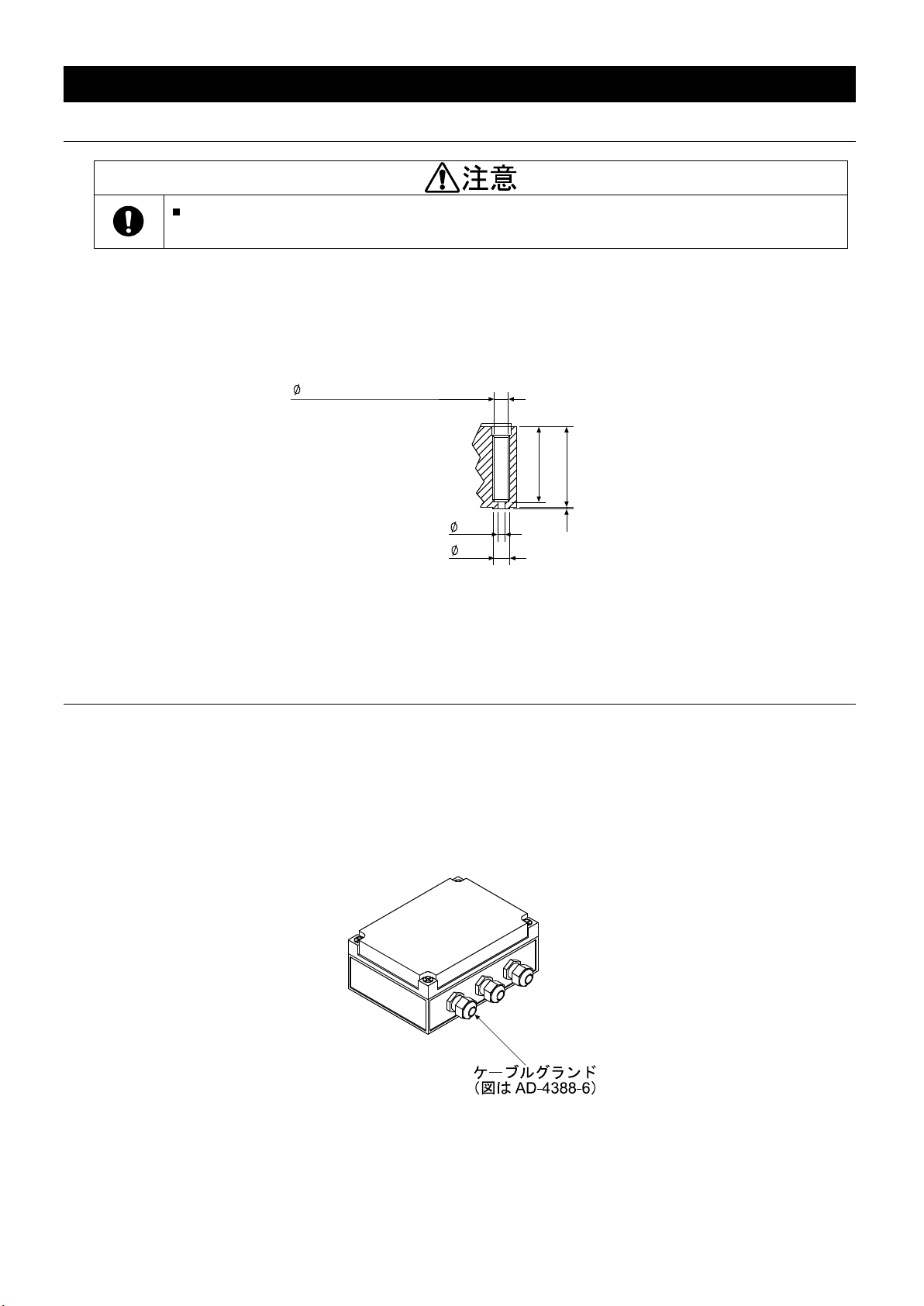
5-2 ケーブル挿入 ....................................................................................................................................................... 6
5-3 結線 ....................................................................................................................................................................... 7
5-4 ケーブルグランドの締め付け、フタの取り付け ............................................................................................ 7
6.調整....................................................................................................................................................................................... 8
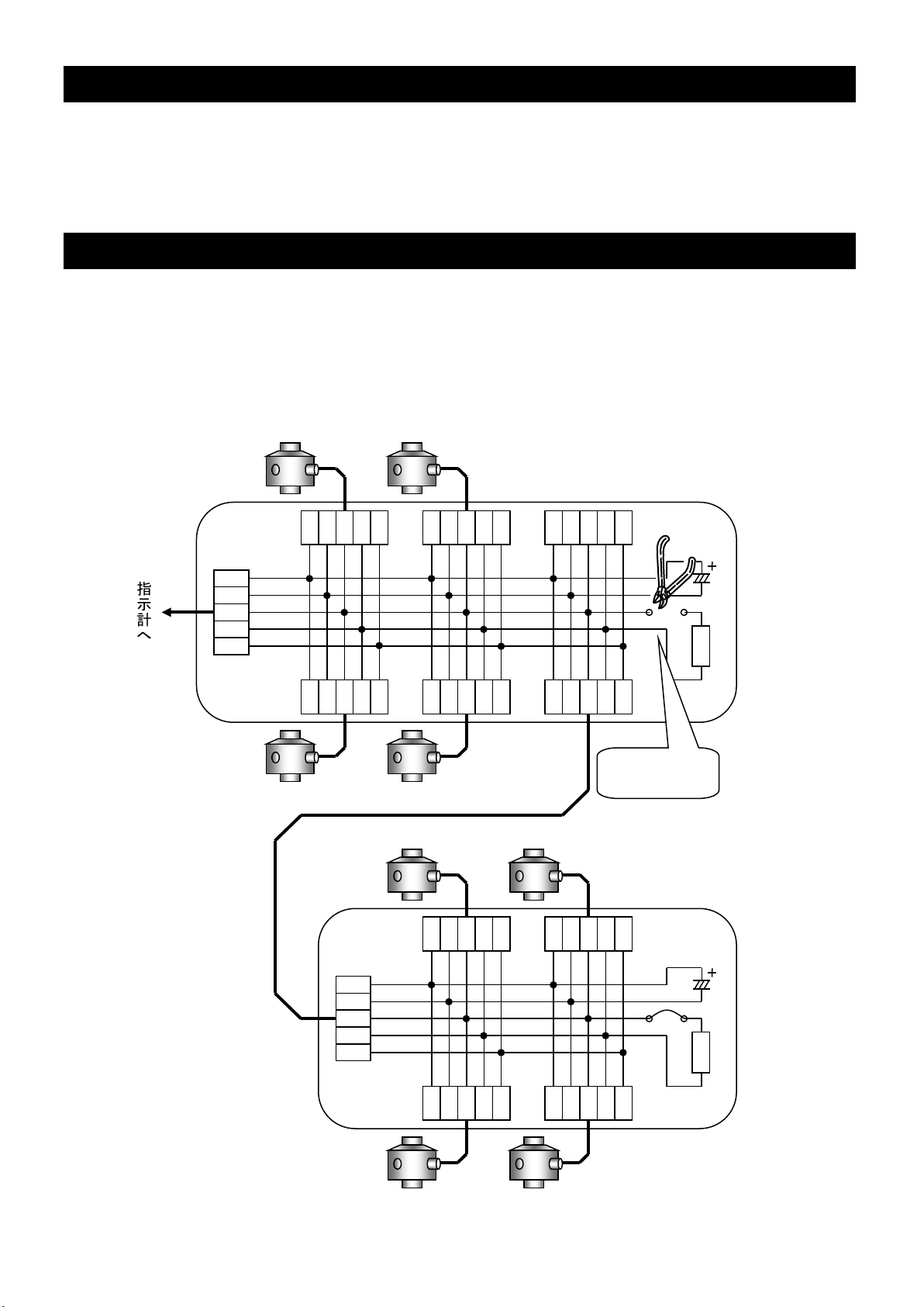
7.接続点数が6点を超える場合の接続方法 ........................................................................................................................ 8
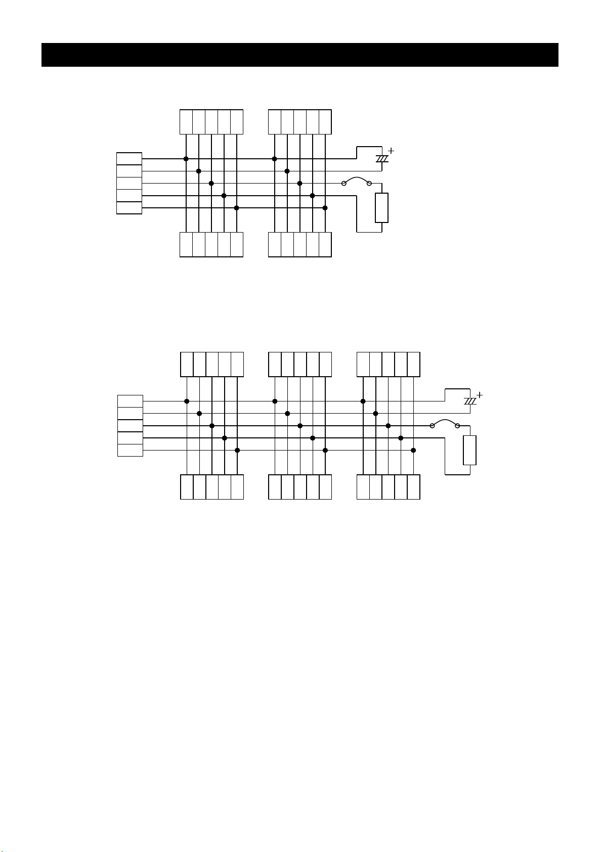
8.回路図 ................................................................................................................................................................................... 9
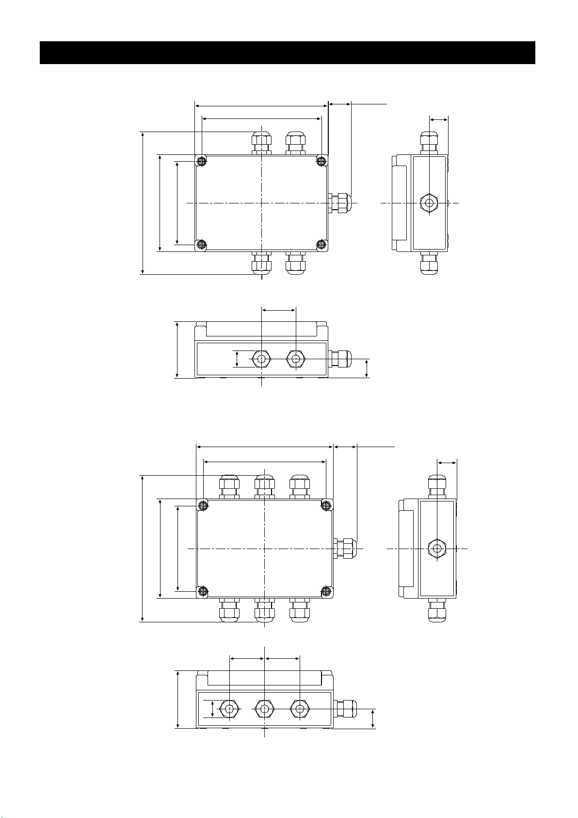
9.外形寸法図 ......................................................................................................................................................................... 10
CONTENTS
1. WARNING DEFINITIONS ....................................................................................................................................................11
2. PRECAUTIONS FOR USE..................................................................................................................................................11
3. INTRODUCTION.................................................................................................................................................................. 12
4. SPECIFICATIONS................................................................................................................................................................ 12
5. USING THE JUNCTION BOX ............................................................................................................................................ 13
5.1. Installing the junction box ...................................................................................................................................... 13
5.2. Inserting the cables ................................................................................................................................................ 13
5.3. Connecting the wires ............................................................................................................................................. 14
5.4. Tightening the cable glands and attaching the cover......................................................................................... 14
6. ADJUSTMENT...................................................................................................................................................................... 15
7. WHEN CONNECTING MORE THAN 6 LOAD CELLS................................................................................................... 15
8. CIRCUIT DIAGRAM............................................................................................................................................................. 16
9. EXTERNAL DIMENSIONS ................................................................................................................................................. 17

4
1.注意事項の表記方法
取扱説明書および製品には、誤った取り扱いによる事故を未然に防ぐため、次の警告サインと図記号を表示して
います。警告サインと図記号の意味は次の通りです。
警告サインの意味
この表記は、誤った取り扱いをすると、人が傷害を負ったり、物的損害の発生が想定
される内容を示します。
図記号の意味
記号は必ず守っていただきたいこと(強制)を示しています。具体的な強制内容は、
の中や近くに文書や絵で示します。左図の場合「守っていただきたいこと」を示します。
2.使用上(安全および危険防止)の注意事項
本製品を正しく安全にお使いいただくために、以下の注意事項をお守りください。
また、ご使用前に本書を必ずご一読ください。
弊社から納入後、設置までの間は水のかからないまた湿気の少ない場所に保管してください。
本器の設置場所には風雨および日光が直接当たらない場所を選んでください。また、長時
間にわたり水没するような場所への設置は避けてください。
本結線作業中は内部に水滴等が入らないよう注意してください。
シールドは必ず接続してください。接続されていない場合、動作が不安定になる可能性があ
ります。
ケーブルグランドはケーブルを通した後、確実に締め付けてください。締め付けがゆるい
と内部に浸水等を生じ故障の原因となります。
フタを取り付けるねじは確実に締め付けてください。締め付けがゆるいと内部に浸水等を
生じ故障の原因となります。

5
3.概要
AD-4388は、1台の指示計に複数のデジタルロードセルを接続して計量器を構成する時に使用する
接続箱です。
AD-4388-4では4個、AD-4388-6では6個のデジタルロードセルが接続可能です。
4.仕様
材質 本体:ポリエステル
ケーブルグランド:ポリアミド
許容温度範囲 -20℃~80℃
質量 AD-4388-4: 約0.51kg
AD-4388-6: 約0.56kg
保護等級 IP67相当
接続設定 接続点数 AD-4388-4: 4点
AD-4388-6: 6点
端子数 各入力 5端子/出力 5端子 ワンタッチ端子台使用
(使用可能電線 より線AWG24~16)
適合ケーブル径 φ5~φ10

6
5.使用方法
5-1 設置
本器の設置場所には風雨および日光が直接当たらない場所を選んでください。また、長時
間にわたり水没するような場所への設置は避けてください。
あらかじめ決めておいた設置場所にAD-4388を設置します。
フタ取付ねじ穴の底部に本体固定用のねじ穴があります。詳細寸法は図1を参照してください。
設置後は引き続き内部の結線作業ができるようにフタは外したままにしておきます。
単位:mm
図1 本体固定用ねじ穴 詳細寸法
5-2 ケーブル挿入
ケーブルを通すケーブルグランドはAD-4388-4で5箇所、AD-4388-6で7箇所あります。
全てのケーブルグランドにロードセルあるいは指示計からのケーブルを挿入します。
ケーブルグランドに空きが発生する場合は、防水性確保のためケーブルの代用となるものを挿入して穴をふ
さいでください。
図2 ケーブルグランド
45
8.3(フタ取付ねじ穴内径)
48
4.3
10
1

7
5-3 結線
本結線作業中は内部に水滴等が入らないよう注意してください。
シールドは必ず接続してください。接続されていない場合、動作が不安定になる可能性があ
ります。
端子台にケーブルを接続します。ねじなしのワンタッチ端子台を使用していますので、簡単にケーブルが
接続できます。ケーブルへの圧着端子取り付けは不要です。接続方法は図3を参照してください。
図3 端子台接続方法
ロードセルあるいは指示計からのケーブルを表1に従い接続してください。ケーブル色は弊社デジタルロ
ードセルのケーブル配線色に合わせています。
なお、ロードセルあるいは指示計を接続する端子台は特に決まっていません。それぞれ任意の端子台に接
続してください。
表1 端子配列とケーブル色
端子台(上面図)
No. 1 2 3 4 5
RED GRN YEL
POW+ DATA+ SHD
WHT BLU
POW - DATA -
No. 1 2 3 4 5
略号
RED
POW+
WHT
POW-
GRN
DATA+
BLU
DATA-
YEL
SHD
ケーブ
ル色
赤白緑青黄
接続 電源(+)電源(-)データ(+)データ(-)シールド
5-4 ケーブルグランドの締め付け、フタの取り付け
ケーブルグランドはケーブルを通した後、確実に締め付けてください。締め付けがゆるい
と内部に浸水等を生じ故障の原因となります。
フタを取り付けるねじは確実に締め付けてください。締め付けがゆるいと内部に浸水等を
生じ故障の原因となります。
接続が終わったら誤配線の有無を確認します。確認後、ケーブルグランドをしっかり締め付け、フタを取
り付けます。この際、それぞれのねじを確実に締め付けてください。締め付けがゆるいと内部に浸水等を
生じ故障の原因となります。
ケーブル挿入口

8
6.調整
特に接続箱で行う調整はありません。使用する指示計の取扱説明書に従って各種の設定、調整を行ってく
ださい。
7.接続点数が6点を超える場合の接続方法
接続点数が6点を超える場合は接続箱を複数個接続する必要があります。その場合、終端抵抗を整合する
ため、指示計から最も遠い側にある接続箱のジャンパ線(JP1)だけを残し、他の接続箱のジャンパ線
(JP1)はニッパ等で切断してください。
参考例としてAD-4388-4 とAD-4388-6を使用して8個のデジタルロードセルを接続す
る場合の結線図を図4に示します。
図4 8点接続での結線例
赤白緑青黄
100Ω
C1
R1
JP1
100Ω
C1
R1
JP1
赤
白
緑
青
黄
指示計へ
非接続
ジャンパ線
(JP1)
を
切断する
。
AD4388-6
AD-4388-4
赤白緑青黄
赤白緑青黄
赤白緑青黄
赤白緑青黄
赤白緑青黄
赤白緑青黄
赤白緑青黄
赤
白
緑
青
黄
赤白緑青黄
赤白緑青黄

9
8.回路図
AD-4388-4
AD-4388-6
図5 回路図
100
Ω
C1
R1
JP1
赤
白
緑
青
黄
赤
白
緑
青
黄
赤白緑青
黄
電源+ 赤
電源- 白
データ+
緑
データ-
青
シールド
緑
赤白緑青
黄
100
Ω
C1
R1
JP1
電源+ 赤
電源- 白
データ+
緑
データ-
青
シールド
緑
赤白緑青
黄
赤白緑青
黄
赤白緑青
黄
赤白緑青
黄
赤白緑青
黄
赤白緑青
黄

10
9.外形寸法図
AD-4388-4
AD-4388-6
単位:mm
図6 外形寸法図
175
45
157
MAX30
25
22
74
MAX 187
127
109
25
175
45
157
MAX30
25
22
74
MAX 187
127
109
25
45

11
1. WARNING DEFINITIONS
To prevent accidents due to inappropriate handling, this product and its manual contain the following
warning sign and symbol. The meanings of the warning sign and symbol are as follows.
Warning Definition
CAUTION
A potentially hazardous situation that may result in minor or moderate injury if not
avoided. This may also be used to alert about a situation that may cause damage
to property.
Symbol Definition
The symbol indicates a mandatory action. The mandatory action is described
inside or near the symbol, using text or a picture. The example indicates a general
mandatory action.
2. PRECAUTIONS FOR USE
In order to use the junction box safely and correctly, carefully read the following precautions and be sure to
observe them. In addition, read the instruction manual thoroughly before using the junction box.
CAUTION
Upon receipt and before installation, store the junction box where it will not get wet and
where humidity is low.
Install the junction box where it is not directly exposed to rain, wind, or sunshine. Avoid
locations where the junction box may be immersed in water for a long period of time.
During wiring operations, use care so that water will not enter the box interior.
Make sure the cable shield is grounded. Otherwise, the box performance will be unstable
and readings may not be accurate.
After the cable is connected, tighten the cable gland firmly. Insufficient tightening will allow
water to enter the box interior and result in a malfunction.
Tighten the screws to secure the cover firmly. Insufficient tightening will allow water to
enter the box interior and result in a malfunction.

12
3. INTRODUCTION
The AD-4388 series junction box is used to form a weighing system when multiple digital load cells are
connected to a weighing indicator.
AD-4388-4: Four digital load cells can be connected.
AD-4388-6: Six digital load cells can be connected.
4. SPECIFICATIONS
Material Main unit: polyester
Cable gland: polyamide
Permissible temperature range -20 °C to 80 °C
Mass AD-4388-4: approx. 0.51 kg
AD-4388-6: approx. 0.56 kg
IP rating IP67
Number of load cells to be connected AD-4388-4: 4
AD-4388-6: 6
Number of terminals Input: 5 / Output: 5 Spring clamp terminals used
(Usable wire: AWG 24 to AWG 16 twisted wire)
Applicable cable diameter 5 mm to 10 mm

13
5. USING THE JUNCTION BOX
5.1. Installing the junction box
CAUTION
Install the junction box where it is not directly exposed to rain, wind, or sunshine. Avoid
locations where the junction box may be immersed in water for a long period of time.
Install the junction box in a predetermined installation site.
A screw hole to secure the junction box is located at the bottom of the cover securing screw hole.
For detailed sizes, refer to Fig. 1.
After installation, keep the cover removed for internal wiring operations.
Unit: mm
Fig. 1 Detailed view of the screw hole to secure the junction box
5.2. Inserting the cables
The AD-4388-4 has five and the AD-4388-6 has seven cable glands to pass cables through. All the cable
glands for each model must have a cable from a load cell or a weighing indicator inserted.
If some cable glands are left vacant, insert asubstitute object in place of a cable to seal the glands to ensure
watertight performance.
Fig.2 Cable glands

14
5.3. Connecting the wires
CAUTION
During wiring operations, use care so that water will not enter the box interior.
Make sure the cable shield is grounded. Otherwise, the box performance will be unstable
and readings may not be accurate.
Connect the wires to the terminal block. As the terminal block is a spring clamp type, connecting wires is
simple and no compression lug is required. For the wiring procedure, refer to Fig.3
Fig.3 Terminal wiring procedure
Connect the wire from the load cell or a weighing indicator according to Table 1. The wire color matches the
wiring color of A&D digital load cell.
No particular terminal block is assigned to connect load cells or a weighing indicator. Use any terminal
block.
Table 1 Terminal assignment and wire color
Terminal (Top view)
No. 1 2 3 4 5
RED GRN YEL
POW+ DATA+ SHD
WHT BLU
POW - DATA -
No. 1 2 3 4 5
Symbol RED
POW+
WHT
POW-
GRN
DATA+
BLU
DATA-
YEL
SHD
Wire Color Red (R) White(W) Green(G) Blue (B) Yellow(Y)
Connection Power
supply(+)
Power
supply(-) Data ( + ) Data ( - ) Shield
5.4. Tightening the cable glands and attaching the cover
CAUTION
After the cables are connected, tighten the cable glands firmly. Insufficient tightening will
allow water to enter the box interior and result in a malfunction.
Tighten the screws to secure the cover firmly. Insufficient tightening will allow water to
enter the box interior and result in a malfunction.
When wiring operations are complete, check each connection to make sure it is correct. Then, tighten the
cable glands firmly and attach the cover securely by tightening the screws firmly. Insufficient tightening will
allow water to enter the box interior and result in a malfunction.
Wire insert port

15
6. ADJUSTMENT
No adjustment is required to the junction box. Refer to the manual of the weighing indicator used to perform
various settings and adjustments.
7.
WHEN CONNECTING MORE THAN 6 LOAD CELLS
When connecting more than six load cells, multiple junction boxes are required.
In that case, to have a termination resistance of 100 Ω, do the following.
Leave the jumper (JP1) in the junction box installed furthermost from the weighing indicator as is and cut
the jumpers (JP1) in the other junction boxes, using nippers.
Fig.4 shown below is an example connection diagram, using an AD-4388-4 and an AD-4388-6 to connect
eight digital load cells.
Fig.4 Connection example using eight load cells
R W GBY
100
Ω
C1
R1
JP1
100
Ω
C1
R1
JP1
R
W
G
B
Y
To weighing indicator
No connection
Cut the jumper
(
JP1).
AD-4388-6
AD-4388-4
R W GBY
R W GBY
RWGBY
R W GBY
R W GBY
R W GBY
R W GBY
R
W
G
B
Y
R W GBY
R W GBY

16
8. CIRCUIT DIAGRAM
AD-4388-4
AD-4388-6
Fig.5 Circuit diagram
Power supply +
Power supply
-
Data +
Data
-
Shield
100
Ω
C1
R1
JP1
RWGBY
RWGBY
RWGBY
RWGBY
R
W
G
B
Y
100
Ω
C1
R1
JP1
RWGBY
RWGBY
RWGBY
RWGBY
RWGBY
RWGBY
Power supply +
Power supply
-
Data +
Data
-
Shield
R
W
G
B
Y

17
9. EXTERNAL DIMENSIONS
AD-4388-4
AD-4388-5
Unit: mm
Fig.6 External dimensions
175
45
157
MAX30
25
22
74
MAX 187
127
109
25
175
45
157
MAX 30
25
22
74
MAX 187
127
109
25
45

18
MEMO

A&D Company, Limited
3-23-14 Higashi-Ikebukuro, Toshima-ku, Tokyo 170-0013, JAPAN
Telephone: [81] (3) 5391-6132 Fax: [81] (3) 5391-1566
A&D ENGINEERING, INC.
1756 Automation Parkway, San Jose, California 95131, U.S.A.
Telephone: [1] (408) 263-5333 Fax: [1] (408)263-0119
A&D INSTRUMENTS LIMITED
Unit 24/26 Blacklands Way, Abingdon Business Park, Abingdon, Oxfordshire OX14 1DY United Kingdom
Telephone: [44] (1235) 550420 Fax: [44] (1235) 550485
A&D AUSTRALASIA PTY LTD
32 Dew Street, Thebarton, South Australia 5031, AUSTRALIA
Telephone: [61] (8) 8301-8100 Fax: [61] (8) 8352-7409
A&D KOREA Limited 한국에이.엔.디(주)
서울특별시 영등포구 국제금융로6길33 (여의도동) 맨하탄빌딩 817 우편 번호 07331
( 817, Manhattan Bldg., 33. Gukjegeumyung-ro 6-gil, Yeongdeungpo-gu, Seoul, 07331 Korea )
전화: [82] (2) 780-4101 팩스: [82] (2) 782-4264
OOO A&D RUS OOO "ЭЙ энд ДИ РУС"
Почтовый адрес:121357, Российская Федерация, г.Москва, ул. Верейская, дом 17
Юридический адрес: 117545, Российская Федерация, г. Москва, ул. Дорожная, д.3, корп.6, комн. 8б
( 121357, Russian Federation, Moscow, Vereyskaya Street 17 )
тел.: [7] (495) 937-33-44 факс: [7] (495) 937-55-66
A&D Instruments India Private Limited
( 509, Udyog Vihar, Phase-, Gurgaon - 122016, Haryana, India )
: [91] (124) 4715555 : [91] (124) 4715599
A&D SCIENTECH TAIWAN LIMITED. A&D台灣分公司 艾安得股份有限公司
台湾台北市中正區青島東路 5 號 4 樓
( 4F No.5 Ching Tao East Road, Taipei Taiwan R.O.C. )
Tel : [886](02) 2322-4722 Fax : [886](02) 2392-1794
A&D INSTRUMENTS (THAILAND) LIMITED บริษัท เอ แอนด ดี อินสทรูเมนท (ไทยแลนด) จํากัด
168/16 หมูที่ 1 ตําบลรังสิต อําเภอธัญบุรี จังหวัดปทุมธานี 12110 ประเทศไทย
( 168/16 Moo 1, Rangsit, Thanyaburi, Pathumthani 12110 Thailand )
Tel : [66] 20038911

This manual suits for next models
2
Table of contents
Popular Safety Equipment manuals by other brands

FALL SAFE
FALL SAFE INSPECTOR FS874 instruction manual

Clevertronics
Clevertronics L10 Jumbo LJELED-40 Series Installation & maintenance instructions

ultraMEDIC
ultraMEDIC ultraHEAD-LOCK II operating manual

3M
3M DFS 700 Installation and user manual

COURANT
COURANT Autoroll quick start guide

3M
3M DBI-SALA Nano-Lok XL instruction manual