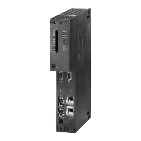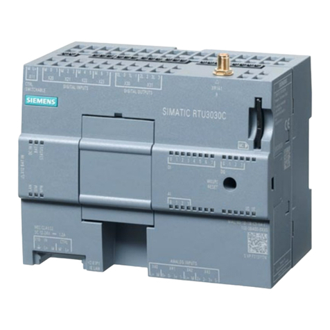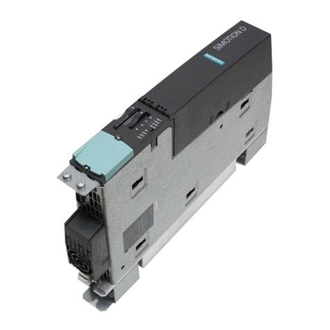
Analog input module AI 4xTC HS (6ES7134-6JD00-0DA1)
Manual, 03/2019, A5E42405270-AB 5
Preface ................................................................................................................................................... 3
1 Guide to documentation .......................................................................................................................... 6
2 Product overview .................................................................................................................................. 10
2.1 Properties................................................................................................................................10
2.2 Spare part compatibility ..........................................................................................................12
3 Wiring ................................................................................................................................................... 13
3.1 Wiring and block diagram .......................................................................................................13
4 Parameters/address space ................................................................................................................... 15
4.1 Measurement types and measuring ranges ...........................................................................15
4.2 Parameters .............................................................................................................................15
4.3 Explanation of parameters ......................................................................................................19
4.4 Scalable measuring range ......................................................................................................23
4.4.1 Configuration...........................................................................................................................25
4.4.2 Evaluate status and limits of scalable measuring range.........................................................26
4.5 REAL representation...............................................................................................................28
4.6 Address space ........................................................................................................................29
5 Interrupts/diagnostics alarms................................................................................................................. 37
5.1 Status and error display ..........................................................................................................37
5.2 Interrupts.................................................................................................................................39
5.3 Diagnostics alarms..................................................................................................................40
6 Technical specifications ........................................................................................................................ 42
A Parameter data records......................................................................................................................... 49
A.1 Dependencies when configuring with GSD file.......................................................................49
A.2 Parameter assignment and structure of the parameter data record (S7 representation).......51
A.3 Parameter assignment and structure of channel parameter (REAL representation) .............59
B Representation of analog values ........................................................................................................... 67
B.1 Representation of input ranges...............................................................................................68
B.2 Representation of analog values in voltage measuring ranges..............................................68
B.3 Representation of analog values for thermocouples ..............................................................69
