ABB 4690 Series User manual

—
ABB MEASUREMENT & ANALYTICS | OPERATING INSTRUCTION | OI/ATS410-EN REV. A
4690 Series
Turbidity sensor
Accurate, reliable turbidity
measurement
Measurement made easy
Introduction
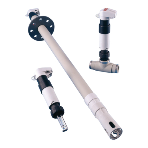
The 4690 sensor is a rugged, reliable instrument
designed to measure the turbidity content of water.
The sensor also has additional features including
dry standard verification and automatic cleaning.
The sensor is designed for use with the ABB AWT420
dual-input transmitter.
For more information
Publications for the associated transmitters are
available for free download from:
www.abb.com/measurement
or by scanning this code:
Search for or click on:
Data Sheet
AWT420
Universal 4-wire, dual-input transmitter
DS/AWT420 - EN
Data Sheet
4690 Series
Turbidity Sensor
DS/ATS410-EN
Operating Instruction
AWT420
Universal 4-wire, dual-input transmitter
OI/AW T420 -EN
—
4690 turbidity sensor

24690 SERIES | TURBIDITY SENSOR | OI/ATS410-EN REV. A
Sales Service Software
Contents
1 Health and safety . . . . . . . . . . . . . . . . . . . . . . . . . . . . . . . 3
Safety precautions . . . . . . . . . . . . . . . . . . . . . . . . . . . . . . . . . . . . 3
Potential safety hazards . . . . . . . . . . . . . . . . . . . . . . . . . . . . . . . . 3
Electrical safety. . . . . . . . . . . . . . . . . . . . . . . . . . . . . . . . . . . . . . 3
Product symbols . . . . . . . . . . . . . . . . . . . . . . . . . . . . . . . . . . . . . 4
End-of-life battery disposal.......................................... 4
Information on RoHS Directive 2011/65/EU (RoHS II) . . . . . . . . . . . . . . 4
2 Turbidity sensor components . . . . . . . . . . . . . . . . . . . . . . . 5
3 Installation . . . . . . . . . . . . . . . . . . . . . . . . . . . . . . . . . . . 6
Siting requirements . . . . . . . . . . . . . . . . . . . . . . . . . . . . . . . . . . . 6
Install the turbidity sensor . . . . . . . . . . . . . . . . . . . . . . . . . . . . . . . 6
Sample flow rate .....................................................7
Install the optional de-bubbler . . . . . . . . . . . . . . . . . . . . . . . . . . . . 8
Mounting the de-bubbler ............................................ 8
Setup procedure for the de-bubbler .................................. 9
4 Turbidity sensor electrical connections . . . . . . . . . . . . . . . . 10
5 Calibration . . . . . . . . . . . . . . . . . . . . . . . . . . . . . . . . . . 11
Care and maintenance of secondary standards . . . . . . . . . . . . . . . . . . 11
Calibration verification with a secondary standard . . . . . . . . . . . . . . .12
Calibration with a primary standard . . . . . . . . . . . . . . . . . . . . . . . . . 13
6 Maintenance . . . . . . . . . . . . . . . . . . . . . . . . . . . . . . . . . 14
Cleaning the sensors without a wiper unit . . . . . . . . . . . . . . . . . . . . . 14
Cleaning the sensors with a wiper unit . . . . . . . . . . . . . . . . . . . . . . .14
7 Fault finding . . . . . . . . . . . . . . . . . . . . . . . . . . . . . . . . . 14
Unstable or erratic readings . . . . . . . . . . . . . . . . . . . . . . . . . . . . . . 14
Intermittent short-term spikes in turbidity readings. . . . . . . . . . . . . . . 14
8 Specifications . . . . . . . . . . . . . . . . . . . . . . . . . . . . . . . . 15
9 Spares and consumables . . . . . . . . . . . . . . . . . . . . . . . . . 16
Maintenance kits . . . . . . . . . . . . . . . . . . . . . . . . . . . . . . . . . . . . . 16
Accessories . . . . . . . . . . . . . . . . . . . . . . . . . . . . . . . . . . . . . . . .16
Upgrade kits. . . . . . . . . . . . . . . . . . . . . . . . . . . . . . . . . . . . . . . . 16
Strategic spares . . . . . . . . . . . . . . . . . . . . . . . . . . . . . . . . . . . . .16
De-bubbler. . . . . . . . . . . . . . . . . . . . . . . . . . . . . . . . . . . . . . . . . 16

4690 SERIES | TURBIDITY SENSOR | OI/ATS410-EN REV. A 3
1 Health and safety
Symbols that appear in this document are explained below:
WARNING
The signal word ‘WARNING’ indicates an imminent danger.
Failure to observe this information may result in death or
severe injury.
CAUTION
The signal word ‘CAUTION’ indicates an imminent danger.
Failure to observe this information may result in minor or
moderate injury.
NOTICE
The signal word ‘NOTICE’ indicates potential material
damage.
Note
‘Note’ indicates useful or important information about the
product.
Safety precautions
Be sure to read, understand and follow the instructions
contained within this manual before and during use of the
equipment. Failure to do so could result in bodily harm or
damage to the equipment.
Potential safety hazards
4690 turbidity sensor – electrical damage to the equipment.
WARNING
Bodily injury.
To ensure safe use when operating this equipment, the
following points must be observed:
• Normal safety precautions must be taken to avoid the
possibility of an accident occurring when operating in
conditions of high pressure and/or temperature.
Safety advice concerning the use of the equipment
described in this manual or any relevant Material Safety
Data Sheets (where applicable) can be obtained from the
Company, together with servicing and spares information.
Electrical safety
This equipment complies with the requirements of CEI/IEC
61010-1 Edition 3.1 2017-01 ‘Safety Requirements for Electrical
Equipment for Measurement, Control and Laboratory Use’ and
complies with US NEC 500, NIST and OSHA.
If the equipment is used in a manner that is not specified by the
Company, the protection provided by the equipment may be
impaired.

44690 SERIES | TURBIDITY SENSOR | OI/ATS410-EN REV. A
Product symbols
Symbols that may appear on this product are shown below:
Protective earth (ground) terminal.
Functional earth (ground) terminal.
This symbol, when noted on a product, indicates a
potential hazard which could cause serious personal
injury and/or death. The user should reference this
instruction manual for operation and/or safety
information.
This symbol, when noted on a product enclosure or
barrier, indicates that a risk of electrical shock and/or
electrocution exists and indicates that only
individuals qualified to work with hazardous voltages
should open the enclosure or remove the barrier.
Recycle separately from general waste under the
WEEE directive.
Direct current supply only.
Alternating current supply only.
Both direct and alternating current supply.
The equipment is protected through double
insulation.
Product recycling and disposal
(Europe only)
ABB is committed to ensuring that the risk of any
environmental damage or pollution caused by any of
its products is minimized as far as possible. The
European Waste Electrical and Electronic Equipment
(WEEE) Directive that initially came into force on
August 13 2005 aims to reduce the waste arising from
electrical and electronic equipment; and improve the
environmental performance of all those involved in
the life cycle of electrical and electronic equipment.
In conformity with European local and national
regulations, electrical equipment marked with the
above symbol may not be disposed of in European
public disposal systems after 12 August 2005.
NOTICE
For return for recycling, please contact the equipment
manufacturer or supplier for instructions on how to return
end-of-life equipment for proper disposal.
End-of-life battery disposal
The transmitter contains a small lithium battery (located on the
processor/display board) that must be removed and disposed
of responsibly in accordance with local environmental
regulations.
Information on RoHS Directive 2011/65/EU
(RoHS II)
ABB, Industrial Automation, Measurement &
Analytics, UK, fully supports the objectives of the
RoHS II directive. All in-scope products placed on the
market by IAMA UK on and following the 22nd of July
2017 and without any specific exemption, will be
compliant to the RoHS II directive, 2011/65/EU.
4690 SERIES | TURBIDITY SENSOR | OI/ATS410-EN REV. A 5
2 Turbidity sensor components
Sample outlet
Flow chamber
Inlet/isolating
valve Drain valve
Optical receiver
Optical emitter
Wiper unit
Flow
chamber
Sample outlet Wiper plug
Optical emitter
Optical
receiver
Drain valve
Inlet/isolating
valve
Figure 1 Primary components of the turbidity sensor

64690 SERIES | TURBIDITY SENSOR | OI/ATS410-EN REV. A
3 Installation
Siting requirements
Make sure that there is a clearance of 200 mm (7.9 in) all around the sensor, to let the turbidity sensor be easily removed for
maintenance. Refer to Install the turbidity sensor for the dimensions of the sensor.
Install the sensor at a height that gives easy access during calibration and cleaning.
NOTICE
Do not install the sensor in direct sunlight.
Install the turbidity sensor
Figure 1 identifies the main components of each sensor.
Referring to Figure 2 or Figure 3:
1 Install the sensor in the position shown with the brackets that are provided. Make sure that the sensor is installed within 5° of
its vertical axis.
2 Connect the sample inlet tube and the sample drain tube.
3 Connect the sample outlet tube. Refer to Figure 4.
Dimensions in mm (in)
298.0 (11.7)
155.5 (6.12)46.5
(1.83)
Sample inlet connector
(12 [0.5] ID tube)
Sample drain connector
(12 [0.5] ID tube)
230.0 (9.0)
403.0
(17.0)
see
Note
below
6 x Ø7 (0.3)
Mounting holes
118.0
(4.65)
Figure 2 Sensor dimensions (with the optional wiper unit)
Note.
Leave an additional clearance of approximately 30 mm (1.2 in) above the wiper unit for the bend in the wiper unit cable.

4690 SERIES | TURBIDITY SENSOR | OI/ATS410-EN REV. A 7
Dimensions in mm (in)
298.0 (11.7)
155.5 (6.12)46.5
(1.83)
Sample inlet connector
(12 [0.5] ID tube)
Sample drain connector
(12 [0.5] ID tube)
230.0 (9.0)
282.0
(11.1)
6 × Ø7 (0.3)
Mounting holes
118.0
(4.65)
Figure 3 Sensor dimensions (without the optional wiper unit)
Sample flow rate
Set a minimum flow rate of 0.5 L/min to prevent solids settling
in the pipework. Increase the flow rate if it is necessary, but do
not exceed the maximum flow rate of 1.5 L/min.
When measuring turbidity, it is important to eliminate
additional sources of light scattering, such as gas bubbles in
the sample. An optional de-bubbler (part number 7997 500) is
available to eliminate gas bubbles. Refer to Install the optional
de-bubbler on page 8.
Sample outlet
connector (6 [0.25] ID
tube)
Figure 4 4690 Series – sample outlet connector location

84690 SERIES | TURBIDITY SENSOR | OI/ATS410-EN REV. A
Install the optional de-bubbler
Mounting the de-bubbler
Mount the de-bubbler vertically with the flow upwards.
Disconnect fittings – 12 (0.5) ID
tube (rotatable through 360°)
Drain outlet
Sample outlet
Removable fitting
12 (0.5) ID tubing
150
(5.9)
CRS
Ø6.5
(0.25)
540
(21.3)
88
(3.5)
91
(3.6)
Sample inlet
Figure 5 De-bubbler mounting information
(de-bubbler part number 7997 500)

4690 SERIES | TURBIDITY SENSOR | OI/ATS410-EN REV. A 9
Setup procedure for the de-bubbler
For systems that include a de-bubbler, refer to Figure 6:
1 Open the ‘sample in’ isolating valve Ato keep the overflow from the de-bubbler at a minimum.
2 Adjust the sample flow through the turbidity system with the flow regulating valve B.
Note.
It is recommended to use the sample regulating valves together with a flow indicator to ensure easy maintenance and consistent
performance. These devices are not supplied with the 4690 Turbidity systems.
Figure 6 Typical system installation for 4690 series turbidity systems
NOTICE
1 To prevent degassing of the sample, which can cause very erratic readings, do not exceed this measurement.
2 This is the minimum installation distance that ensures adequate flow rate through the sensor. Increase this distance if you
use long tubing or small-bore tubing.
Dimensions in mm (in)
A
B
De-bubbler
Drain outlet
500 (19.7) minimum
– see Notice 2
Sample in
Drain valve
Optional
150 (5.9) maximum
– see Notice 1
Inlet/isolating
valve
Tundish
150 (5.9) maximum
– see Notice 1
4690 series
Sample outlet
connector
Tundish

10 4690 SERIES | TURBIDITY SENSOR | OI/ATS410-EN REV. A
4 Turbidity sensor electrical connections
Link
To
AWT420
transmitter
Green
Red
Blue
Yellow
Blue
Screen
Red
Emitter
Blue
Green
Red
Screen
Receiver
Blue
Red
Screen
Green
Yellow
Wiper unit
(optional)
Screen
White
Black
Figure 7 Turbidity sensor junction box connections

4690 SERIES | TURBIDITY SENSOR | OI/ATS410-EN REV. A 11
5 Calibration
A key feature of the 4690 Series Turbidity system is the dry
secondary calibration standard. This is designed to simplify
routine calibration verification and minimizes the need for
chemical standards.
Each dry calibration standard is verified against a primary
formazine standard before delivery, and the nominal turbidity
value is indicated on the label.
For regulatory monitoring, use the secondary calibration
standard for monthly calibration verification and periodically
monitor it for deterioration using a primary standard.
Definitions
• Primary standards
Turbidity standards that are traceable and equivalent to
the reference turbidity standard, within statistical errors.
Formazine is the most commonly acceptable form of
primary standard. The other is a commercially
manufactured liquid suspension of styrene divinylbenzene
polymer beads (SDB). Primary standards are used to
calibrate a turbidity analyzer directly or to calibrate a
secondary standard.
• Secondary standards
Standards that the manufacturer (or an independent
testing organization) has certified give analyzer
calibration results equivalent (within certain limits) to the
results obtained when the analyzer is calibrated with a
primary standard.
• Calibration
A procedure that checks or adjusts an analyzer’s accuracy
by comparison with a defined standard or reference.
• Calibration verification
A procedure used to check whether or not the calibration
of the analyzer is within certain limits.
Care and maintenance of secondary
standards
ABB’s secondary standards may be used repeatedly but must
be monitored for deterioration.
All secondary standards can change gradually with time.
Deterioration can be detected by measuring the turbidity value
of the secondary standard after calibration of the analyzer with
a primary calibration standard.
It is recommended that secondary standards are checked every
three months against a primary standard on the analyzer they
are intended to be used with.
If the comparison with a primary standard shows that the
turbidity value of the secondary standard has changed, the
secondary standard can be assigned a new turbidity value for
use in future calibration verification.
Included with each sensor is a calibration record card kit for
recording the value of the secondary standard compared to the
primary calibration data for each individual analyzer with which
the secondary standard is used.
Additional calibration record card kits can be purchased from
ABB (part no. 7998190 for pack of 3).
Turbidity Monitor Primary Calibration Card
Sensor Serial Number:
Dry Standard Serial Number:
Time/Date of Primary
Calibration
Dry Standard
Reading after
Primary Calibration
(NTU)
Performed By
Reorder Code: 7998190
Issue A, 08/06/2011 ABB Limited, Oldends Lane, Stonehouse, GL10 3TA
Time/Date of Primary
Calibration
Dry Standard
Reading after
Primary Calibration
(NTU)
Performed By
Figure 8 Example of calibration record card
To minimize deterioration of the secondary standard:
• Carefully clean any residual moisture after use.
• Clean the prism with a cloth that has no lint.
• Do not touch the dry standard rod. Fingerprints on the
surface can have an effect on its stated value.
• Keep it in the container provided when not in use, and keep
it in a dry place.

12 4690 SERIES | TURBIDITY SENSOR | OI/ATS410-EN REV. A
Calibration verification with a secondary
standard
To check the calibration:
1 Close the isolating valve that is installed upstream of the
sensor.
2 Close the sensor inlet valve.
3 Open the drain valve. Let the sensor drain.
NOTICE
When you remove the wiper unit, do not put too much force
on the wiper because it can bend the wiper arm out of 90°.
When you remove the wiper, make sure that the wiper arm is
not bent.
4 Carefully remove the wiper unit (7998 011 and 012) or the
wiper plug (7998 016 and 017) to aid complete drainage of
the system.
5 When the system is empty, close the drain valve.
6 Thoroughly dry the flow chamber internally using clean
tissue.
7 Thoroughly clean and dry the emitter and receiver lenses
using clean tissue.
8 If there is condensation on the emitter and receiver lenses:
a Leave the sensor open to let the lenses reach ambient
temperature before you do the calibration.
9 Insert the dry calibration standard with the zero NTU
indication (see Figure 9 or Figure 10) facing the optical
receiver, ensuring the locating lug engages correctly. Refer
to Figure 11.
10 Note the reading on the display.
11 Remove the dry standard, turn it through 180° and refit it,
ensuring that the NTU value indication (refer to Figure 9 or
Figure 10) faces the receiver and the locating lug engages
correctly. Refer to Figure 11.
12 Note the reading on the display.
13 If the readings noted at steps 9 and 10 exceed ±5 % of dry
standard value:
a Repeat the procedure from step 7.
b If the readings are still outside this range, calibrate the
sensor.
14 Remove the dry standard and put it in its storage container.
15 Refit the wiper unit (7998 011 and 012) or wiper plug
(7998 016 and 017).
16 Open the inlet valve and ensure that the flow through the
sensor is 0.5 to 1.5 L/min–1.
N
U
S
T
A
N
D
.
N
U
NTU value indication Zero NTU indication
Figure 9 Dry calibration standard for low range sensors
S
T
A
N
D
.
N
U
S
T
A
N
D
.
N
U
NTU value indication Zero NTU indication
Figure 10 Dry calibration standard for high range sensors
NTU value
indication
Zero NTU
indication
Locating lug
Optical
emitter
Optical
receiver
Figure 11 Inserting dry standard

4690 SERIES | TURBIDITY SENSOR | OI/ATS410-EN REV. A 13
Calibration with a primary standard
Before you do a wet standard calibration, make sure that a
stock formazine solution is available. If a stock solution is not
available, 24 hours must elapse before a freshly prepared
solution can be used.
To prepare the sensor assembly for wet (Formazine)
calibration:
1 Close the isolating valve installed upstream of the sensor.
2 Close the sensor inlet valve.
3 Open the drain valve. Let the sensor drain.
NOTICE
When you remove the wiper unit, do not put too much force
on the wiper because it can bend the wiper arm out of 90°.
When you remove the wiper, make sure that the wiper arm is
not bent.
4 Carefully remove the wiper unit (7998 011 and 012) or the
wiper plug (7998 016 and 017) to aid complete drainage of
the system.
5 When the system is empty, close the drain valve.
6 Thoroughly dry the flow chamber internally using clean
tissue.
7 Thoroughly clean and dry the emitter and receiver lenses
using clean tissue.
8 If there is condensation on the emitter and receiver lenses:
a Leave the sensor open to let the lenses reach ambient
temperature before you do the calibration.
9 Insert the dry calibration standard with the zero NTU
indication (refer to Figure 12 or Figure 13) facing the optical
receiver, ensuring the locating lug engages correctly. Refer
to Figure 14.
NOTICE
Do not touch the light-reflecting parts of the standard.
N
U
S
T
A
N
D
.
N
U
NTU value indication Zero NTU indication
Figure 12 Dry calibration standard for low range sensors
S
T
A
N
D
.
N
U
S
T
A
N
D
.
N
U
NTU value indication Zero NTU indication
Figure 13 Dry calibration standard for high range sensors
NTU value
indication
Zero NTU
indication
Locating lug
Optical
emitter
Optical
receiver
Figure 14 Inserting dry standard

14 4690 SERIES | TURBIDITY SENSOR | OI/ATS410-EN REV. A
6 Maintenance
The servicing schedule in Table 1 is a guide only. Because the
turbidity systems are designed for a wide range of
applications, and the nature of the sample can vary
considerably, it might be necessary to change the schedule to
apply to the particular installation and sample conditions.
Task Recommended frequency
Wiper blade replacement Quarterly
LED light source (ISO 7027) replacement kit Every 5 years
Table 1 Suggested maintenance schedule
Cleaning the sensors without a wiper unit
These sensors are normally used on clean water samples. Under
normal conditions, they may only require manual monthly
cleaning of the flow chamber.
However, if a high turbidity breakthrough occurs, clean the flow
chamber immediately to make sure that the readings are
accurate.
Cleaning the sensors with a wiper unit
The required automatic cleaning frequency of the flow chamber
and optical windows of the sensors can be determined only by
plant experience.
It is recommended to do checks at appropriate intervals.
7 Fault-finding
Unstable or erratic readings
There are a number of possible causes of unstable or erratic
readings. Look for air bubbles in the sample. The bubbles might
be due to degassing of the sample, caused by either a drop in
sample pressure, or a rise in temperature.
Frequent cleaning of the optical windows helps prevent the
accumulation of bubbles. If you see bubbles, it is recommended
to install the optional de-bubbler unit. Refer to Install the
optional de-bubbler on page 8.
Where the noise level gradually worsens over time, this usually
indicates that solids accumulated in the flow cell. An increase in
the flow rate through the flow cell might reduce this build up.
The flow cell must be cleaned manually.
Intermittent short-term spikes in turbidity
readings
This is usually caused by bubbles that go through the light path
in the flow cell. The bubbles are a result of degassing.
Degassing is not an instantaneous process, and it is possible
that it occurs after the sample has gone through the
de-bubbler. The bubbles start to form in the sample pipework
and the flow cell. As the bubbles grow gradually, the bubbles
finally release and flow through the light path. This causes a
spike in the turbidity reading.
The analyzer can be programmed for bubble rejection to
remove short-term spikes from the readings. For optimum
operation, operate the wiper unit frequently to prevent bubbles
accumulating on the windows.

4690 SERIES | TURBIDITY SENSOR | OI/ATS410-EN REV. A 15
8 Specifications
Sensor
Range
Low range 0 to 40 NTU
High range 0 to 400 NTU
Measurement principle
90° scattered light measurement
Compliant to ISO 7027
Maximum linearity
Typically <1.0 %
Accuracy1, 2
Low range version ±2 % of reading
High range version ±5 % of reading or 0.3 NTU
Repeatability3
0 to 200 NTU <1 %
200 to 400 NTU 2 %
Limit of Detection4
Low range version: 0.003 NTU
High range version: 0.3 NTU
Response time
T90 < 1 min at 1 L/min
Flow rate
0.5 to 1.5 L/min (0.13 to 0.39 galUS/min)
Integral wiper cleaning system
Programmable operational frequency every 0.25 h, 0.5 h,
0.75 h or multiples of 1 h up to 24 h
Sample operating temperature
0 to 50 °C (32 to 122 °F)
Sample pressure
Up to 3 bar (43.5 psi)
Ambient operating temperature
0 to 50 °C (32 to 122 °F)
Ambient operating humidity
Up to 95 % RH
1 Maximum measured error across full measurement range (limited by
uncertainty in Formazine standards).
2 Tested in accordance with IEC 61298 Parts 1-4: Edition 2.0 2008-10.
3 Tested in accordance with MCERTS: Performance Standards and Test
Procedures for Continuous Water Monitoring Equipment. Version 3.1:
Environment Agency 2010.
4 Tested in accordance with BS ISO 15839: 2003.
Wetted parts – materials used
Cell body unit
• Black POM (polyoxymethylene) copolymer
• Spectrosil 2000 fused silica
• Nitrile (O-ring)
• Epoxy preform (cured) – Uni-forms 5034-00
• Polyamide 6
• Nickel-plated brass
• PTFE
Wiper unit
• Black polycarbonate, 10% glass-fiber filled – Lexan 500R
• Stainless steel (SS 316 S13/S11) w/ chemical black –
MIL-C13924 class 4
• Silicone grease (WRC-approved) – Unisilkon L 250 L
• 2-part epoxy adhesive (cured) – Robnor PX800F/NC
• EPDM (ethylene propylene diene monomer) black

16 4690 SERIES | TURBIDITY SENSOR | OI/ATS410-EN REV. A
9 Spares and consumables
Maintenance kits
Part number Description Kit contents
7998023 Wiper blade pack 4 × 7997203
7998044 Replacement LED kit (ISO infrared LED version) 1 × 7998126, 1 × 7998021
Accessories
Part number Description Kit contents
7998047 Dry standard LOW for use with ISO infrared LED version 7998181 dry standard + calibration certificate
7998048 Dry standard HIGH for use with ISO infrared LED version 7998183 dry standard + calibration certificate
Upgrade kits
Part number Description Kit contents
7998022 Wiper unit upgrade kit 1 each of: 7998140
0216580 – cable gland and locknut
7998023 – wiper blade pack
7998317 – wiper cap
3KXA867005U0100 Wiper cap and collar upgrade kit 1 each of: 3KXA867003U0100 - wiper collar,
machined,
3KXA867004U0100 - wiper cap, machined,
4 × 0227391 M3 x 10 Pozi Pan screw, black
Strategic spares
Part number Description Kit contents
7998024 Feed/drain kit 1 × 7998149, 2 × 0216509, 2 × 0216510
7998026 Emitter unit (ISO infrared LED version) 1 × 7998101
7998029 Receiver unit (infrared LED 0 to 40 NTU) 1 × 7998107
7998030 Receiver unit (infrared LED 0 to 400 NTU) 1 × 7998108
7998037 Replacement ball valves 2 × 0216509
7998038 Replacement hose connectors 2 × 0216510
7998039 Replacement wiper O-ring 2 × 0211346
7998031 O-ring spares kit 1 each of: 0211051, 0211317, 0211346
2 each of: 0211223, 0211314,
7998021 Replacement end caps 2 × 7998130
7998020 Wiper plug assembly 1 × 7998148
7998190 Cal record card kit 3 × 7998385 – cal record card kit
1 × 0219319 – Vispass bespoke
1 × STT3367 – 250 mm (10 in) cable tie
7998049 Wiper unit replacement 1 × 7998140 – wiper unit
1 × 7998023 – wiper blade pack
3KXA867000L0001 Wiper collar replacement kit 1 × 7998318 - wiper collar,
4 × 0227391 M3 x 10 Pozi Pan screw, black
De-bubbler
Part number Description Kit contents
1O-ring large (× 3) 0211 322
2O-ring small (× 2) 0211 138
3Quick-fit connector (× 2) 7997 511

4690 SERIES | TURBIDITY SENSOR | OI/ATS410-EN REV. A 17
Notes

18 4690 SERIES | TURBIDITY SENSOR | OI/ATS410-EN REV. A
Notes

4690 SERIES | TURBIDITY SENSOR | OI/ATS410-EN REV. A 19
Notes

OI/ATS410-EN Rev. A 02.2021
—
We reserve the right to make technical changes or modify the contents of this document
without prior notice. With regard to purchase orders, the agreed particulars shall prevail.
ABB does not accept any responsibility whatsoever for potential errors or possible lack of
information in this document.
We reserve all rights in this document and in the subject matter and illustrations contained
therein. Any reproduction, disclosure to third parties or utilization of its contents – in
whole or in parts – is forbidden without prior written consent of ABB.
© ABB 2021 3KXA867401R4201
—
ABB Measurement & Analytics
For your local ABB contact, visit:
www.abb.com/contacts
For more product information, visit:
www.abb.com/measurement
Other manuals for 4690 Series
2
Table of contents
Other ABB Accessories manuals

ABB
ABB LM80 User manual

ABB
ABB Ability Smart Sensor User manual

ABB
ABB Ability User manual

ABB
ABB AP201 User manual

ABB
ABB 3120EUCKS-214 User manual

ABB
ABB 2CSYD0102B Guide

ABB
ABB ABB-free@home WBI-S-1-xx-WL Series User manual

ABB
ABB Ability User manual

ABB
ABB CSU-2LV Product manual

ABB
ABB CMS-12xLA User manual

ABB
ABB Cylon FBXi User manual

ABB
ABB Aztec ATS430 User manual

ABB
ABB Ability Smart Sensor User manual

ABB
ABB tacteo KNX User manual

ABB
ABB Ability Smart Sensor User manual

ABB
ABB TOTALFLOW LevelMaster Series User guide

ABB
ABB CoreSense User manual

ABB
ABB Eden OSSD User manual

ABB
ABB AquaMaster4 User manual

ABB
ABB 5526A-A02359 User manual