6KEVA 36 G2X VOLTAGE SENSOR INSTRUCTIONS FOR INSTALLATION, USE AND MAINTENANCE
0step– originalinstallation,seepicture0
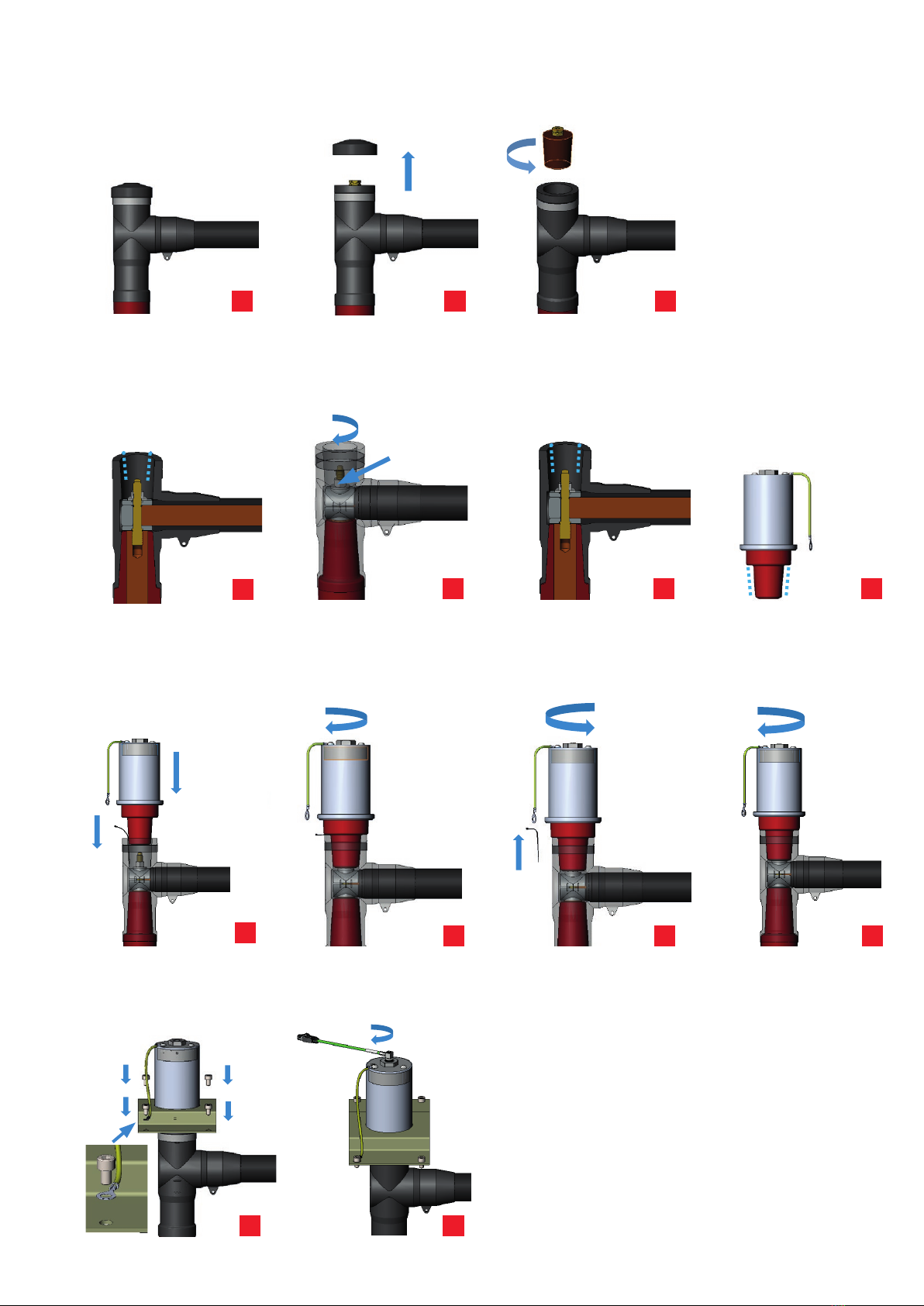
1step– removetheplugcover,seepicture1
2step– removetheinsulatingplug,seepicture2
3step– cleantheinsidesurfaceoftheadapterbypapertowel,theinsideconemustbecheckedthatthereisno
pollutionorforeignparticles(e.g.metalfilings,orsemiconductivelayeralongthecone,seepicture3)
4step– checkthetighteningoftheadapterhexnutrecommendedtighteningtorque50NmforM12nut,70Nm
forM16nutshallbeused,seepicture4
5step– spreadthe mounting grease NKT MV3 (215273435)on the inside adaptersurface(where is contact
between the sensor and the cable connector, see picture. 5, by brush or glove. Recheck that the inside
conesurfaceiswithoutpollutionorforeignparticles.
6step– Assurethatsensorconeis clean,coatsensorconewithmountinggrease(NKT MV3215273435). Usea
brushoraglovetospreadtheassemblypastealongthecone,seepicture6.
7step– Placethesensorconeontotheadapter.Pressthesensorconetogetherwithacleancabletie(toallowthe
air to escape) into the adapter, see picture 7aand turn the sensor in clockwise direction such that the
threadof theboltengagesin theinternalthread ofthesensorcone. Lightlytightenthe sensoratthe30
mm hexnut, see picture 7b. Withdraw the cable tie. Release the sensor by approximately 1 turn, see
picture7c.Screwthesensortightwithatorqueof30Nm,seepicture7d.
8step– Place the sensor base plate across the sensor, see picture 8. Insert the four screws M8 into the holes
providedinthesensorbaseplateandtightenthemwithatorqueof30Nm,assuringthatoneofthescrews
isusedtoconnectthesensorgroundingwiretotheswitchgearpanel,seepicture8.
9step– connecttheoutputcableofsensorKEVA36G2xtotheBNCconnector(checkthatthesecondarycablewith
thesameIDnumberasonthesensorlabelisused),seepicture9.
M16 – 70Nm
0step– originalinstallation,seepicture0
1step– removetheplugcover,seepicture1
2step– removetheinsulatingplug,seepicture2
3step– cleantheinsidesurfaceoftheadapterbypapertowel,theinsideconemustbecheckedthatthereisno
pollutionorforeignparticles(e.g.metalfilings,orsemiconductivelayeralongthecone,seepicture3)
4step– checkthetighteningoftheadapterhexnutrecommendedtighteningtorque50NmforM12nut,70Nm
forM16nutshallbeused,seepicture4
5step– spreadthe mounting grease NKT MV3 (215273435)on the inside adaptersurface(where is contact
between the sensor and the cable connector, see picture. 5, by brush or glove. Recheck that the inside
conesurfaceiswithoutpollutionorforeignparticles.
6step– Assurethatsensorconeis clean,coatsensorconewithmountinggrease(NKT MV3215273435). Usea
brushoraglovetospreadtheassemblypastealongthecone,seepicture6.
7step– Placethesensorconeontotheadapter.Pressthesensorconetogetherwithacleancabletie(toallowthe
air to escape) into the adapter, see picture 7aand turn the sensor in clockwise direction such that the
threadof theboltengagesin theinternalthread ofthesensorcone. Lightlytightenthe sensoratthe30
mm hexnut, see picture 7b. Withdraw the cable tie. Release the sensor by approximately 1 turn, see
picture7c.Screwthesensortightwithatorqueof30Nm,seepicture7d.
8step– Place the sensor base plate across the sensor, see picture 8. Insert the four screws M8 into the holes
providedinthesensorbaseplateandtightenthemwithatorqueof30Nm,assuringthatoneofthescrews
isusedtoconnectthesensorgroundingwiretotheswitchgearpanel,seepicture8.
9step– connecttheoutputcableofsensorKEVA36G2xtotheBNCconnector(checkthatthesecondarycablewith
thesameIDnumberasonthesensorlabelisused),seepicture9.
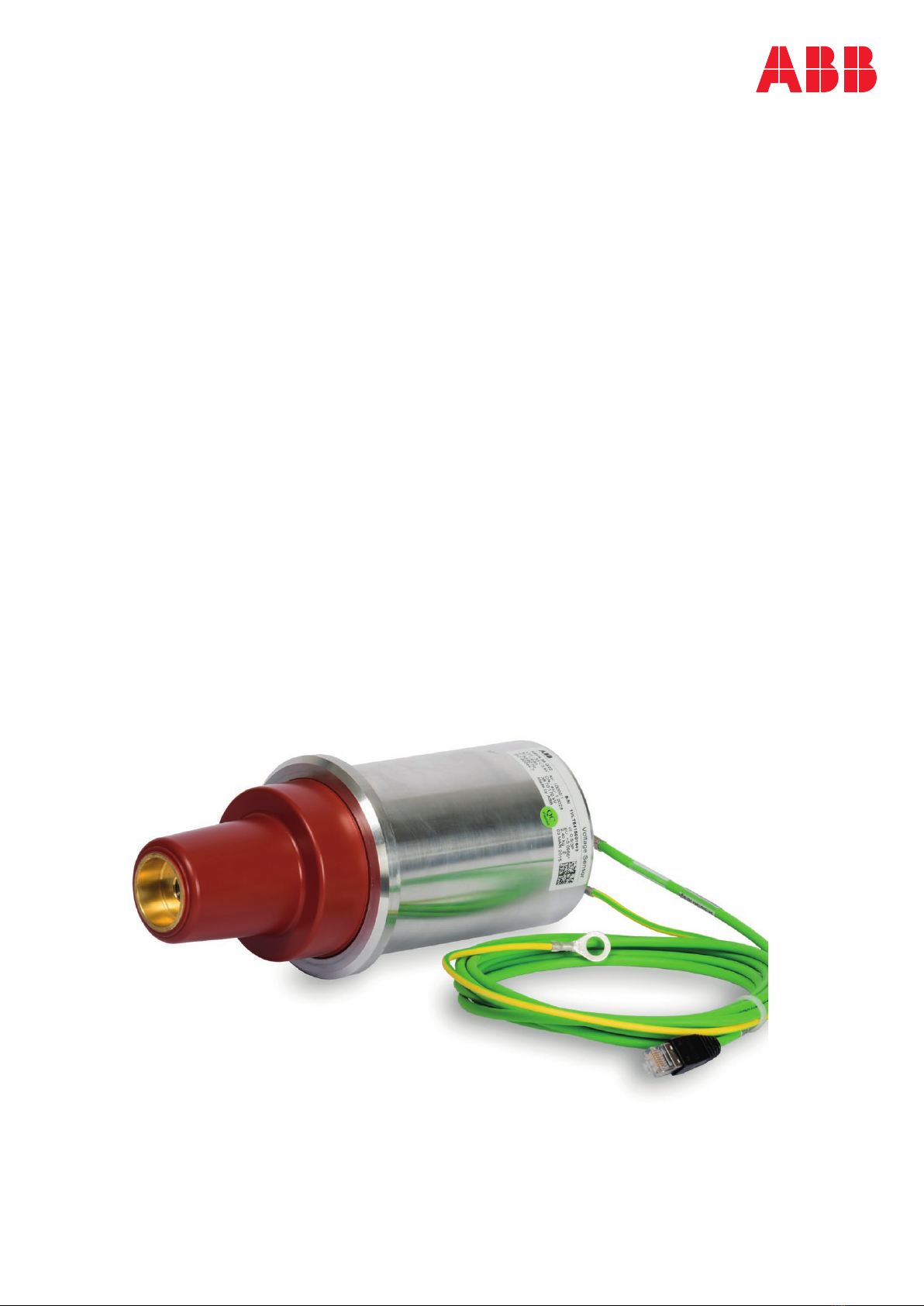
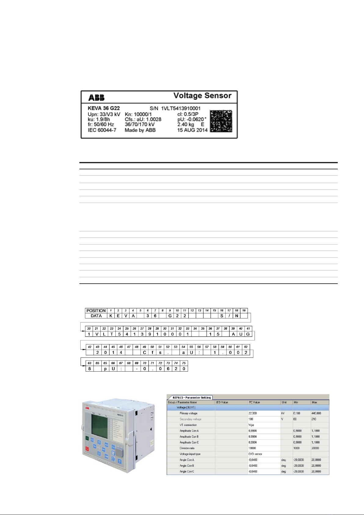
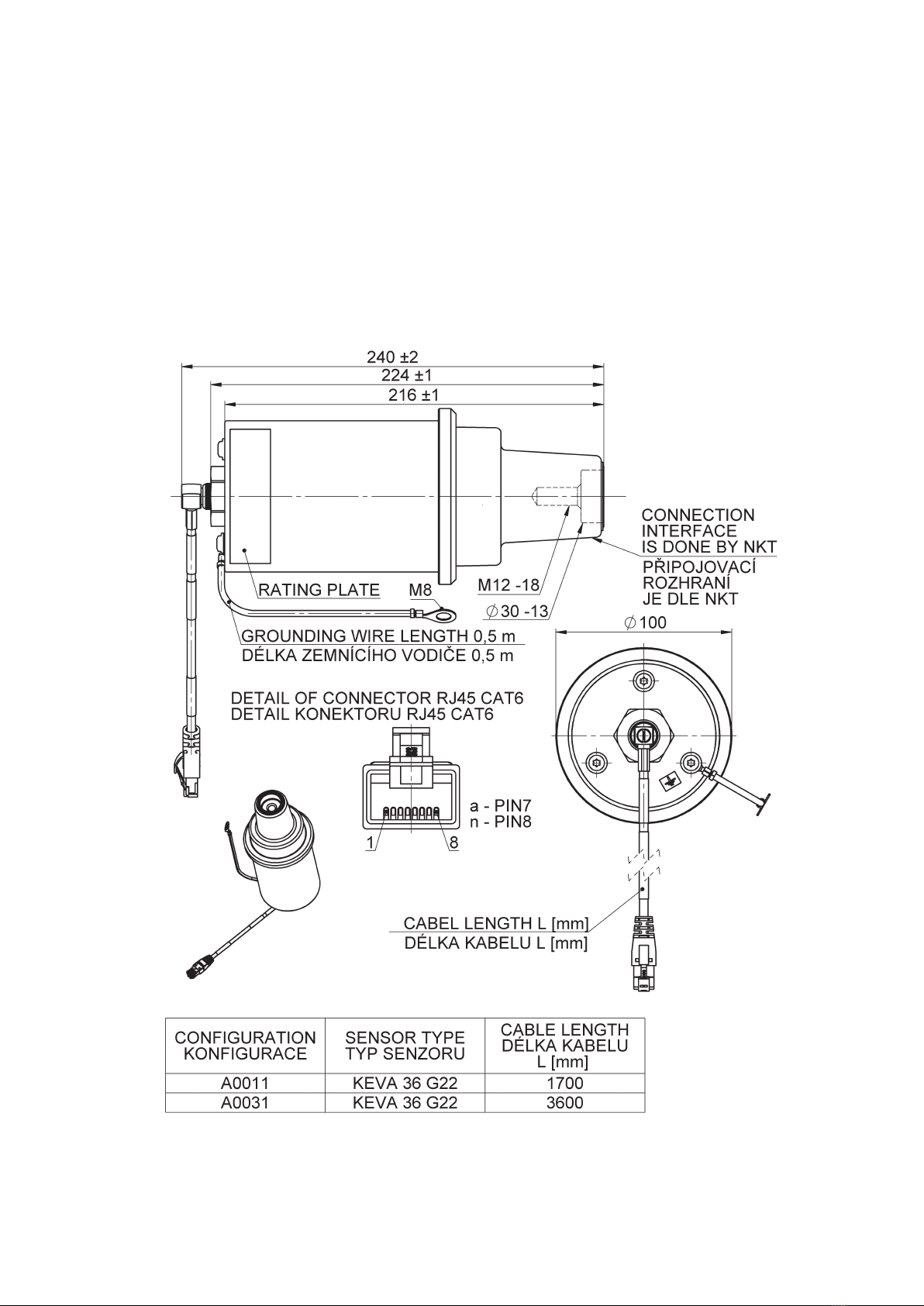
Fig.5ExampleofKEVA36G22sensorinapplication
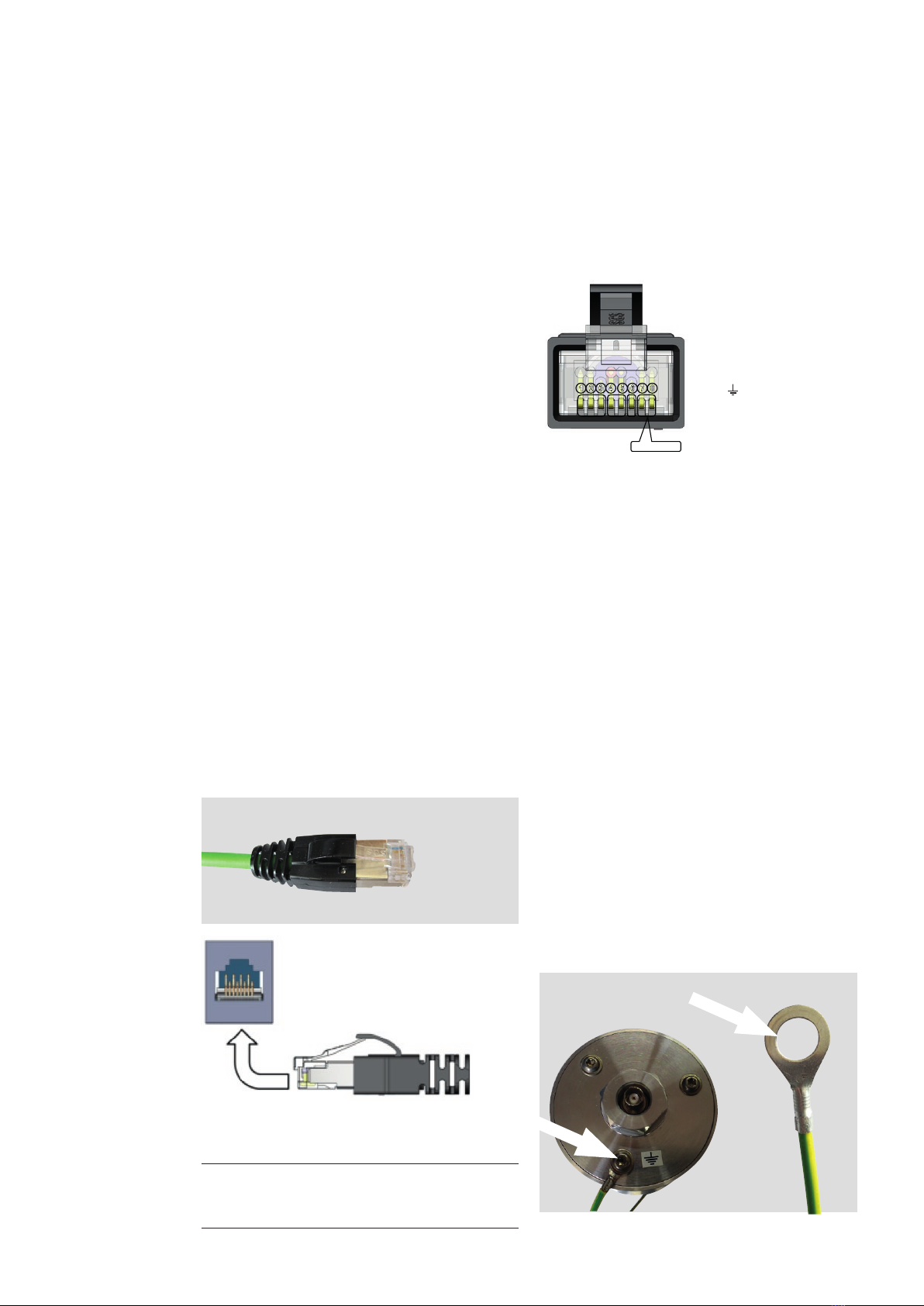
Secondarycable,secondaryconnections
The secondary cable is a special shielded cable designed to give maximum EMI shielding. The secondary cable is
inseparable part of each sensor and cannot be additionally extended, shortened, branched, modified, withdrawn or
changedduetotheguaranteeofaccuracyandperformanceofthesensor.
The cable shallbe connected directly (or via a connector adapter if needed for more information about connector
adapters and coupling adapter refer to Doc. No. 1VLC000710 Sensor Accessories) to Intelligent Electronic Device (e.g.
protectionrelay).TheelectricalshieldingofcableisconnectedtoconnectorshieldingandshallbeearthedonIEDside.The
cableshallbefixedclosetometalwallorinsertedinsideofmetalcabletrayfarfrompowercables!Theminimalbending
radius for the secondary cable is 35 mm. The cable cannot to be moved if the temperature is below 0 °C. If cable,
connectororconnectorgrommetisdamagedpleasecontactthemanufacturerforinstructions.
ConnectiontotheIED
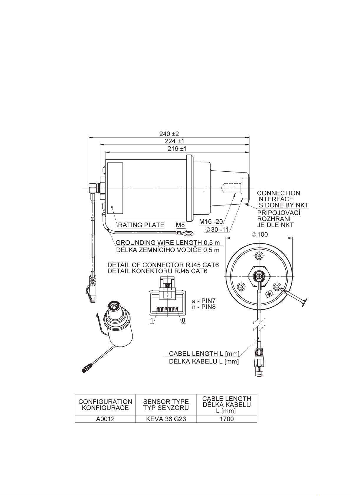
Fig.5ExampleofKEVA36G22sensorinapplication
Secondarycable,secondaryconnections
The secondary cable is a special shielded cable designed to give maximum EMI shielding. The secondary cable is
inseparable part of each sensor and cannot be additionally extended, shortened, branched, modified, withdrawn or
changedduetotheguaranteeofaccuracyandperformanceofthesensor.
The cable shallbe connected directly (or via a connector adapter if needed for more information about connector
adapters and coupling adapter refer to Doc. No. 1VLC000710 Sensor Accessories) to Intelligent Electronic Device (e.g.
protectionrelay).TheelectricalshieldingofcableisconnectedtoconnectorshieldingandshallbeearthedonIEDside.The
cableshallbefixedclosetometalwallorinsertedinsideofmetalcabletrayfarfrompowercables!Theminimalbending
radius for the secondary cable is 35 mm. The cable cannot to be moved if the temperature is below 0 °C. If cable,
connectororconnectorgrommetisdamagedpleasecontactthemanufacturerforinstructions.
ConnectiontotheIED
0step– originalinstallation,seepicture0
1step– removetheplugcover,seepicture1
2step– removetheinsulatingplug,seepicture2
3step– cleantheinsidesurfaceoftheadapterbypapertowel,theinsideconemustbecheckedthatthereisno
pollutionorforeignparticles(e.g.metalfilings,orsemiconductivelayeralongthecone,seepicture3)
4step– checkthetighteningoftheadapterhexnutrecommendedtighteningtorque50NmforM12nut,70Nm
forM16nutshallbeused,seepicture4
5step– spreadthe mounting grease NKT MV3 (215273435)on the inside adaptersurface(where is contact
between the sensor and the cable connector, see picture. 5, by brush or glove. Recheck that the inside
conesurfaceiswithoutpollutionorforeignparticles.
6step– Assurethatsensorconeis clean,coatsensorconewithmountinggrease(NKT MV3215273435). Usea
brushoraglovetospreadtheassemblypastealongthecone,seepicture6.
7step– Placethesensorconeontotheadapter.Pressthesensorconetogetherwithacleancabletie(toallowthe
air to escape) into the adapter, see picture 7aand turn the sensor in clockwise direction such that the
threadof theboltengagesin theinternalthread ofthesensorcone. Lightlytightenthe sensoratthe30
mm hexnut, see picture 7b. Withdraw the cable tie. Release the sensor by approximately 1 turn, see
picture7c.Screwthesensortightwithatorqueof30Nm,seepicture7d.
8step– Place the sensor base plate across the sensor, see picture 8. Insert the four screws M8 into the holes
providedinthesensorbaseplateandtightenthemwithatorqueof30Nm,assuringthatoneofthescrews
isusedtoconnectthesensorgroundingwiretotheswitchgearpanel,seepicture8.
9step– connecttheoutputcableofsensorKEVA36G2xtotheBNCconnector(checkthatthesecondarycablewith
thesameIDnumberasonthesensorlabelisused),seepicture9.
0
4
7b
Fig.5ExampleofKEVA36G22sensorinapplication
Secondarycable,secondaryconnections
The secondary cable is a special shielded cable designed to give maximum EMI shielding. The secondary cable is
inseparable part of each sensor and cannot be additionally extended, shortened, branched, modified, withdrawn or
changedduetotheguaranteeofaccuracyandperformanceofthesensor.
The cable shallbe connected directly (or via a connector adapter if needed for more information about connector
adapters and coupling adapter refer to Doc. No. 1VLC000710 Sensor Accessories) to Intelligent Electronic Device (e.g.
protectionrelay).TheelectricalshieldingofcableisconnectedtoconnectorshieldingandshallbeearthedonIEDside.The
cableshallbefixedclosetometalwallorinsertedinsideofmetalcabletrayfarfrompowercables!Theminimalbending
radius for the secondary cable is 35 mm. The cable cannot to be moved if the temperature is below 0 °C. If cable,
connectororconnectorgrommetisdamagedpleasecontactthemanufacturerforinstructions.
ConnectiontotheIED
9
0step– originalinstallation,seepicture0
1step– removetheplugcover,seepicture1
2step– removetheinsulatingplug,seepicture2
3step– cleantheinsidesurfaceoftheadapterbypapertowel,theinsideconemustbecheckedthatthereisno
pollutionorforeignparticles(e.g.metalfilings,orsemiconductivelayeralongthecone,seepicture3)
4step– checkthetighteningoftheadapterhexnutrecommendedtighteningtorque50NmforM12nut,70Nm
forM16nutshallbeused,seepicture4
5step– spreadthe mounting grease NKT MV3 (215273435)on the inside adaptersurface(where is contact
between the sensor and the cable connector, see picture. 5, by brush or glove. Recheck that the inside
conesurfaceiswithoutpollutionorforeignparticles.
6step– Assurethatsensorconeis clean,coatsensorconewithmountinggrease(NKT MV3215273435). Usea
brushoraglovetospreadtheassemblypastealongthecone,seepicture6.
7step– Placethesensorconeontotheadapter.Pressthesensorconetogetherwithacleancabletie(toallowthe
air to escape) into the adapter, see picture 7aand turn the sensor in clockwise direction such that the
threadof theboltengagesin theinternalthread ofthesensorcone. Lightlytightenthe sensoratthe30
mm hexnut, see picture 7b. Withdraw the cable tie. Release the sensor by approximately 1 turn, see
picture7c.Screwthesensortightwithatorqueof30Nm,seepicture7d.
8step– Place the sensor base plate across the sensor, see picture 8. Insert the four screws M8 into the holes
providedinthesensorbaseplateandtightenthemwithatorqueof30Nm,assuringthatoneofthescrews
isusedtoconnectthesensorgroundingwiretotheswitchgearpanel,seepicture8.
9step– connecttheoutputcableofsensorKEVA36G2xtotheBNCconnector(checkthatthesecondarycablewith
thesameIDnumberasonthesensorlabelisused),seepicture9.
1
5
7c
0step– originalinstallation,seepicture0
1step– removetheplugcover,seepicture1
2step– removetheinsulatingplug,seepicture2
3step– cleantheinsidesurfaceoftheadapterbypapertowel,theinsideconemustbecheckedthatthereisno
pollutionorforeignparticles(e.g.metalfilings,orsemiconductivelayeralongthecone,seepicture3)
4step– checkthetighteningoftheadapterhexnutrecommendedtighteningtorque50NmforM12nut,70Nm
forM16nutshallbeused,seepicture4
5step– spreadthe mounting grease NKT MV3 (215273435)on the inside adaptersurface(where is contact
between the sensor and the cable connector, see picture. 5, by brush or glove. Recheck that the inside
conesurfaceiswithoutpollutionorforeignparticles.
6step– Assurethatsensorconeis clean,coatsensorconewithmountinggrease(NKT MV3215273435). Usea
brushoraglovetospreadtheassemblypastealongthecone,seepicture6.
7step– Placethesensorconeontotheadapter.Pressthesensorconetogetherwithacleancabletie(toallowthe
air to escape) into the adapter, see picture 7aand turn the sensor in clockwise direction such that the
threadof theboltengagesin theinternalthread ofthesensorcone. Lightlytightenthe sensoratthe30
mm hexnut, see picture 7b. Withdraw the cable tie. Release the sensor by approximately 1 turn, see
picture7c.Screwthesensortightwithatorqueof30Nm,seepicture7d.
8step– Place the sensor base plate across the sensor, see picture 8. Insert the four screws M8 into the holes
providedinthesensorbaseplateandtightenthemwithatorqueof30Nm,assuringthatoneofthescrews
isusedtoconnectthesensorgroundingwiretotheswitchgearpanel,seepicture8.
9step– connecttheoutputcableofsensorKEVA36G2xtotheBNCconnector(checkthatthesecondarycablewith
thesameIDnumberasonthesensorlabelisused),seepicture9.
2
7d
M12 – 50Nm
M16 – 70Nm
2.
unscrew
one turn
30 Nm
Fig.5ExampleofKEVA36G22sensorinapplication
Secondarycable,secondaryconnections
The secondary cable is a special shielded cable designed to give maximum EMI shielding. The secondary cable is
inseparable part of each sensor and cannot be additionally extended, shortened, branched, modified, withdrawn or
changedduetotheguaranteeofaccuracyandperformanceofthesensor.
The cable shallbe connected directly (or via a connector adapter if needed for more information about connector
adapters and coupling adapter refer to Doc. No. 1VLC000710 Sensor Accessories) to Intelligent Electronic Device (e.g.
protectionrelay).TheelectricalshieldingofcableisconnectedtoconnectorshieldingandshallbeearthedonIEDside.The
cableshallbefixedclosetometalwallorinsertedinsideofmetalcabletrayfarfrompowercables!Theminimalbending
radius for the secondary cable is 35 mm. The cable cannot to be moved if the temperature is below 0 °C. If cable,
connectororconnectorgrommetisdamagedpleasecontactthemanufacturerforinstructions.
ConnectiontotheIED
7a
2.
1.
1.
Fig.5ExampleofKEVA36G22sensorinapplication
Secondarycable,secondaryconnections
The secondary cable is a special shielded cable designed to give maximum EMI shielding. The secondary cable is
inseparable part of each sensor and cannot be additionally extended, shortened, branched, modified, withdrawn or
changedduetotheguaranteeofaccuracyandperformanceofthesensor.
The cable shallbe connected directly (or via a connector adapter if needed for more information about connector
adapters and coupling adapter refer to Doc. No. 1VLC000710 Sensor Accessories) to Intelligent Electronic Device (e.g.
protectionrelay).TheelectricalshieldingofcableisconnectedtoconnectorshieldingandshallbeearthedonIEDside.The
cableshallbefixedclosetometalwallorinsertedinsideofmetalcabletrayfarfrompowercables!Theminimalbending
radius for the secondary cable is 35 mm. The cable cannot to be moved if the temperature is below 0 °C. If cable,
connectororconnectorgrommetisdamagedpleasecontactthemanufacturerforinstructions.
ConnectiontotheIED
6
0step– originalinstallation,seepicture0
1step– removetheplugcover,seepicture1
2step– removetheinsulatingplug,seepicture2
3step– cleantheinsidesurfaceoftheadapterbypapertowel,theinsideconemustbecheckedthatthereisno
pollutionorforeignparticles(e.g.metalfilings,orsemiconductivelayeralongthecone,seepicture3)
4step– checkthetighteningoftheadapterhexnutrecommendedtighteningtorque50NmforM12nut,70Nm
forM16nutshallbeused,seepicture4
5step– spreadthe mounting grease NKT MV3 (215273435)on the inside adaptersurface(where is contact
between the sensor and the cable connector, see picture. 5, by brush or glove. Recheck that the inside
conesurfaceiswithoutpollutionorforeignparticles.
6step– Assurethatsensorconeisclean,coatsensorconewithmountinggrease( NKTMV3215273435).Usea
brushoraglovetospreadtheassemblypastealongthecone,seepicture6.
7step– Placethesensorconeontotheadapter.Pressthesensorconetogetherwithacleancabletie(toallowthe
air to escape) into the adapter, see picture 7aand turn the sensor in clockwise direction such that the
threadof theboltengages intheinternalthreadof thesensorcone. Lightlytightenthesensorat the30
mm hexnut, see picture 7b. Withdraw the cable tie. Release the sensor by approximately 1 turn, see
picture7c.Screwthesensortightwithatorqueof30Nm,seepicture7d.
8step– Place the sensor base plate across the sensor, see picture 8. Insert the four screws M8 into the holes
providedinthesensorbaseplateandtightenthemwithatorqueof30Nm,assuringthatoneofthescrews
isusedtoconnectthesensorgroundingwiretotheswitchgearpanel,seepicture8.
9step– connecttheoutputcableofsensorKEVA36G2xtotheBNCconnector(checkthatthesecondarycablewith
thesameIDnumberasonthesensorlabelisused),seepicture9.
3
Fig.5ExampleofKEVA36G22sensorinapplication
Secondarycable,secondaryconnections
The secondary cable is a special shielded cable designed to give maximum EMI shielding. The secondary cable is
inseparable part of each sensor and cannot be additionally extended, shortened, branched, modified, withdrawn or
changedduetotheguaranteeofaccuracyandperformanceofthesensor.
The cable shallbe connected directly (or via a connector adapter if needed for more information about connector
adapters and coupling adapter refer to Doc. No. 1VLC000710 Sensor Accessories) to Intelligent Electronic Device (e.g.
protectionrelay).TheelectricalshieldingofcableisconnectedtoconnectorshieldingandshallbeearthedonIEDside.The
cableshallbefixedclosetometalwallorinsertedinsideofmetalcabletrayfarfrompowercables!Theminimalbending
radius for the secondary cable is 35 mm. The cable cannot to be moved if the temperature is below 0 °C. If cable,
connectororconnectorgrommetisdamagedpleasecontactthemanufacturerforinstructions.
ConnectiontotheIED
8