ABB Tina 10B User manual

2TLC010042M0201 Rev.C2
Read and understand this document
Please read and understand this document before using the products. Please consult ABB
with any questions or comments.
Suitability for use
ABB shall not be responsible for conformity with any standards, codes, or regulations that
apply to the combination of products in the customer’s application or use of the product.
Third party certificates for the products are available at https://new.abb.com/low-
voltage/products/safety-products. This information by itself is not sufficient for a complete
determination of the suitability of the products in combination with the end product,
machine, system, or other application or use.
The following are some examples of applications for which particular attention must be
given. This is not intended to be an exhaustive list of all possible uses of the products, nor is
it intended to imply that the uses listed may be suitable for the products:
•Outdoor use, uses involving potential chemical contamination or electrical
interference, or conditions or uses not described in this document.
•Nuclear energy control systems, combustion systems, railroad systems, aviation
systems, medical equipment, amusement machines, vehicles, and installations
subject to separate industry or government regulations.
•Systems, machines, and equipment that could present a risk to life or property.
Please know and observe all prohibitions of use applicable to the products.
NEVER USE THE PRODUCTS FOR AN APPLICATION INVOLVING SERIOUS RISK TO LIFE OR
PROPERTY WITHOUT ENSURING THAT THE SYSTEM AS A WHOLE HAS BEEN DESIGNED TO
ADDRESS THE RISKS, AND THAT THE ABB PRODUCT IS PROPERLY RATED AND INSTALLED FOR
THE INTENDED USE WITHIN THE OVERALL EQUIPMENT OR SYSTEM.
Descriptions and examples show how the product works and can be used. It does not mean
that it fulfills the requirements for all types of machines and processes. The buyer/user is
responsible for installing and using the product according to applicable standards and
regulations. We reserve the right to make changes to the product and the documentation
without prior notice.
2TLC010042M0201 Rev.C3
Table of Contents
1Introduction ............................................................................................................................... 4
1.1 Purpose of document ................................................................................................................ 4
1.2 Intended audience...................................................................................................................... 4
1.3 Reading prerequisites................................................................................................................ 4
1.4 Special notes................................................................................................................................ 4
2Safety ...........................................................................................................................................5
2.1 Safety precautions ......................................................................................................................5
3Product description................................................................................................................... 6
4Installation...................................................................................................................................7
4.1 Installation precautions .............................................................................................................7
4.2 Testing safety functions ............................................................................................................7
5Connections ............................................................................................................................... 8
5.1 Connection examples ...............................................................................................................10
6Functions ................................................................................................................................... 11
6.1 LED Indications .......................................................................................................................... 11
6.2 Information output signal attributes.................................................................................... 11
7Maintenance ..............................................................................................................................12
7.1 Maintenance precautions ........................................................................................................12
8Troubleshooting .......................................................................................................................13
8.1 LED indications ..........................................................................................................................13
9Dimensions................................................................................................................................14
10 Technical data ...........................................................................................................................15
11 Declaration of conformity ....................................................................................................... 17

2TLC010042M0201 Rev.C4
1Introduction
1.1 Purpose of document
The purpose of this document is to describe the functions and to provide instructions for
installation, operation, maintenance and troubleshooting of the product.
1.2 Intended audience
This document is intended for authorized personnel.
1.3 Reading prerequisites
It is assumed that the reader of this document has knowledge of the following:
•Basic knowledge of ABB safety products
•Knowledge of machine safety
1.4 Special notes
Pay attention to special notes in the document:
Warning!
Risk of severe personal injury!
An instruction or procedure which, if not carried out correctly, may result in
injury to the technician or other personnel.
Caution!
Risk of damage to the equipment!
An instruction or procedure which, if not carried out correctly, may damage
the equipment.
Note!
Important or explanatory information.

2TLC010042M0201 Rev.C5
2Safety
2.1 Safety precautions
The safety precautions must be followed during installation, operation, maintenance and
troubleshooting.
It is the responsibility of the user to ensure the correct overall functionality.
Warning!
Carefully read through the entire product manual before using the device.
Warning!
The devices shall be installed by authorized personnel following applicable
Safety regulations, standards and the Machinery directive.
Warning!
Failure to comply with instructions, operation that is not in accordance
with the use prescribed in the instructions, improper installation or
handling of the device can affect the safety of people and the plant.
Warning!
For installation and prescribed use of the product, the special notes in the
instructions must be carefully observed and the technical standards
relevant to the application must be considered.
Warning!
In case of failure to comply with the instructions or standards, especially
when tampering with and/or modifying the product, any liability is
excluded.

2TLC010042M0201 Rev.C6
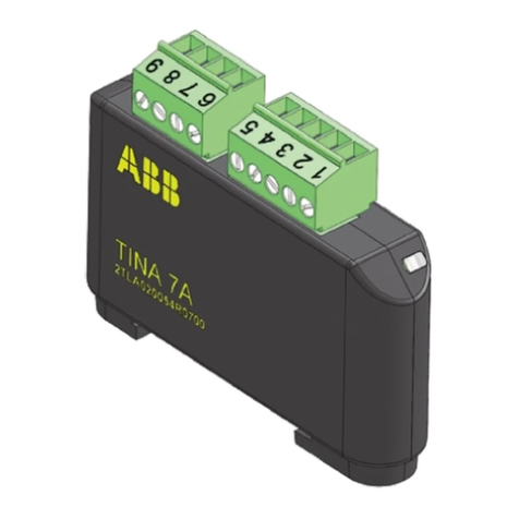
3Product description
ABB adapter units are used to adapt conventional safety devices where the safety relies on
e.g. one- or two-channel static signals, OSSD outputs, or short circuit detection, to the
DYNlink safety circuit monitored by a safety controller or a safety PLC.
Tina 10A, Tina 10B and Tina 10C are used to adapt light beams and light curtains with OSSD
outputs to the DYNlink safety circuit. This also enables complete external interconnections
using cables with M12 connectors only, which reduces the cabling to and connections in the
apparatus enclosure.
All Tina 10 units have an 8-pole female M12 connector for easy connection to an Orion receiver
and a 5-pole male M12 connector for quick installation to the DYNlink safety circuit.
Tina 10B has an extra 5-pole female M12 connector that enables local reset with a Smile reset
button.
Tina 10C also has an extra 5-pole female M12 connector but the extra connector is instead
used to connect an Orion transmitter (for power supply instead of using an extra M12-3B).
The Tina 10A/10B/10C adapter unit is intended for use in safety circuits in accordance with
EN 60204-1.

2TLC010042M0201 Rev.C7
4Installation
•Attach the cable or device to the M12 connector on Tina.
•Gently hold the Tina unit to the mounting surface and attach the unit using an M4 bolt.
•See max. tightening torques in chapter “Technical data”.
4.1 Installation precautions
Warning!
All safety functions
shall be tested before starting up the system.
4.2 Testing safety functions
After each step the status of the input can be read on the monitoring device.
Steps for testing
LED indication
DYNlink signal output
1. Interrupt the DYNlink safety
circuit before the unit to be
tested
Green/
red flashing
Shall go low
2. Close the DYNlink safety
circuit
Green
Shall generate a DYNlink
signal
3. Interrupt the DYNlink safety
circuit
(e.g. put a hand between
Orion receiver and transmitter)
Red
Shall go low

2TLC010042M0201 Rev.C8
5Connections
A)
Smile
M12
5-pole female, Tina 10B
1
Brown
+24 VDC
2
White
+24 VDC to Orion
3
Blue
Reset lamp
4
Black
Test/Reset button
5
Grey
(Muting lamp)
C
) Orion Receiver
M
12 8-pole female, Tina 10 A/B/C
1
White
Tina 10A/10C: +24 VDC
Tina 10B: Test/Reset
2
Brown
+24 VDC
3
Green
-
4
Yellow
-
5
Grey
OSSD1
6
Pink
OSSD2
7
Blue
0 VDC
8
Red
Tina 10B: Muting lamp
B)
Safety controller/Safety PLC
M12 5
-pole male, Tina 10A/B/C
1
Brown
+24 VDC
2
White
DYNlink signal input
3
Blue
0 VDC
4
Black
DYNlink signal output
5
Grey
Information
D) Orion Transmitter
M12
5-pole female, Tina 10C
1
Brown
+24 VDC
2
White
-
3
Blue
0 VDC
4
Black
-
5
Grey
-
C) Orion Receiver
A) Smile
B) Safety controller/Safety PLC
D) Orion Transmitter

2TLC010042M0201 Rev.C9
Connector seen from cable side
Note!
Which Smile reset button to use is depending on Orion model
used
– see
product catalog on ABB web.
Note!
Which cable to use between Orion and Tina 10A/B/C is depending on Orion
model used – see product catalog on ABB web.
Warning!
Information output signals
shall
never
be used for safety purpose(s).
Warning!
The OSSD connections shall not be used for purposes other than intended.
All tampering with the safety device can lead to serious risk to life.
Caution!
All cable colors according to ABB standard cables
.
Caution!
The use of shielded cable is mandatory between this unit and the rest of the
safety circuit.
M12 5-pole male connector M12 5-pole female connector
M12 8-pole male connector M12 8-pole female connector

2TLC010042M0201 Rev.C10
5.1 Connection examples
Tina 10C
Caution!
All cable colors according to ABB standard cables.

2TLC010042M0201 Rev.C11
6Functions
6.1 LED Indications
LED indication
Description
DYNlink state
Green
Safety inputs ON (protection OK)
DYNlink signal
Green/red flashing
Safety inputs ON (protection OK)
0 VDC, DYNlink interrupted
before this unit
Red
Safety input OFF
0 VDC or DYNlink signal
Safety input
s at any state
+24 VDC connected to
DYNlink signal input (pin
-2)
or interrupted in this unit
6.2 Information output signal attributes
The information output of the unit is set depending on the state of the safety inputs:
Safety inputs (OSSD1 and OSSD2)
Information output
One or both safety inputs OFF
Low
Both safety inputs ON
High
The delay for switching the information output signal:
Information output signal switch
High -> Low
Low -> High
Delay
~ 160 ms
~ 2 ms
Note!
If one or both safety inputs are OFF longer than 70 ms the information
output is set low for
approximately 1.2 s. If any of the safety inputs stay OFF
the information output stays low. If any of the safety
inputs are OFF for less
than 50 ms the information output will stay high.
Warning!
Information output signals
shall
never
be used for safety purpose(s).

2TLC010042M0201 Rev.C12
7Maintenance
Maintenance shall be done in accordance with a risk assessment for the individual
application.
7.1 Maintenance precautions
Warning!
The safety functions and the mechanics shall be tested regularly
, at least once
every year to confirm that all the safety functions are working properly.
Warning!
In
case of breakdown or damage to the product, contact ABB. Do not try to
repair the product yourself since it may accidentally cause permanent
damage to the
product, impairing the safety of the device which in turn could
lead to serious injury to personnel.

2TLC010042M0201 Rev.C13
8Troubleshooting
8.1 LED indications
LED indication
Probable cause
Action
Red
Device interrupted
Check status of the device.
Bad connection
to the
device
Check
cable to the light beam and
fasten carefully.
+24 VDC connected to
DYNlink signal input
(pin
-2)
Check if there is +24 VDC on
DYNlink signal input
(pin-2). If yes,
check cable connections or the
unit before.
No LED
light
Loss of power supply
Check +24
VDC / 0 VDC power
supply.
Green (but no DYNlink
output detected)
Defective DYNlink signal
input to unit
Check the DYNlink input or the unit
before.
Weak lights or red and
green lights at the
same time
Unit is defective
Replace the unit.
Warning!
Replace defective unit with a new one and never bypass the safety circuit
using Tina 1A or any other solution.

2TLC010042M0201 Rev.C14
9Dimensions
All dimensions are in mm.
Tina 10A
Tina 10B
Tina 10C
13,4
11,2
11,2
13,4
11,2
13,4

2TLC010042M0201 Rev.C15
10 Technical data
Further information about the product and accessories is found at:
new.abb.com/low-voltage/products/safety-products
Stated technical data apply when power supply voltage is +24 VDC and ambient temperature
is +25 °C, unless stated otherwise.
Manufacturer
Address
ABB
Electrification Sweden AB
SE
-721 61 Västerås
Sweden
Order
code/Ordering data
2TLA020054R1210: Tina 10A v2 Adapter unit
2TLA020054R1310: Tina 10B v2 Adapter unit
2TLA020054R1610: Tina 10C v2 Adapter unit
Power supply (Orion supply excluded)
Required power supply type
PELV/SELV, n
ot intended to be connected to a DC
distribution network.
Note:
A DC distribution network is defined in
IEC
61326-3-1:2017 as “Local DC electricity supply
network in the infrastructure of a certain site or
building intended for connection of any type of
equipment”.
Operating voltage
+24 VDC ±20 %
Total c
urrent consumption
Nominal: 25 mA
Maximum:
35 mA
Note:
Total current consumption is the supply current when there is no information
output current. Valid over the operating voltage and ambient temperature range.
DYNlink signal
DYNlink Input signal voltage
Minimum: 8 V
RMS
Maximum: 15 VRMS
DYNlink
Output signal voltage
Minimum: 8 V
RMS
Maximum: 15 VRMS
Note:
The purpose of stating the voltage in RMS is to facilitate the measurement of the
square-wave DYNlink signal with a multimeter.
Time delay between DYNlink
input and output signal (T
DELAY)
Maximum:
120
µ
s
Information output
Output voltage high
low
Nominal: Operating voltage
- 2 VDC
Maximum: 2 VDC
Output current
Maximum: 10 mA
OSSD inputs
Input current per channel
Nominal: 10 mA
General
Protection class
IP67
Ambient temperature
Operation:
-10 to +55 °C
Storage: -10 to +55 °C
Humidity range
35 to 85 % (with no icing or condensation)

2TLC010042M0201 Rev.C16
Housing material
TPU
Connectors
Tina 10A v2: M12 8
-pole female, M12 5-pole male
Tina 10B v2: M12 8
-pole female, M12 5-pole female,
M12 5
-pole male
Tina 10C v2: M12 8
-pole female, M12 5-pole female,
M12 5
-pole male
Tightening
torque
M12 connector: 0.6 Nm
M4 bolt: 1 Nm
Size (L x W x H)
77 x 36 x 15 mm
Weight
~ 40 g
Color
Black
Directives / Harmonized standards
Conformity
European Machinery Directive 2006/42/EC
EN ISO 12100:2010
EN ISO 13849
-1:2015, EN ISO 13849-2:2012
EN 62061:2005+A1:2013+A2:2015
EN 60204
-1:2006+A1:2009
EN 60664
-1:2007
EN
61000-6-2:2005, EN 61000-6-4:2007
EN 61508:2010
IEC/EN 61508-1…7
SIL3, PFHD = 4.50·10
-9
EN 62061
SIL3
EN ISO 13849-1
PL e, category 4
Certificates
TÜV Nord, cCSAus
Information for use in USA/Canada
Pollution degree
2
Altitude
2000 m (max)
Humidity
80% max for temperatures up to 31 °C
Indoor use statement
For indoor use only

2TLC010042M0201 Rev.C17
11 Declaration of conformity
EC Declaration of conformity

2TLC010042M0201 Rev.C18
UK Declaration of conformity
This manual suits for next models
2
Table of contents
Other ABB Adapter manuals

ABB
ABB SPA-ZC 402 Guide

ABB
ABB SPA-ZC 400 Guide

ABB
ABB Tina 3A/Aps User manual

ABB
ABB FieldKey NHU200 User manual

ABB
ABB RS485 Modbus adapter User manual

ABB
ABB Busch-AudioWorld Busch-iDock 8218 U-500 User manual

ABB
ABB WBCA Series User manual

ABB
ABB FPBA-01 PROFIBUS DP Installation manual

ABB
ABB Tina 2B User manual

ABB
ABB FENA-01 User manual
Popular Adapter manuals by other brands

SMC Networks
SMC Networks SMC EZ Connect g SMCWCBT-G Quick installation guide

NEC
NEC N8104-209 user guide

Life technologies
Life technologies Invitrogen E-Gel 4466602 manual

Hirschmann
Hirschmann ACA21-USB (EEC) Startup manual

Airlink101
Airlink101 AWLL3055 Quick installation guide

ZyXEL Communications
ZyXEL Communications NWD2205 manual