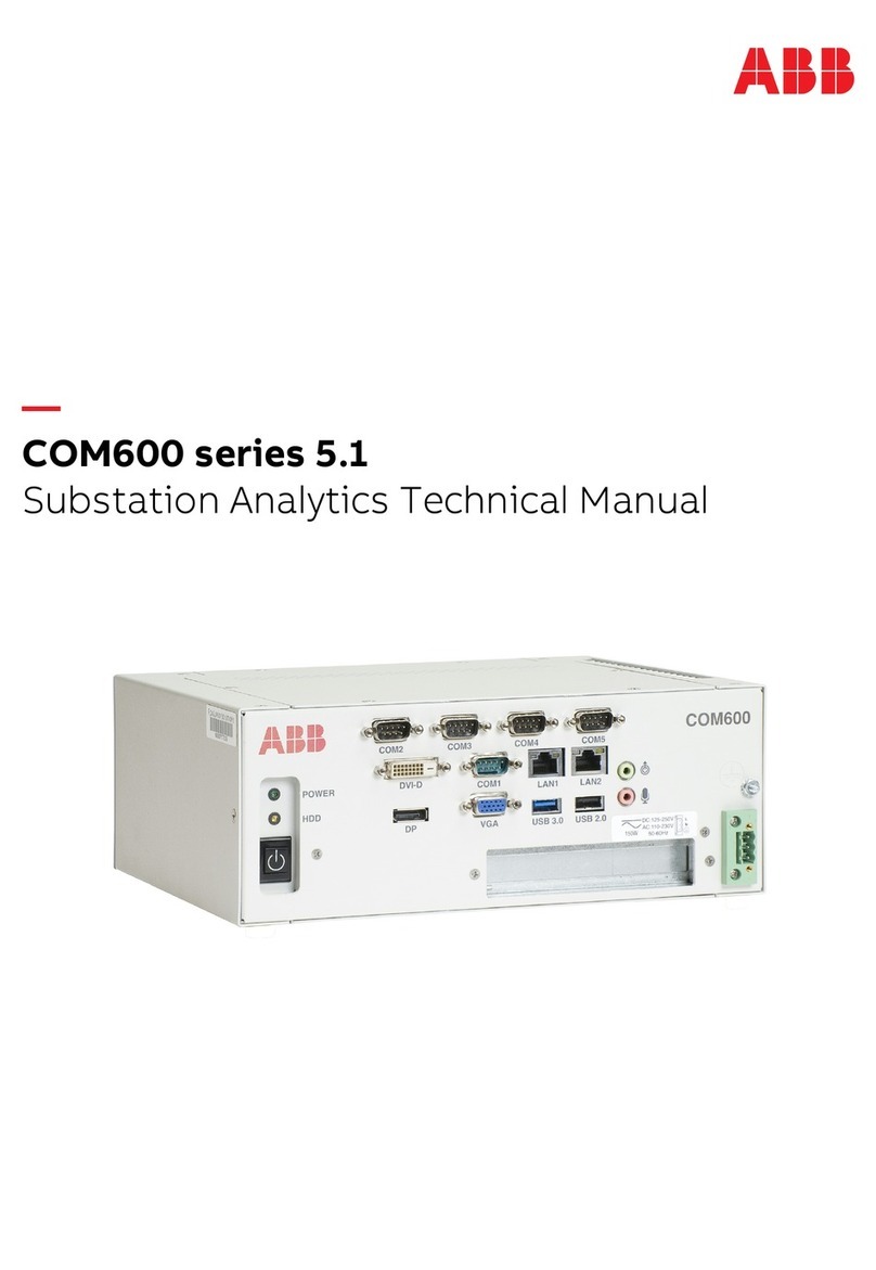
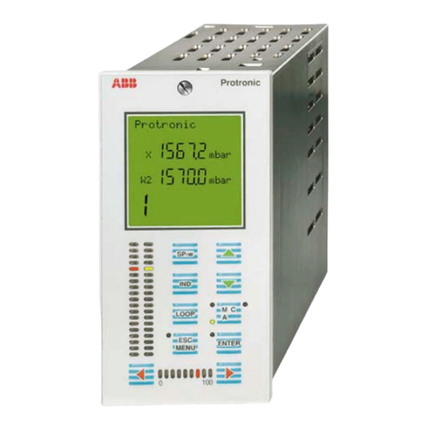
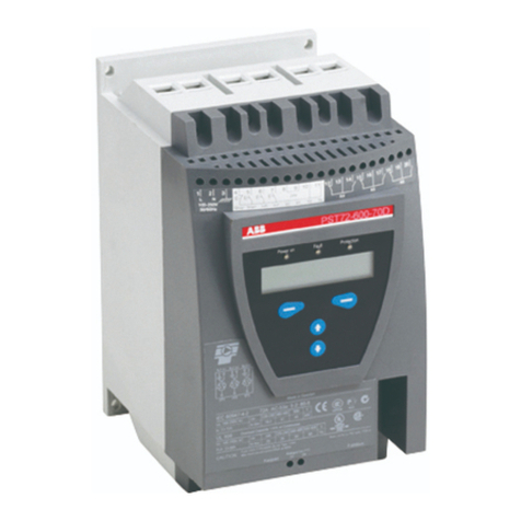
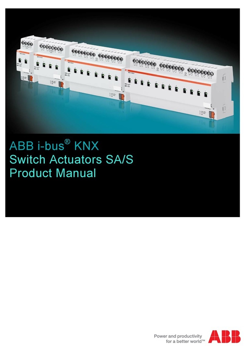
ABB Pulsar Edge User manual

Page 1
© Copyright 2021 ABB. All rights reserved.
PRODUCT MANUAL
Pulsar Edge Controller Family
Typical Controllers Typical Controllers Typical Separate Displays

Page 2
© Copyright 2021 ABB. All rights reserved.
This page intentionally left blank

Page 3
© Copyright 2021 ABB. All rights reserved.
PRODUCT MANUAL
Pulsar Edge Controller Family
Table of Contents
Table of Contents···························································································································3
Table of Figures······························································································································7
Table of Tables ·······························································································································8
Introduction ···································································································································9
Overview············································································································································· 9
Key Features······································································································································· 9
Applications ······································································································································11
Product Description····················································································································· 15
Overview············································································································································15
Configurations··································································································································15
Getting Started – Installation, Start-Up, and Basic Configuration ·········································· 19
Preparation ·······································································································································19
Safety···········································································································································19
Installation Tools ·······················································································································19
Packaging····································································································································19
Install the Pulsar Edge Controller··································································································19
Connect to the Controller ·············································································································· 23
Initial Startup of the Controller ···································································································· 24
Craft Port·········································································································································· 25
Web Interface··································································································································· 29
LAN Port as the Craft Port ······································································································ 29
Basic Controller Configuration ····································································································· 32
Operation······································································································································35
Overview··········································································································································· 35
Front Panel Display Option············································································································ 35
System Status Display ············································································································· 36
Menu Navigation Buttons ······································································································· 38
Front Panel PIN·························································································································· 38
Front Panel Menus ····················································································································40

Page 4
© Copyright 2021 ABB. All rights reserved.
Local and Remote Access Ports ··································································································· 45
Web Pages ································································································································· 45
Web Interface Structure ·········································································································· 48
Home Tab ···································································································································52
Reports Tab······························································································································· 56
Maintenance Tab ·······················································································································61
Settings Tab - Configuration···································································································62
Installation Tab ······························································································································· 90
Software Tab ····································································································································91
Controller Peripherals ················································································································· 93
One-Wire Peripheral Devices··········································································································93
QS873A Voltage/Thermal Probes···························································································93
ES771A Remote Mid-String Voltage Monitor Module························································· 95
NE872A Remote Distribution Monitor and Control Module ···················································· 99
QS871A Remote Distribution Monitor and Control Module····················································103
Troubleshooting ························································································································ 109
Checking for Defective VT-Probes······························································································ 112
Specifications ·····························································································································113
Safety ········································································································································ 117
Safety Statements··························································································································117
Precautions······································································································································117
Appendix A: Software Backup / Restore Through Network Connection································119
Application Software ···················································································································· 121
Web Pages·······································································································································122
Backup/Restore Configuration File····························································································123
Backing Up/Retrieving ·················································································································123
Restoring·········································································································································123
Appendix B: T1.317 Command Language ··················································································125
Serial Access to the Pulsar Edge Controller ··············································································125
Introduction····································································································································126
Objects, Attributes, and Related Commands··········································································· 127
Additional T1.317 Commands and Samples···············································································145
Error Messages ······························································································································153
Appendix C: Battery Functions································································································· 155
Page 5
© Copyright 2021 ABB. All rights reserved.
Float Mode······································································································································155
Slope Thermal Compensation ·····································································································155
Temperature Alarms ···············································································································156
High Temperature Compensation························································································157
Low Temperature Compensation·························································································157
Plant Battery Test··························································································································158
Boost Mode ····································································································································159
Auto-Boost Charge ·················································································································159
Redundancy Loss Function····································································································159
Battery Voltage Imbalance Detection··················································································160
Battery Recharge Current Limit···························································································· 161
Battery Parameter Defaults··································································································· 161
Appendix D: Default Configurations ·························································································163
Appendix E: Alarms and Relays································································································· 185
Alarm Relays ···································································································································185
Alarms··············································································································································185
Appendix F: SNMP······················································································································ 189
SNMP Overview······························································································································189
SNMP Operations ··························································································································190
SNMP Configuration ·····················································································································190
Community Strings ······················································································································· 191
Appendix G: Secure Protocols····································································································193
Overview··········································································································································193
Configuration································································································································· 193
Reboot Required······················································································································193
Security ·····································································································································193
Internet Protocols (IPv4 And IPv6) ·······················································································194
HTTPS (SSL) ·····························································································································195
SNMP ········································································································································· 197
SFTP···········································································································································198
SSH ··········································································································································· 200
Revision ····································································································································· 201

Page 6
© Copyright 2021 ABB. All rights reserved.
This page intentionally left blank

Page 7
© Copyright 2021 ABB. All rights reserved.
Table of Figures
Figure 1 Compact Power (CP) Line Shelves- CP841A Family of Controllers ·····························11
Figure 2 Small Power System (SPS) Line Shelves- SPS841A Family of Controllers ··················12
Figure 3 CPS6000 Series II Power System (QS) Line Shelves- QS841E Family of Controllers ·12
Figure 4 Infinity NE Converter Power Shelves- QS841E and NE841A Family of Controllers····12
Figure 5 Edge Rectifier Shelf – GCP841E Family of Controllers ················································13
Figure 6 General Power System Block Diagram········································································· 15
Figure 7 Block Diagram of Pulsar Edge CP841A Controller with the J2007001 ·······················16
Figure 8 Pulsar Edge Front Panel Display Assembly ································································· 36
Figure 9 Pulsar Edge Status Menu······························································································ 41
Figure 10 Pulsar Edge Control / Operations and History Menus ············································· 42
Figure 11 Pulsar Edge Configuration Menu (part 1) ·································································· 43
Figure 12 Pulsar Edge Configuration Menu (part 2)··································································44
Figure 13 Reports Menu··············································································································· 49
Figure 14 Maintenance Menu ······································································································ 50
Figure 15 Settings Menu·············································································································· 51
Figure 16 Installation and Software Menu ················································································· 52
Figure 17 QS873A Voltage/Thermal Probe (VT-Probe)····························································· 93
Figure 18 VT-Probe Connections to Infinity NE········································································· 94
Figure 19 ES771A Remote Voltage Monitor Module ·································································· 96
Figure 20 Four-String System Monitored For Imbalance·························································· 97
Figure 21 Same System Monitored For Imbalance with VT Probe on Every Battery ·············· 98
Figure 22 NE872A Remote Distribution Module ········································································ 99
Figure 23 NE872A ID Jumper Settings·······················································································101
Figure 24 NE872A ID Jumper Settings······················································································ 102
Figure 25 QS871A Remote Distribution Module ·······································································103
Figure 26 Slope Thermal Compensation ·················································································· 156
Figure 27: Security Configuration ·····························································································193
Figure 28: Network Settings for IPv4 and IPv6 ······································································· 194
Figure 29: Security Problem Screen Using Explorer································································ 195
Figure 30: Mismatched Address Certificate Error Screen ······················································ 196
Figure 31: HTTPS Connectivity Over IPv6 Controller Login Screen········································ 196
Figure 32: SNMP Settings Screen·······························································································197

Page 8
© Copyright 2021 ABB. All rights reserved.
Figure 33: Sample WinSCP Configuration Screen For Disable················································ 198
Figure 34: WinSCP Login Screen······························································································· 198
Figure 35: WInSCP Security Key Warning Screen····································································· 199
Figure 36: PuTTY Security Key Warning Screen·······································································200
Figure 37: PuTTY SSH Login Example Screen ··········································································200
Table of Tables
Table 1 Pulsar Edge Family Naming Convention·········································································17
Table 2 Pulsar Edge Product Examples ······················································································ 18
Table 3 Current Calculations······································································································· 69
Table 4 Power System Troubleshooting ·················································································· 109
Table 5 Supported Battery Types······························································································161
Table 6: Standard Configuration Items·····················································································163
Table 7 48V Battery Related Items ··························································································· 180
Table 8 24V Battery Related Items ··························································································· 182
Table 9 Converter Related Items ······························································································ 183
Table 10 Alarms, Alarm Relays and LEDs Assignments··························································· 185

Page 9
© Copyright 2021 ABB. All rights reserved.
Introduction
Overview
The Pulsar Edge family of controllers is part of the Pulsar family of power system controllers that
includes Pulsar Plus and Pulsar Edge controllers.
Pulsar Edge controllers were developed to be integrated into the power shelves of the Compact Power
Line (CPL), Slimline Power Systems (SPS), CPS6000 Series II power systems, Infinity NE group of
shelves, and GCP group of shelves.
These controllers were developed for both indoor and outdoor cabinet power applications.
The modular hardware and software design of the Pulsar Edge allows for easy customization for
specific applications.
Controllers provide control and alarm monitoring functions over several communication interfaces
including a standard RS-485 digital serial interface that interconnects system rectifiers, converters,
and other peripherals. Compatible rectifiers include NE, CP, NP, EP, and IP series.
Local and remote access is provided.
Features are factory configured to industry standard defaults to minimize the setup process in the
field. Customer specified factory default configuration is also available.
Key Features
• Modular design utilizing a dedicated power shelf location leaving maximum power modules
• Easy field insert or removal (hot insert)
• Standard or customer specific factory defaults supported
• Control and management of Rectifiers and Converters: Infinity NE, CPS6000, Compact Power Line, Slimline Power
System, etc.
• Extensive Battery Management features
• Management of four independent Low Voltage Disconnects (LVDs)
• Up to eight contactors assignable to the LVDs
• Load disconnects operated by low voltage, low voltage and/or time delay, remote command, or external
control signal
• Battery disconnect operated by voltage threshold, voltage threshold and/or time, Adaptive Threshold,
remote command, high battery temperature, or Emergency Power Off (EPO) signal
• Integrated contactor control for single contactor, additional contactor control through remote distribution
and control modules
• Battery recharge current limit feature
• Low and high temperature voltage compensation
• Individual adjustable slopes
• High temperature step function
• Probe Fail-Safe feature

Page 10
© Copyright 2021 ABB. All rights reserved.
• Manual and automatic Boost
• Local (manual) discharge test, remote discharge test, and periodic discharge test capability.
• Reserve time calculations with configurable threshold
• Manual time threshold for pass/fail criteria
• 1-Wire monitoring
• Up to six ES771 Mid-string voltage monitors (Configurable mid-string imbalance voltage threshold
alarm)
• Up to sixteen QS873 battery thermal probes (Configurable High, Very High, Low, and Very Low battery
temperature alarms)
• Alarm management of DC distribution
• Six configurable system alarm inputs
• Additional Factory configurable Input/Output options:
• Up to 9 configurable binary alarm inputs or
• Up to six alarm outputs or
• Combination of alarm inputs and alarm outputs
*Number of inputs/outputs depends on Pulsar Edge configuration
• Alarm output test feature
• Integrated 10/100Base-T Ethernet for local port or for Network remote monitoring
• Supports SNMP, TCP/IP, SMTP, HTTP, Telnet, FTP, and utilizes Dynamic Host Configuration Protocol (DHCP)
• SNMP Trap Test feature
• Community string support
• Remote software and configuration upgrade capability
• Internal web server compatible with standard browsers (MS Internet Explorer)
• Various Reports
• Inventory Report
• Event history log
• Statistics and Trend data
• Battery Discharge
• Energy Efficiency Algorithm
• Rectifier Group Standby/ Hold-off mapping (generator/AC load minimization)

Page 11
© Copyright 2021 ABB. All rights reserved.
Applications
The Pulsar Edge controller is available in applications involving the Compact Power Line (CPL), Slimline
Power Systems (SPS), CPS6000 Series II power systems, Infinity NE group power shelves, and GCP
group of shelves. These systems consist of an integrated controller power shelf that can be single shelf
systems with integrated distribution or multi- shelf systems with external distribution for battery or
battery-less DC power systems. The controller is available with or without a front panel display and
user interface in the CPS6000 Series II, Infinity, and SPS product lines. CPL supports display-less
options of the Pulsar Edge. Following are a few product depictions utilizing the various Pulsar Edge
controller configurations. Consult appropriate system manuals, technical field support or your local
sales representative for more details on these or other power systems that may utilize the Edge
controller.
Figure 1 Compact Power (CP) Line Shelves- CP841A Family of Controllers
Figure 2 Small Power System (SPS) Line Shelves- SPS841A Family of Controllers

Page 12
© Copyright 2021 ABB. All rights reserved.
Figure 2 Small Power System (SPS) Line Shelves- SPS841A Family of Controllers (continued)
Figure 4 Infinity NE Converter Power Shelves- QS841E and NE841A Family of Controllers
Figure 3 CPS6000 Series II Power System (QS) Line Shelves- QS841E Family of Controllers

Page 13
© Copyright 2021 ABB. All rights reserved.
Applications (Continued)
Systems that utilize the Pulsar Edge controller provide a dedicated location for the controller that
allows the maximum number of power modules to be used per shelf. Present systems locate the
controller to a dedicated position located to the left of the left most power position in the shelf. The
Pulsar Edge controller is typically pre-installed into the power shelf at the factory. However, it can be
ordered separately for spares, installed in the field, or integrated into custom systems. Access to the
controller inputs/outputs is typically located on one or two connectors located at the rear of the shelf.
There are front access shelf designs that locate these connectors to the front of the shelf. For details
on these connections consult each of the product’s individual installation guides.
The Pulsar Edge controller provides controller configurations that have a front panel RS232
asynchronous Craft port or USB connection for local terminal access. The standard RS232
asynchronous Craft port connection is a DB9 but an RJ45 serial port connection is available in specific
configurations. Easy View 2, which simulates the web page interface, is provided as the Graphical User
Interface when accessing the Craft port over the RS232 or USB connection. This program is
downloadable from the ABB home page. A front panel LCD user interface with capacitive touch soft
-keys is also available on several of the platforms for interacting with the controller and power system.
All Pulsar Edge controllers utilize the same base processor board and application code. This board is
populated and packaged differently for the different power system applications. However, software
updates performed in the factory are implemented in all configurations at a time. Since the processor
board and software is common to all Pulsar Edge configurations the controllers have the same basic
operation and functionality. These operations and features are described in this product manual.
Figure 5 Edge Rectifier Shelf – GCP841E Family of Controllers

Page 14
© Copyright 2021 ABB. All rights reserved.
This page intentionally left blank

Page 15
© Copyright 2021 ABB. All rights reserved.
Product Description
Overview
ABB rectifiers accept alternating current (ac) power and rectify it to produce direct current (dc) power
for powering external equipment (loads). Converters accept the dc output from rectifiers or other
sources and convert it to various regulated output dc levels also needed for powering external
equipment (loads). Batteries, generators, and UPS are typically used to provide backup power when ac
is lost. Batteries are connected in parallel for additional capacity with the rectifier outputs through
appropriate breakers and contactor disconnects. DC power is distributed through distribution panels
with various protectors and contactors. These rectifiers, backup systems, and distribution
components are all managed by the Pulsar Edge system controller. The following figure depicts a
generic representation of the system controller and its relationship in a power system. The
components depicted and their associated features as they relate to the system controller will be
discussed in this manual.
Configurations
The main “841” microprocessor board comprises the Pulsar Edge family of power system controllers.
This controller is designed to fit a variety of systems and applications. Systems utilizing this controller
are designed to allow the controller be quickly installed or removed from its allocated position through
a simple thumb-screw or insertion fit without having to remove input output cable attachments to the
unit. The input and output cable assemblies are connectorized and can quickly be removed or installed
Figure 6 General Power System Block Diagram

Page 16
© Copyright 2021 ABB. All rights reserved.
into the respective power shelves the controller resides. There are different configuration options for
the Pulsar Edge controller which be configured differently for these power systems.
Configuration includes the number of customer inputs or outputs, the desired front panel Craft port
interface, display option, as well as custom factory configuration. These options must be ordered and
are pre-installed at the factory.
The following figure shows a generic block diagram of the basic components of the Pulsar Edge
controller for a CPL power shelf. The exact system interconnect will vary depending on the shelf design
but this provides the basic concept of controller interconnect common to all.
Examples of Pulsar Edge controller options are defined in this section. Consult the controller ordering
guide (Pulsar_Edge-AD) and sales for the most complete and up-to-date listing. The table below
provides the basic naming nomenclature utilized for the different Pulsar Edge controller
configurations.
Figure 7 Block Diagram of Pulsar Edge CP841A Controller with the J2007001

Page 17
© Copyright 2021 ABB. All rights reserved.
Where :
1 There is a dependency on the number of outputs and inputs.
2 Secure Protocols include SNMPv3, IPv6, and HTTPS/SSH/SFTP
ZZZ
nW mR
xxx
YYY
Table 1 Pulsar Edge Family Naming Convention ZZZ 841 A_nW mR_XXX_S_YYY

Page 18
© Copyright 2021 ABB. All rights reserved.
The following table identifies controller examples. Other combinations may be available. Please consult
sales and technical field support for additional information.
3 Units without assigned Ordering Codes may still be under development or in the planning state. Other combinations may be available. Consult sales and
technical field support for additional information.
Configuration Ordering Code3Description
CP841A_0I5R CC109145356
CP841A_3C3R CC109145331
CP841A_3C3R_RJC CC109145348
tandard code.
CP841A_9C0R CC109140068
CP841A_9C0R_NT1 CC109141017 Application specific version of CP841A_9C0R.
SPS841A_3C3R CC109142238
SPS841A_0I5R CC109152377
SPS841A_0I5R_D CC109156898
SPS841A_0I5R_D_VZB1 CC109156898 Application specific version of SPS841A_0I5R_D.
QS841E_0I6R_USB CC109156535
Controller for CPS6000 Series II applications with USB front panel
interface, no supplemental inputs, six output alarm relay contacts, and
standard code.
QS841E_0I6R_USB_CS1 CC109156758 Application specific version of QSS841E_0I6R USB.
QS841E_0I6R_USB_VZT1 CC109158283 Application specific version of QSS841E_0I6R USB.
QS841E_0I6R_USB_QW1 CC109159447 Application specific version of QSS841E_0I6R USB.
QS841E_0I6R_USB_VZB1 CC109159430 Application specific version of QSS841E_0I6R USB.
NE841E_0I6R_USB CC109167053
Controller for Infinity NE-C applications with USB front panel interface,
no supplemental inputs, six output alarm relay
NE841E_0I6R_USB S 150041556 NE841E_0I6R_USB with Secure Protocols
GCP841A_0I6R_USB 150043558 Controller for Edge (GCP) applications
Table 2 Pulsar Edge Product Examples

Page 19
© Copyright 2021 ABB. All rights reserved.
Getting Started–Installation, Start-Up, and Basic Configuration
Preparation
This section outlines the sequence for installing and quickly configuring the Pulsar Edge controller into
a typical power system. A sample system will be illustrated here as an example but the individual
installation start-up guides must be consulted for specific shelves. Some power system shelf
configurations will be shipped from the factory with the controller pre-installed.
Safety
Read and follow all safety statements, warnings, and precautions in the Safety section of this manual
and manuals of all other equipment before installing, maintaining or repairing the equipment.
Installation Tools
You will need the following tools to install and test the Power System:
Packaging
• All packages must be opened with a box cutter with the blade minimally exposed to cut only the sealing tape.
• Save all packaging material until the system has been powered up and all parts are operating within specifications.
The shipping package may be used to return defective parts.
Install the Pulsar Edge Controller
The Pulsar Edge is easily slid in and out of a dedicated position in the shelf. Some shelf configurations
will have the controller factory preinstalled. This section primarily uses the Compact Power Line
controller as an example but the information provided is valid for other system configurations and
must be used with information in the Installation Start-Up documentation for each specific system.
Before applying power, a few basic controller configurations may be required. The following describes
steps for this initial configuration.
• Wire cutters and strippers
• Heat shrink gun
• 5/16-inch (8 mm) hex driver
• 1/4-inch hex driver
• Digital meter with an accuracy of ±0.02%
• Screw drivers (flat-blade and Phillips)
• ESD wrist strap
• Assortment of socket wrenches and drivers
• Test cable
• Protective canvas
• Insulating rubber mat
• Windows-based personal computer laptop (PC)
and cable to connect the PC communications port
to the local port of the controller or a CAT5 LAN
cable.

Page 20
© Copyright 2021 ABB. All rights reserved.
Step Action
Connection For ESD Prevention
Attach an ESD wrist strap or equivalent to an appropriate ESD grounding connector on your frame or system.
Grounding the System
earth ground.
for other power systems.
Captive Screw
Table of contents
Other ABB Controllers manuals

ABB
ABB i-bus KNX ABA/S 1.2.1 User manual

ABB
ABB ARC600 User manual

ABB
ABB MS116 User manual

ABB
ABB ACS150 series User manual

ABB
ABB ACS 501 Installation and operation manual

ABB
ABB ACH550-UH HVAC Instruction manual

ABB
ABB RVC User manual

ABB
ABB IRC5 Compact User manual

ABB
ABB C1900RC User manual

ABB
ABB i-bus SA/S 2.6.2.1 User manual
Popular Controllers manuals by other brands

MVE
MVE Automation Series Quick reference guide

Dresser
Dresser RB 4000 DN100 instruction manual

Mitsubishi
Mitsubishi FX3G Series user manual

Mitsubishi Electric
Mitsubishi Electric MR-J5D-G-N1 user manual

Mitsubishi Electric
Mitsubishi Electric MELSERVO-J2S-S061 Specifications and Instruction Manual

Anemostat
Anemostat KMC Conquest Application guide