manuals.online logo
Brands
  1. Home
  2. •
  3. Brands
  4. •
  5. ABB
  6. •
  7. DC Drive
  8. •
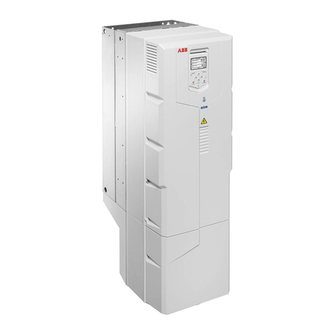
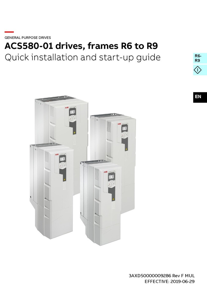
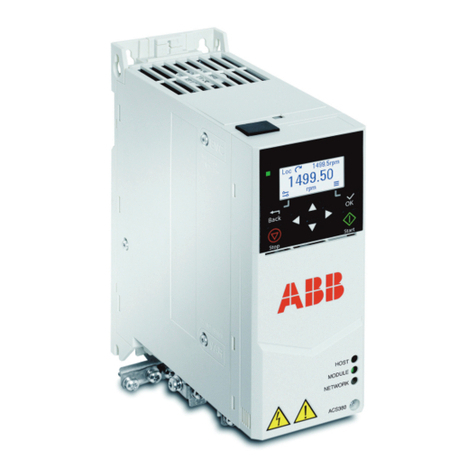
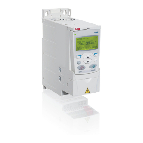
  9. ABB ACH580-01 Series User manual

ABB ACH580-01 Series User manual

Other manuals for ACH580-01 Series

12

This manual suits for next models

6

Other ABB DC Drive manuals

ABB ACS1000 User manual

ABB

ABB ACS1000 User manual

ABB ACH550-UH HVAC User manual

ABB

ABB ACH550-UH HVAC User manual

ABB ACS880-07C User manual

ABB

ABB ACS880-07C User manual

ABB ACS 400 User manual

ABB

ABB ACS 400 User manual

ABB ACS355 series User manual

ABB

ABB ACS355 series User manual

ABB ACS880-37 User manual

ABB

ABB ACS880-37 User manual

ABB HP CP500 User manual

ABB

ABB HP CP500 User manual

ABB ACS580 Series User manual

ABB

ABB ACS580 Series User manual

ABB ACH550 series User manual

ABB

ABB ACH550 series User manual

ABB ACS550 Series User manual

ABB

ABB ACS550 Series User manual

ABB ACS580-0P User manual

ABB

ABB ACS580-0P User manual

ABB ACH580-31 User manual

ABB

ABB ACH580-31 User manual

ABB ACS580-01 Series Owner's manual

ABB

ABB ACS580-01 Series Owner's manual

ABB ACS580-01 Series Installation manual

ABB

ABB ACS580-01 Series Installation manual

ABB DCS550 Series User manual

ABB

ABB DCS550 Series User manual

ABB ACS880 Series User manual

ABB

ABB ACS880 Series User manual

ABB ACS 600 Operating and maintenance instructions

ABB

ABB ACS 600 Operating and maintenance instructions

ABB ACS355 series Owner's manual

ABB

ABB ACS355 series Owner's manual

ABB DCS800 User manual

ABB

ABB DCS800 User manual

ABB ACS380 Series User manual

ABB

ABB ACS380 Series User manual

ABB Slimline XRG1 User manual

ABB

ABB Slimline XRG1 User manual

ABB ACQ580-07 User manual

ABB

ABB ACQ580-07 User manual

ABB ACH580 Series User manual

ABB

ABB ACH580 Series User manual

ABB ACS880 Series Owner's manual

ABB

ABB ACS880 Series Owner's manual

Popular DC Drive manuals by other brands

National Instruments NI MID-7604 user guide

National Instruments

National Instruments NI MID-7604 user guide

SOMFY Maestria WT Series instructions

SOMFY

SOMFY Maestria WT Series instructions

Danfoss VLT HVAC Design guide

Danfoss

Danfoss VLT HVAC Design guide

Trane TR150 Service manual

Trane

Trane TR150 Service manual

Chamberlain Garog D Series operating manual

Chamberlain Garog

Chamberlain Garog D Series operating manual

Parker PDS Series user guide

Parker

Parker PDS Series user guide

Binks QS-5012-1-CE Service manual

Binks

Binks QS-5012-1-CE Service manual

Danfoss VLT 2800 Series Quick setup

Danfoss

Danfoss VLT 2800 Series Quick setup

YASKAWA CANopen SI-S3 Technical manual

YASKAWA

YASKAWA CANopen SI-S3 Technical manual

GE D20A6 instructions

GE

GE D20A6 instructions

Danfoss VLT AQUA Drive FC 202 operating manual

Danfoss

Danfoss VLT AQUA Drive FC 202 operating manual

Lenze PositionServo 940 user manual

Lenze

Lenze PositionServo 940 user manual

Unex MC-D-250-1000-050W-TW operating manual

Unex

Unex MC-D-250-1000-050W-TW operating manual

Geckodrive G213V manual

Geckodrive

Geckodrive G213V manual

Rockwell Automation PowerFlex 700S Programming manual

Rockwell Automation

Rockwell Automation PowerFlex 700S Programming manual

WEG DeviceNet CFW500 user manual

WEG

WEG DeviceNet CFW500 user manual

Siemens SINAMICS G List manual

Siemens

Siemens SINAMICS G List manual

Siemens SINAMICS SM150 6SL3815-7NP41-0AA1 Operating instructions & installation instructions

Siemens

Siemens SINAMICS SM150 6SL3815-7NP41-0AA1 Operating instructions & installation instructions

manuals.online logo
manuals.online logoBrands
  • About & Mission
  • Contact us
  • Privacy Policy
  • Terms and Conditions

Copyright 2025 Manuals.Online. All Rights Reserved.

—
ABB DRIVES FOR HVAC
ACH580-01 drives
Installation, Operation and Maintenance
Manual (I, O & M)
ACH580-01 HVAC Drives (1...350 HP, 0.75...250 kW)
ACH580-BCR/BDR (1...350 HP, 0.75...250 kW)
ACH580-PCR/PDR (1...350 HP, 0.75...250 kW)
ACH580-VCR/VDR (1...60 HP, 0.75...45 kW)
ACH580_Inst_Op_Maint_Rev G.book Page 1
2 ACH580 Installation, Operation and Maintenance Manual
Safety instructions
Safety instructions
These are the safety instructions which you
must obey when you install and operate the
drive and do maintenance on the drive. If you
ignore the safety instructions, injury, death or
damage can occur.
Use of warnings and notes in this
manual
Warnings tell you about conditions which can
cause injury or death, or damage to the
equipment. They also tell you how to prevent
the danger. Notes draw attention to a particular
condition or fact, or give information on a
subject.
The manual uses these warning symbols:
General safety in installation,
start-up and maintenance
These instructions are for all personnel that
install the drive and do maintenance work on it.
WARNING! Obey these instructions. If
you ignore them, injury or death, or
damage to the equipment can occur.
• Use safety shoes with a metal toe cap to
avoid foot injury. Wear protective gloves and
long sleeves. Some parts have sharp edges.
• Handle the drive carefully.
• Frames R5…R9: Lift the drive with a
lifting device. Use the lifting eyes of the
drive.
• Frames R5…R9: Do not tip the drive
over. The drive is heavy and its center of
gravity is high. An overturning drive can
cause physical injury.
• Beware of hot surfaces. Some parts, such
as heatsinks of power semiconductors,
remain hot for a while after disconnection of
the electrical supply.
• Keep the drive in its package or protect it
otherwise from dust and burr from drilling
and grinding until you install it.
• Vacuum clean the area below the drive
before the start-up to prevent the drive
cooling fan from drawing the dust inside the
drive.
• Do not cover the air inlet and outlet when the
drive runs.
• Make sure that there is sufficient cooling.
See the ACH580 Hardware Manual
(3AXD50000044839) for more information.
Electricity warning tells about hazards
from electricity which can cause injury
or death, or damage to the equipment.
General warning tells about
conditions, other than those caused by
electricity, which can cause injury or death,
or damage to the equipment.
Electrostatic sensitive devices
warning tells you about the risk of
electrostatic discharge which can cause
damage to the equipment.
ACH580_Inst_Op_Maint_Rev G.book Page 2
ACH580 Installation, Operation and Maintenance Manual 3
Safety instructions
• Before you connect voltage to the drive,
make sure that the drive covers are on.
Keep the covers on during the operation.
• Before you adjust the drive operation limits,
make sure that the motor and all driven
equipment can operate throughout the set
operation limits.
• Before you activate the automatic fault reset
or automatic restart functions of the drive
control program, make sure that no
dangerous situations can occur. These
functions reset the drive automatically and
continue operation after a fault or supply
break. If these functions are activated, the
installation must be clearly marked as
defined in IEC/EN 61800-5-1, sub-clause
6.5.3, for example, “THIS MACHINE
STARTS AUTOMATICALLY”.
• The maximum number of drive power-ups is
five in ten minutes. Too frequent power-ups
can damage the charging circuit of the DC
capacitors.
• If you have connected safety circuits to the
drive (for example, emergency stop and
Safe torque off), validate them at the start
up. For the validation of the Safe torque off,
see ACH580 HVAC control program
firmware manual (3AXD50000027537
[English]). For the validation of other safety
circuits, see the instructions provided with
them.
Note:
• If you select an external source for start
command and it is on, and the start
command is level-triggered, the drive will
start immediately after fault reset. See
parameters 20.02 Ext1 start trigger type and
20.07 Ext2 start trigger type in ACH580
HVAC control program firmware manual
(3AXD50000027537 [English]).
• When the control location is not set to Local
(text Hand is not shown on the top row of the
panel and parameter 19.19 Off mode
disable has value Off button disabled), the
stop key on the control panel will not stop
the drive.
• Frames R1…R5: Do not attempt to repair a
malfunctioning drive; contact your local
representative for replacement or repair by
authorized persons.
• Frames R6…R9: Can be repaired by
authorized persons.
Electrical safety in installation,
start-up and maintenance
Precautions before electrical work
These warnings are for all personnel who do
work on the drive, motor cable or motor.
WARNING! Frames R1 … R9: Obey
these instructions. If you ignore them,
injury or death, or damage to the equipment
can occur. If you are not a qualified electrical
professional, do not do electrical installation or
maintenance work. Go through these steps
before you begin any installation or
maintenance work.
1. Clearly identify the work location.
2. Disconnect all possible voltage sources.
Lock and tag.
• Open the main disconnector at the power
supply of the drive.
• Make sure that reconnection is not
possible.
• Disconnect any external power sources
from the control circuits.
• After you disconnect the drive, always
wait for 5 minutes to let the intermediate
circuit capacitors discharge before you
continue.
3. Protect any other energized parts in the
work location against contact.
4. Take special precautions when close to bare
conductors.
5. Measure that the installation is
de-energized.
• Use a multimeter with an impedance of at
least 1 Mohm.
ACH580_Inst_Op_Maint_Rev G.book Page 3
4 ACH580 Installation, Operation and Maintenance Manual
Safety instructions
• Make sure that the voltage between the
drive input power terminals (L1, L2, L3)
and the grounding terminal (PE) is close
to 0 V.
Frames R1…R3: Measure the voltage
between the drive UDC+ terminal and
grounding terminal (PE) with one
multimeter. As there is no UDC- terminal,
measure the voltage between the drive
T1/U terminal and grounding terminal
(PE) with another multimeter. Make sure
that the voltage difference between the
multimeters is close to 0 V.
Frames R4…R9: Measure the voltage
between the drive DC terminals (UDC+
and UDC-) and the grounding terminal
(PE) and make sure that it is close to 0 V.
6. Install temporary grounding as required by
the local regulations.
7. Ask for a permit to work from the person in
control of the electrical installation work.
If the drive does not operate according to these
steps, refer to the ACH580 Hardware Manual
(3AXD50000044839).
Additional instructions and notes
WARNING! Obey these instructions. If
you ignore them, injury or death, or
damage to the equipment can occur.
• If the drive will be connected on an IT
system (ungrounded or high-resistance-
grounded [over 30 ohms]), make sure
neither the EMC filter nor the ground-to-
phase varistor are connected (metal screws
should not be installed). Connections with
metal screws in these systems can cause
danger or damage. See section Drive
compatibility for various electrical power
systems on page 16.
Note: For other systems, connecting the
internal EMC filter will reduce the conducted
emission.
• If the drive will be connected on a corner-
grounded TN system, make sure the EMC
filter is not connected (metal screws should
not be installed). Connections with metal
screws in these systems can cause danger
or damage. See section Drive compatibility
for various electrical power systems on page
16.
Note: For other systems, connecting the
internal EMC filter (using metal screws) will
reduce the conducted emission.
• Use all ELV (extra low voltage) circuits
connected to the drive only within a zone of
equipotential bonding, that is, within a zone
where all simultaneously accessible
conductive parts are electrically connected
to prevent hazardous voltages appearing
between them. You can accomplish this by a
proper factory grounding, that is, make sure
that all simultaneously accessible
conductive parts are grounded to the
protective earth (PE) bus of the building.
• Do not do insulation or voltage withstand
tests on the drive or drive modules.
Note:
• The motor cable terminals of the drive are at
a dangerous voltage when the input power
is on, regardless of whether the motor is
running or not.
• The DC and brake resistor terminals (UDC+,
UDC-, R+ and R-) are at a dangerous
voltage.
• External wiring can supply dangerous
voltages to the terminals of relay outputs
(RO1, RO2 and RO3).
• The Safe torque off function does not
remove the voltage from the main and
auxiliary circuits. The function is not effective
against deliberate sabotage or misuse.
WARNING! Use a grounding wrist band
when you handle the printed circuit
boards. Do not touch the boards unnecessarily.
The boards contain components sensitive to
electrostatic discharge.
Grounding
These instructions are for all personnel who are
responsible for the electrical installation,
including the grounding of the drive.
ACH580_Inst_Op_Maint_Rev G.book Page 4
ACH580 Installation, Operation and Maintenance Manual 5
Safety instructions
WARNING! Obey these instructions. If
you ignore them, injury or death, or
equipment malfunction can occur, and
electromagnetic interference can increase.
• If you are not a qualified electrical
professional, do not do grounding work.
• Always ground the drive, the motor and
adjoining equipment to the protective earth
(PE) bus of the power supply. This is
necessary for the personnel safety. Proper
grounding also reduces electromagnetic
emission and interference.
• In a multiple-drive installation, connect each
drive separately to the protective earth (PE)
bus of the power supply.
• Make sure that the conductivity of the
protective earth (PE) conductors is
sufficient. See section Power cable terminal
and lead-through data on page 21. Obey the
local regulations.
• Connect the power cable shields to the
protective earth (PE) terminals of the drive.
• Standard IEC/EN & UL 61800-5-1 (section
4.3.5.5.2.) requires that as the normal touch
current of the drive is higher than 3.5 mA AC
or 10 mA DC, you must use a fixed
protective earth (PE) connection. In addition,
• install a second protective earth
conductor of the same cross-sectional
area as the original protective earthing
conductor,
or
• install a protective earth conductor with a
cross-section of at least 7 AWG
(10 mm2)Cu,
or
• install a device which automatically
disconnects the supply if the protective
earth conductor breaks.
Additional instructions for Safety
Functions
WARNING! Bypass configurations
(ACH580-VxR & ACH580-BxR) do not
support Safe Torque Off (STO) functionality in
bypass mode.
Additional instructions for
permanent magnet motor drives
Safety in installation, start-up and
maintenance
These are additional warnings concerning
permanent magnet motor drives. The other
safety instructions in this chapter are also valid.
WARNING! Obey these instructions. If
you ignore them, injury or death and
damage to the equipment can occur.
• Do not work on a drive when a rotating
permanent magnet motor is connected to it.
A rotating permanent magnet motor
energizes the drive including its power
terminals.
Before installation, start-up and maintenance
work on the drive:
• Stop the motor.
• Disconnect the motor from the drive with a
safety switch or by other means.
• If you cannot disconnect the motor, make
sure that the motor cannot rotate during
work. Make sure that no other system, like
hydraulic crawling drives, can rotate the
motor directly or through any mechanical
connection like felt, nip, rope, etc.
• Measure that the installation is de-
energized.
• Use a multimeter with an impedance of at
least 1 Mohm.
• Make sure that the voltage between the
drive output terminals (T1/U, T2/V, T3/W)
and the grounding (PE) busbar is close to
0V.
• Make sure that the voltage between the
drive input power terminals (L1, L2, L3)
and the grounding (PE) busbar is close to
0V.
• Make sure that the voltage between the
drive DC terminals (UDC+, UDC-) and
the grounding (PE) terminal is close to
0V.
ACH580_Inst_Op_Maint_Rev G.book Page 5
6 ACH580 Installation, Operation and Maintenance Manual
Safety instructions
• Install temporary grounding to the drive
output terminals (T1/U, T2/V, T3/W).
Connect the output terminals together as
well as to the PE.
Start-up and operation:
• Make sure the motor is not run over the
rated speed with dynamic/positive
displacement loads.
General safety in operation
These instructions are for all personnel that
operate the drive.
WARNING! Obey these instructions. If
you ignore them, injury or death, or
damage to the equipment can occur.
• Do not control the motor with the line side
disconnect at the drive power supply;
instead, use the control panel start and stop
keys or commands through the I/O terminals
of the drive.
• Give a stop command to the drive before
you reset a fault. If you have an external
source for the start command and the start
is on, the drive will start immediately after
the fault reset, unless you configure the
drive for pulse start. See the ACH580 HVAC
control program firmware manual
(3AXD50000027537 [English]).
• Before you activate automatic fault reset
functions of the drive control program, make
sure that no dangerous situations can occur.
These functions reset the drive
automatically and continue operation after a
fault.
Note: When the drive is not in the Hand mode,
the Off key on the control panel will not stop the
drive.
Cybersecurity disclaimer
This product is designed to be connected to
and to communicate information and data via a
network interface. It is Customer’s sole
responsibility to provide and continuously
ensure a secure connection between the
product and Customer network or any other
network (as the case may be). Customer shall
establish and maintain any appropriate
measures (such as but not limited to the
installation of firewalls, application of
authentication measures, encryption of data,
installation of anti-virus programs, etc) to
protect the product, the network, its system and
the interface against any kind of security
breaches, unauthorized access, interference,
intrusion, leakage and/or theft of data or
information. ABB and its affiliates are not liable
for damages and/or losses related to such
security breaches, any unauthorized access,
interference, intrusion, leakage and/or theft of
data or information.
ACH580_Inst_Op_Maint_Rev G.book Page 6
ACH580 Installation, Operation and Maintenance Manual 7
Contents
This manual is the Installation, Operation and Maintenance Manual for the ACH580
Drives. Complete technical details are available in the ACH580 Hardware manual,
publication number 3AXD50000044839. Complete programming information is
available in the ACH580 HVAC control program firmware manual, publication
number 3AXD50000027537.
1. To determine the type of your drive, refer to its construction code on either:
• Serial number label attached on upper part of
the top mounting plate between the mounting
holes.
• Type code label attached to the base frame – on the side of the enclosure.
2. According to the construction code, proceed to your drive’s installation, operation,
diagnostics and maintenance information:
• 01 (Wall-Mounted Single Drives) – Below.
• VCR, VDR, BCR, BDR (E-Clipse Bypass) – page 91.
• PCR, PDR (Packaged Drives with Disconnect) – page 137.
ACH580í01í052Aí4
S/N * 2173303939
U1 3ph 400/480 VAC
I2 62/52 A
ACH580−01−052A−4
Input U1 3ph 400/480 VAC
I1 52 A
F1 50/60 Hz
U2 3ph 0...U1
I2 52 A
Output
Made in USA of Foreign Parts
f2 0...500 Hz
Air cooling
IP21 Icc 100 kA
UL Type 1
ABB Oy
Hiomotie 13
00380, Helsinki
Finland
S/N * 2173303939
FRAME
R4
E211945
Construction
code
Manufacturing
year and week
ACH580_Inst_Op_Maint_Rev G.book Page 7
8 ACH580 Installation, Operation and Maintenance Manual
ACH580-01 Installation
Installation
Study these installation instructions carefully before proceeding. Failure to observe
the warnings and instructions may cause a malfunction or personal hazard.
WARNING! Before you begin read Safety instructions on page 2.
1. Check free space requirements
The drive must be installed on the wall. There are two alternative ways to install it.
Note: Do not install upside down.
Vertically alone
Frame
size
Vertical installation - Free space
Above (a)1) Below (b)2) Beside
(c)
3)
mm in mm in mm in
R1 200 7.87 150 5.91 150 5.91
R2 200 7.87 150 5.91 150 5.91
R3 200 7.87 200 7.87 150 5.91
R4 53 2.09 200 7.87 150 5.91
R5 100 3.94 200 7.87 150 5.91
R6 155 6.10 300 11.81 150 5.91
R7 155 6.10 300 11.81 150 5.91
R8 155 6.10 300 11.81 150 5.91
R9 200 7.87 300 11.81 150 5.91
3AXD00000586715.xls K
1) Free space above is measured from the frame, not from the hood used
in UL (NEMA) Type 12 frames.
Note: The height of the hood for frames R4 and R9 exceeds the
requirement of free space above for these frames.
2) Free space below is measured from the frame, not from the cable box
used in frames R1…R2 and R5…R9.
3) Free space between the drive and other objects, e.g. wall.
Frame size R4 R9
Hood height (in) 2.83 9.06
Hood height (mm) 72 230
a
b
c
ACH580_Inst_Op_Maint_Rev G.book Page 8
ACH580 Installation, Operation and Maintenance Manual 9
ACH580-01 Installation
Vertically side by side
2. Prepare for installation
Lifting R1…R4
Lift the drive only by the chassis.
Lifting R5…R8
1. Use a pallet truck to move the transport package/enclosure to the installation site.
WARNING! Frames R5…R9: Lift the drive with a lifting device. Use the lifting eyes of
the drive. The drive is heavy and its center of gravity is high. An overturning
drive can cause physical injury.
2. Use a hoist to lift the drive. (Do not place drive in final position until mounting site is
prepared.)
Unpack the drive
1. Unpack the drive.
2. Check for any damage and notify the shipper immediately if damaged components
are found.
3. Check the contents against the order and the shipping label to verify that all parts
have been received.
1) Free space above is measured from the frame, not from the hood used in
UL (NEMA) Type 12 frames.
Note: The height of the hood for frames R4 and R9 exceeds the requirement of
free space above for these frames.
2) Free space below is always measured from the drive frame, not from the
cable box.
Frame
size
Vertical installation side by side - Free space
Above (a) Below (b)1) Between (c)
mm in. mm in. mm in.
R1 200 7.87 200 7.87 0 0
R2 200 7.87 200 7.87 0 0
R3 200 7.87 200 7.87 0 0
R4 200 7.87 200 7.87 0 0
R5 200 7.87 200 7.87 0 0
R6 200 7.87 300 11.81 0 0
R7 200 7.87 300 11.81 0 0
R8 200 7.87 300 11.81 0 0
R9 200 7.87 300 11.81 0 0
a
b
a
b
c= 0
ACH580_Inst_Op_Maint_Rev G.book Page 9
10 ACH580 Installation, Operation and Maintenance Manual
ACH580-01 Installation
Tools required
To install the ACH580 you need the following:
• Screwdrivers as appropriate for the mounting hardware used, including a
T20 Torx driver for drive cover removal
• Wire stripper
• Tape measure and/or provided mounting template
• Drill
• Frame sizes R5…R9: pallet truck and hoist
• Frame sizes R5…R9: The appropriate crimping tool for power cable lugs.
• Mounting hardware: screws or nuts and bolts. The type, length and quantity of
hardware depends on the mounting surface and the frame size:
WARNING! Before installing the ACH580, ensure the input power supply to the drive
is off.
WARNING! Metal shavings or debris in the enclosure can damage electrical
equipment and create a hazardous condition. Where parts, such as conduit plates
require cutting or drilling, first remove the part. If that is not practical, cover nearby
electrical components to protect them from all shavings or debris.
Flange Mounting
Further information is in Supplement: Flange mounting kit installation,
3AXD50000201877.
Frame size Mounting hardware Qty
Metric Standard
R1...R2 M5 #10 4
R3 M6 1/4 in. 4
R5 M6 1/4 in. 6
R6…R9 M8 5/16 in. 4
Frame size Kit
R1 3AXD50000105311
R2 3AXD50000105328
R3 3AXD50000105335
R4 3AXD50000031460
R5 3AXD50000031461
R6 3AXD50000018852
R7 3AXD50000018853
R8 3AXD50000018854
R9 3AXD50000018855
ACH580_Inst_Op_Maint_Rev G.book Page 10