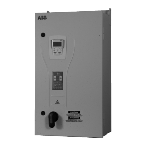
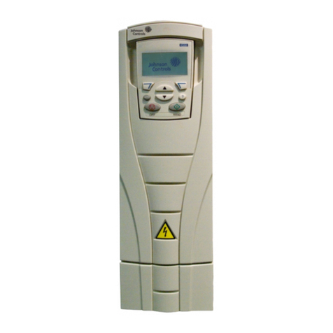
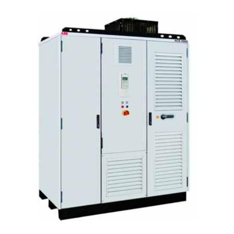
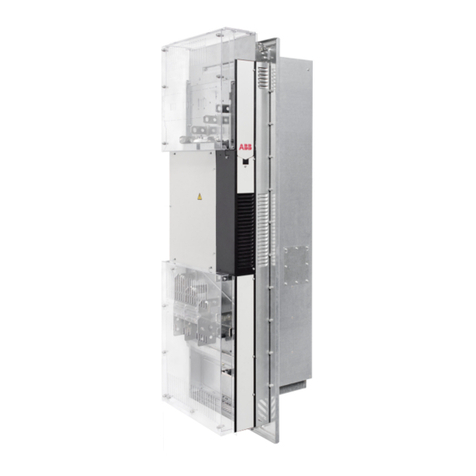
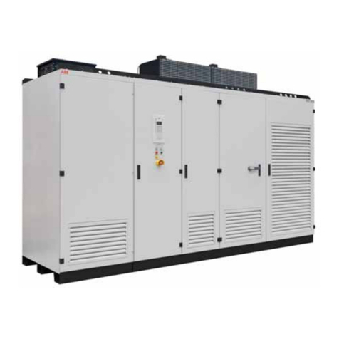
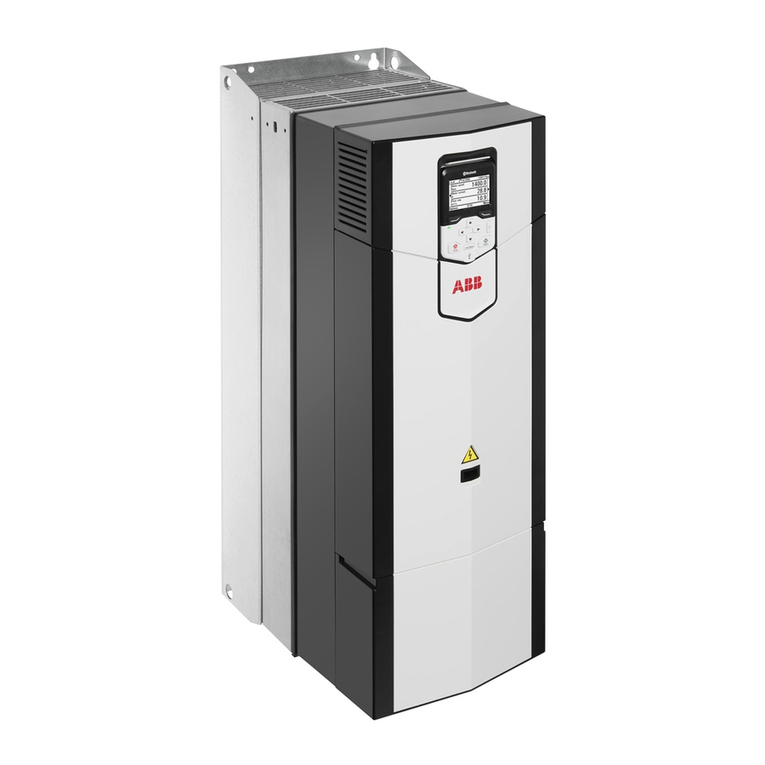
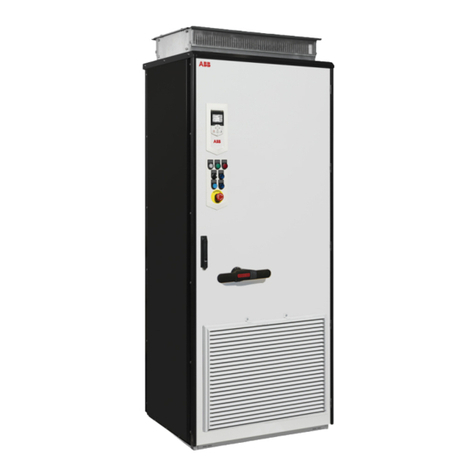
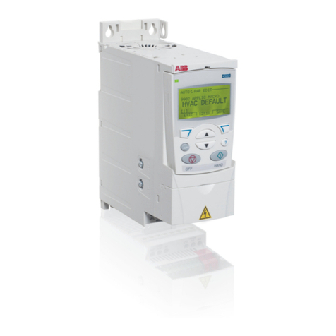
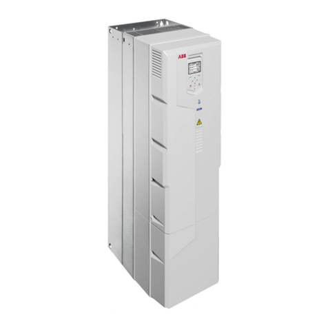
ABB ACS 600 User manual

ACS 601/604/607 AC Drives US Supplement
ACS 600 Hardware Manual Supplement


2001 ABB Inc. All Rights Reserved.
ACS 601/604/607 US Supplement
Hardware Manual Supplement
ACS600-US-04S
3AUA489002B5071 R0101 REVC
EFFECTIVE:11/12/2001
SUPERSEDES: 12/15/98


601/604/607 US Supplement i
Table of Contents
SafetyInstructions.......................................................iii
WarningsandNotes ...................................................iii
Warnings.........................................................iii
Notes............................................................ iii
SupplyConnections.................................................... v
GroundFaultProtectiveFunction.........................................vi
EmergencyStopDevices ...............................................vi
GroundConnections...................................................vi
MotorConnections.................................................... vii
Conduit ............................................................ vii
ArmoredCable....................................................... vii
MotorInsulationRequirements....................................... vii
PowerFactorCorrectionCapacitors....................................ix
OutputContactors.................................................. x
EMC ............................................................ x
MechanicalInstallation.............................................. x
Chapter 1 – Introduction . . . . . . . . . . . . . . . . . . . . . . . . . . . . . . . . . . . . . . . . . . . . . . . . . 1-1
Overview.......................................................... 1-1
IntendedAudience................................................... 1-1
WhatthisManualContains............................................ 1-1
RelatedPublications................................................. 1-2
ProductFamily...................................................... 1-2
DeliveryCheck...................................................... 1-2
Nameplate...................................................... 1-2
TypeCode...................................................... 1-2
FrameSize..................................................... 1-2
ACx600TypeCode ................................................. 1-3
Inquiries........................................................... 1-4
AppendixA–ACS/ACC600TechnicalData.................................A-1
DriveOutputRatings................................................. A-1
OutputCurrentDeratingForHighAmbientTemperature ..................A-3
Diagram........................................................ A-5
OutputCurrentDeratingForHighAltitude............................. A-6
TemperatureDeratingForHighAltitude............................... A-7
Fuses............................................................. A-8
CableEntries....................................................... A-9
ExternalControlConnections(NIOC)................................... A-11
HeatDIssipationRequirements..................................... A-12

601/604/607 US Supplement ii
CoolingAirFlowRequirements........................................ A-13
DimensionsandWeights ............................................ A-14
InputPowerConnection ............................................. A-15
MotorConnection .................................................. A-15
EfficiencyandCooling............................................... A-15
ExternalControlConnections......................................... A-16
EncoderSignals................................................ A-18
ApplicationProgram ................................................ A-19
ApplicationMacros.............................................. A-19
ProtectionFeatures.............................................. A-20
EquipmentWarrantyandLiability...................................... A-21
LimitationofLiability............................................. A-21
AppendixB–ACS/ACC600USOnlyDrawings..............................B-1

601/604/607 US Supplement iii
Safety Instructions
Overview This chapter states the safety instructions which must be followed
when installing, operating and servicing the ACx 600. If neglected,
physical injury and death may follow, or damage may occur to the AC
drive, the motor and driven equipment. The material in this chapter
must be studied before attempting any work on, or with, the unit.
Warnings and Notes This manual distinguishes two sorts of safety instructions. Warnings
are used to inform of conditions which can, if proper steps are not
taken, lead to a serious fault condition, physical injury or death. Notes
are used when the reader is required to pay special attention or when
there is additional information available on the subject. Notes are less
crucial than Warnings, but should not be disregarded.
Warnings Warnings are provided in the instruction manuals and on labels
attached to the AC drive. Readers are informed of situations that can
result in serious physical injury and/or serious damage to equipment
with the following symbols:
Notes Notes are provided in the instruction manuals to notify readers of the
need for special attention or additional information available on the
subject with the following symbols:
Dangerous Voltage Warning: warns of situations
in which a high voltage can cause physical injury
and/or damage equipment. The text next to this
symbol describes ways to avoid the danger.
General Warning: warns of situations which can
cause physical injury and/or damage equipment by
means other than electrical. The text next to this
symbol describes ways to avoid the danger.
Electrostatic Discharge Warning: warns of
situations in which an electrostatic discharge can
damage equipment. The text next to this symbol
describes ways to avoid the danger.
CAUTION! Caution aims to draw special attention to a
particular issue.
Note: Note gives additional information or points out
more information available on the subject.

Safety Instructions
iv 601/604/607 US Supplement
Installation and
Maintenance Safety These safety instructions are intended for all work on the ACx 600. In
addition to the instructions given below, there are more safety
instructions on the first pages of the appropriate hardware manual.
WARNING! All electrical installation and maintenance work on the
ACx 600 should be carried out by qualified electricians.
The ACx 600 and adjoining equipment must be properly grounded.
Do not attempt any work on a powered ACx 600. After switching off the
power, always allow the intermediate circuit capacitors 5 minutes to
discharge before working on the drive, the motor or the motor cable. It
is good practice to check (with a voltage indicating instrument) that the
drive is in fact discharged before beginning work.
The ACx 600 motor cable terminals are at a dangerously high voltage
when power is applied, regardless of motor operation.
The brake control terminals (UDC+, UDC-, R+ and R- terminals) carry
a dangerous DC voltage (over 500V).
There can be dangerous voltages inside the ACx 600 from external
control circuits when the ACx 600 input power is shut off. Exercise
appropriate care when working with the unit. Neglecting these
instructions can cause physical injury and death.
WARNING! The ACx 600 introduces electric motors, drive train
mechanisms and driven machines to an extended operating range.
The ACx 600 can be adjusted to operate the motor at speeds above
and below the speed provided by connecting the motor directly to the
power line. Before adjusting the drive and putting it into service, make
sure that the motor and all driven equipment is suitable for operation
throughout the speed range provided by the AC drive.
WARNING! If an external source for start command is selected and it is
ON, the ACx 600 will start immediately after fault reset unless the drive
is configured for 3-wire Start/Stop.
WARNING! When the control location is not set to Local (L not shown
in the status line of the display), the Stop key on the Control Panel will
not stop the drive. To stop the drive using the Control Panel you must
press the LOC/REM key and then the Stop key .
WARNING! The printed circuit boards contain integrated circuits that
are extremely sensitive to electrostatic discharge. Exercise appropriate
care when working on the unit to avoid permanent damage to the
circuits. Do not touch the boards unnecessarily.

Safety Instructions
601/604/607 US Supplement v
WARNING! There are several automatic reset functions in the ACx
600. If selected, they reset the unit and resume operation after a fault.
These functions should not be selected if other equipment is not
compatible with this kind of operation, or dangerous situations can be
caused by such action.
Supply Connections The ACx 601 does not include a disconnecting means. An input power
disconnecting means must be installed between the AC power source
and the ACx 601. The disconnecting means must conform to the
applicable safety regulations. The disconnecting means must be
locked in the open position during installation and maintenance work.
The motor must not be controlled with the supply disconnecting means;
instead, the and keys of the Control Panel or commands via
the I/O board of the ACx 600 should be used. The maximum number of
charging cycles of the d.c. capacitors of ACx 600 (i.e. power-ups by
applying power) is five in ten minutes.
ACx 6x7 units include an on-load isolating fused disconnect with a
through the door handle. This switch does not switch off power from
theEMC Linefilterof the ACx 607-0490-3/5/6, -0610-3/5/6 and -0760-
5/6 units. For ACx6x7-0490-3/5/6, -0610-3/5/6, and -0760-5/6 units
with EMC filters and for the ACx 604 module, a supply disconnecting
device must be installed in the supply, by which the electrical parts of
the unit can be separated from the power network during installation
and maintenance work. The supply disconnecting device must be
locked to the open position during installation and maintenance work.
WARNING! Never connect the line power to the ACx 600 output
terminals U2,V
2,orW
2. If frequent bypassing is required, mechanically
interlocked switches or contactors should be employed. Line voltage
applied to the output may result in permanent damage to the unit.
Operation outside the nominal input line voltage range should not be
attempted, as overvoltages can result in permanent damage to the
ACx 600.
If an ACx 601 with the integrated EMC filter (code 0 in the type code for
EMC Filters) is connected to an ungrounded power system or high
resistance grounded power system (over 30 Ohms), the power line will
be connected to ground potential through the EMC filter capacitors of
the ACx 601. This may cause danger or damage the unit. Disconnect
the EMC filter capacitors before connecting the ACx 601 to an
ungrounded power system. For detailed instructions on how to do this,
please contact your local ABB distributor.
It is not allowed to install an ACx6x4/6x7 with EMC filter options to

Safety Instructions
vi 601/604/607 US Supplement
ungrounded systems, or high resistance grounded power systems
(over 30 ohms). The main power will be connected to earth potential
through the EMC filter of the ACx 600 which may cause danger or
damage to the unit. Disconnect the EMC filter capacitors before
connecting the ACx 600 to ungrounded systems. For detailed
instructions on how to do this, please contact your local ABB
distributor.
Ground Fault
Protective Function The ACx 600 is equipped with an internal ground fault protective
function to protect the unit against ground faults in the drive, the motor
and the motor cable. This is not a personal safety or a fire protection
feature. The ground fault protective function of the ACx 600 can be set
to warning only by Parameter 30.17 for Standard Application Program
and Parameter 30.11 for Crane Application Program. The internal
ground (earth) fault protection is not in use in the 12-pulse supplied
units. For ACX 62x units, refer to the ACx 607 hardware manual
subsection labelled “Special ACx 6x7 units from 315 to 630 kW”.
The EMC filter of the ACx 600 includes capacitors connected between
the power circuit and the chassis. These capacitors increase the
ground leakage current from the AC line through the ground (PE)
connection and may cause some ground fault current circuit breakers
to trip.
Emergency Stop
Devices The person responsible for the overall design and operation of the
driven process must make sure that the installation includes
emergency stop devices and any other safety equipment that may be
needed. Pressing the STOP key on the Control Panel of ACx 600 does
not generate an emergency stop of the motor or separate the drive
from dangerous potential. A Line Contactor with provisions for a
remote power cut-off switch is available as a factory installed option for
the ACx 607. Cutting off power to the drive allows the motor to coast to
a stop.
Ground Connections The ACx 600 and adjoining equipment must be properly grounded.
The ACx 600 and the motor must be grounded at the installation site to
ensure personnel safety in all circumstances and in addition to reduce
electromagnetic emission and pick-up. Make sure that grounding
conductors are adequately sized as required by safety regulations.
In CE compliant installations and in other installations where EMC
emissions must be minimized, 360 degree high frequency grounding of
cable entries is done in order to suppress electromagnetic
disturbances. In addition, power cable shields must be connected to
the ground (PE) in order to meet safety regulations. Power cable
shields are suitable for use as equipment grounding conductors only
when the shield conductors are adequately sized as required by safety
regulations.

Safety Instructions
601/604/607 US Supplement vii
The ACx 600 ground terminals should not be connected in series in
case of a multiple installation. Incorrect grounding can cause physical
injury, death or equipment malfunction and increase electromagnetic
interference.
Motor Connections
WARNING! Operation is not allowed if the motor nominal voltage is
less than one half of the ACx 600 nominal input voltage, or the motor
nominal current is less than 1/6 of the ACx 600 nominal output current.
WARNING! Do not make any voltage tolerance or insulation resistance
test (Hi-Pot or Megger) on any part of the ACx 600. Disconnect motor
wires before making any tests of the motor or the cables between the
drive and motor.
Conduit Metallic conduit must be used for motor wiring unless armored cable or
power shield cable is used. Where conduits must be coupled together,
the joint must be bridged with a ground conductor bonded to the
conduit on each side of the joint. The conduits must also be bonded to
the drive enclosure. Use separate conduits for input power, motor,
brake resistors, and control wiring. Do not run motor wiring from more
than one drive in the same conduit.
Armored Cable If metallic conduit is not used, type MC continuous corrugated
aluminum armor cable with symmetrical grounds or power shield cable
must be used for the motor cables. If these cables are used, the motor
cables can be run in the same cable tray as other 460V or 600V power
wiring. Control and signal cables must not be run in the same tray as
power cables.
Six conductor (3 phases and 3 ground) type MC continuous corrugated
aluminum armor cable with symmetrical grounds is available from the
following suppliers. Trade names are in parentheses.
Anixter Wire & Cable (Philsheath)
BICC General Corp (Philsheath)
Rockbestos Co. (Gardex)
Oaknite (CLX)
Power shielded cables are available from Belded, Olflex, and Pirelli.
Motor Insulation
Requirements As with all AC drives employing the most modern IGBT invertor
technology, the output waveform of the ACx 600 consists of a series of
rectangular voltage pulses. Regardless of the output frequency, the
voltage of the pulses is approximately 1.35 times the input line voltage
with a very short rise time.

Safety Instructions
viii 601/604/607 US Supplement
The voltage of the pulses can be almost double at the motor terminals,
depending on the length of cable between the drive and the motor. This
in turn can cause additional stress to the motor insulation. The motor
manufacturer should be consulted regarding the characteristics of the
motor insulation system. Failure of the motor to fulfill the following
requirements may shorten its life.
The following table lists the insulation requirements for motors used
with ACx 600 AC drives.
Motor Type Nominal
AC Line Voltage Motor Insulation Requirement
ABB Motors
(manufactured
from beginning of
1998)
VN< 500 V Standard insulation system
525 V < VN≤690 V Standard insulation and dv/dt filter
or
special insulation system
Random-wound
Motors VN ≤420 V Motor insulation system must withstand VPK =1300V.
420 V < VN≤500 V If motor insulation system withstands VPK = 1600 V and 0.2
µs rise time, a dv/dt filter is not needed.
With a dv/dt filter at the output of the ACx 600, motor
insulation system must withstand VPK = 1300 V.
500 V < VN≤600 V Motor insulation system must withstand VPK =1600V.A
dv/dt filter must be used at the output of the ACx 600.
600 V < VN≤690 V Motor insulation system must withstand
VPK = 1800 V. A dv/dt filter must be used at the output of the
ACx 600.
Form-wound
Motors VN≤690 V If motor insulation system withstands VPK = 2000 V and rise
time 0.3 µs, no dv/dt filter is needed.
Symbol Definition
VNnominal power line voltage
VPK peak line to line voltage at motor terminals
Rise time:
t=0.8·VPK/(dv/dt)
Rise time is line to line voltage change rate
at motor terminals (the interval during
which the voltage changes from 10% to
90% of the whole voltage range)
VPK and tdepend on cable length. Read
the values of VPK and dv/dt from the
diagrams below.

Safety Instructions
601/604/607 US Supplement ix
Without Filter Below is a diagram of VPK and dv/dt as a function of cable length when
no dv/dt filter is used.
With dv/dt Filter Below is a diagram of VPK and dv/dt as a function of cable length with
dv/dt filter at the output of the ACx 600.
Power Factor
Correction Capacitors Power factor correction capacitors and surge absorbers must not be
connected between the drive and the motor. These devices are not
designed to be used with AC drives, and will degrade motor control
accuracy. They can cause permanent damage to the ACx 600 or
themselves due to the rapid changes in the ACx 600 output voltage.
0
0,5
1
1,5
2
2,5
3
3,5
4
4,5
5
0 50 100 150 200 250 300
dv/dt/(kV/µs)
VPK /V
N
Cable length
0
1000
500
(m)
(feet)
0
0,5
1
1,5
2
2,5
3
3,5
4
4,5
5
0 50 100 150 200 250 300
dv/dt/(kV/µs)
VPK /V
N
0
1000
500 (feet)
(m)
Cable length

Safety Instructions
x601/604/607 US Supplement
Power factor correction capacitors in parallel with the ACx 600 three
phase input can be problematic. Contact factory if questions arise.
Output Contactors If a contactor is used between the output of the ACx 600 and the motor
with DTC control mode selected, the output voltage of the ACx 600
must be controlled to zero before the contactor is opened: ACx 600
units via parameter 21.3, choose COAST. If RAMP is selected, the
output of the ACx 600 must be reduced to zero using Parameter 16.1
by giving zero V DC to the selected digital input. Otherwise the
contactor will be damaged. In scalar control the contactor can be
opened with ACx/ACC 600 running.
Varistors or RC networks (AC) or diodes (DC) should be used to
protect against voltage transients generated by contactor coils. The
protective components should be mounted as close as possible to the
contactor coils. Protective components should not be installed at the
NIOC board terminal block.
EMC When used with inductive loads (relays, contactors, motors), the relay
contacts of ACx 600 must be protected with varistors or RC networks
(AC) or diodes (DC) against voltage transients. The protective
components should not be installed at the NIOC board terminal block.
Installing control devices (contactors or relays) or control cables other
than those of the ACx 600 inside the drive enclosure is not acceptable.
Note: If safety switches, contactors, connection boxes or similar
equipment are installed between the drive and the motor, they should
be installed in a metal enclosure in a way that the conduit or motor
cable shielding runs consistently without breaks from the drive to the
motor, so the emission level will be minimized.
Mechanical Installation CAUTION! The ACx 601 weighs a considerable amount, and should
not be handled by the front cover. The unit should only be placed on its
back. Exercise appropriate care when maneuvering the unit to avoid
damage and injury. Lifting the ACx 601 is much easier and safer with
two people working together.
CAUTION! The ACx 6x7 should only be transported on the original
pallet, or with a proper lifting device using the lifting lugs on top of the
cabinet. The drive is not intended to be lifted by running lines under
the unit. The ACx 607 center of gravity is quite high, and there is a risk
ofover turningthe unit.TheACx 607canbelaidon it’sbacktofit
though confined spaces. Exercise appropriate care when
maneuvering the unit to avoid damage or injury.
CAUTION! Make sure that dust from drilling does not enter the
ACx 600 when installing. Electrically conductive dust inside the unit
may cause damage or lead to malfunction.

Safety Instructions
601/604/607 US Supplement xi
CAUTION! Do not fasten the ACx 600 by riveting or welding.
WARNING! The cooling air flows and space requirements must be
fulfilled. Special attention must be paid to cooling if units are installed in
confined spaces and user defined cabinets.

Safety Instructions
xii 601/604/607 US Supplement

601/604/607 US Supplement 1-1
Chapter 1 – Introduction
Overview This chapter describes the purpose and contents of this manual.
Thismanual isasupplement to the ACx601/604/607 ACDrive
Hardware Manuals.Theinformation contained inthismanual is:
• specific to 200 to 240 VAC product as well as 380-500 V product
distinguished by digit 11 in the ACS 600 type code being designated
as a 4. The information in the manual takes precedent over any
contradictory data found in any other user manual.
• for installations within the United States that must be installed per
the National Electric Code and local codes.
Intended Audience The intended audience of this manual are people who are responsible
for installing, starting and servicing the ACx 601 or ACx 604/607 AC
drive. The audience is expected to:
• Have a basic knowledge of physical and electrical fundamentals,
electrical wiring practices, electrical components and electrical
schematic symbols.
• Have no prior experience of ABB products.
• Have no prior experience of AC drives.
• Have no prior experience of the ACx 600 product family.
• Have no prior experience or training of installing, commissioning,
operating and servicing the ACx 600.
What this Manual
Contains Safety Instructions are placed on the first pages of this manual. The
safety instructions describe the formats for various warnings and
notations in use in this manual. The chapter also states the general
safety instructions that are intended for all work on the ACx 600.
Chapter 1 - Introduction gives information on the related publications,
product family, delivery check, and type code of the ACx 601 or ACx
604/607. Chapter 1 in this manual supersedes the entire Chapter 1 in
the ACx 601 and ACx 604/607 AC Drive Hardware Manuals.
Appendix A - ACx 604/607 Technical Data lists the ACx 600 technical
specifications. Appendix A in this manual supersedes the entire
Appendix A in the ACx 601 and ACx 604/607 AC Drive Hardware
Manuals. Refer only to the Appendix A in this manual and disregard the
Appendix A in the Hardware Manuals.

Chapter 1 – Introduction
1-2 601/604/607 US Supplement
RelatedPublications
In addition tothismanualtheACx601/604/607 ACdriveuser
documentation includes the followingpublications:
•ACx 601 or ACx604/607HardwareManual
•ACx 600 FirmwareManual
•ACx 600 DriveWindow User’sManual (optional)
• Several Option Module Manuals
• ACx 600 Technical Catalog
• ACx 600 Converter Module Installation In User Defined Cabinet
Product Family The ACx 600 product family of three phase AC drives includes
• the ACx 600 (for most applications)
• the ACC 600 (for crane drive applications)
• the ACx 600 MultiDrive (for multi drive applications)
The application programs are introduced in Appendix – A.
Study this manual carefully before installing, commissioning, operating
or servicing the drive. We expect that you have a basic knowledge of
physical and electrical fundamentals, electrical wiring practices,
electrical components and electrical schematic symbols.
Delivery Check Check that there are no signs of damage. Before attempting installation
and operation, check the information on the drive nameplate to verify
that the unit is the correct model.
Nameplate Each ACx 600 has a nameplate for identification purposes. See Figure
1-1.Thenameplate data includes atype code and aserial number
which allow individual recognition of each unit.
Type Code The ACx 600 Type Code contains information on the properties and
configuration of the drive. The Type Code Chart explains the
significance of each digit or character in the Type Code.
Frame Size ACx 600 drives are manufactured in several different chassis sizes that
are designated as Frame R2, R3, etc. Drives of several different ratings
are manufactured in the same frame. The ACx 600 rating tables on
page A-1 in Appendix A list the Frame Size used for each Type Code.
The Frame Size is not marked on the nameplate.

Chapter 1 – Introduction
601/604/607 US Supplement 1-3
Figure 1-1. ACx 600 Nameplate
ACx 600 Type Code The meaning of main selections of ACx 600 type code characters is
given in the table below. Not all selections are available for all types.
Moreinformation on selections isavailableinthe ACx 600 pricelist.
Character
no. Meaning Refer to
Example: ACx60701003000B1200901
1Product Category
A=ACDrive
2...3 Product Type
CS = Standard, CC = Crane Drive
4Product Family
6 = ACx 600
5Input Bridge
0 = 6-pulse rectifier, 1 = Regenerative 4Q IGBT Bridge,
2 = 12-pulse rectifier, 7 = Regenerative 4Q thyristor
bridge
6Construction
1 = Wall mounted, 4 = Module, 7 = Drives-MNS Cabinet
7...10 Power Rating (kVA) Appendix A:
Ratings
11 Voltage Rating
2 = 240 VAC
3 = 380/400/415 VAC
4 = 380/400/415/440/460/480/500 VAC
5 = 380/400/415/440/460/480/500 VAC
6 = 525/550/575/600/660/690 VAC
12...14 Option 1, Option 2, Option 3
15 Application Software Appendix A:
Application
Programs
x = Languages and Application Macro Options
16 Control Panel
0 = None, 1 = CDP 312 Control Panel included,
4 = Customer I/O Terminal Block X2, 5 = Options 1 + 4
U1 3-380...500V
U2 3-0...U1
I1n/I1nsq 168/198A
I2n/I2nsq 164/193A
f1 48...63Hz
f2 0...300Hz
ACS60101405...
U1 3-380...480V
U2 3-0...U1
I1hd/I1n 143/184A
I2hd/I2n 141/180A
f1 57...63Hz
f2 0...300Hz
ACS60101404...
ABB Industry Oy
Serno *1983509999*
000C150001
IEC Ratings
CE Marking
FIIND Type Code
NEMA Ratings
UL, cUL & CSA Markings
USINY Type Code
Serial Number
Bar Code
Type Code continued

Chapter 1 – Introduction
1-4 601/604/607 US Supplement
Inquiries Any inquiries about the product should be addressed to the local
distributor or ABB representative, quoting the type code and the serial
number of the unit. If the local ABB representative cannot be
contacted, inquiries should be directed to the address and phone
numbers on the back cover of this manual.
17 Degree of Protection Appendix A:
Enclosures
0 = IP 00 (chassis), A = IP 21, 2 = IP 22,
5 = IP 54, 6 = IP 00 with Coated Boards,
7 = IP 22 with Coated Boards,
8 = IP 42 with Coated Boards
9 = IP 54 with Coated Boards
B = IP 21 with Coated Boards
18 Line Input and Protection Options
19 Starter for Auxiliary Motor Fan
20 Filters Appendix A:
CE marking
0 = CE with EMC Filters (not for 690V or 12-pulse
rectifier) 230V Not CE
3 = CE with output dv/dt Filters + EMC Filters (not for
690V)
5 = Output dv/dt Filters + no EMC Filters
8 = US Standard, US conduit: No CE, no EMC filters,
9 = CE Low Voltage and Machinery Directives; No EMC
(ACx 607 only, secondary of all transformers
220 VAC) (Not valid for XTs with “4” top/top “6” top/
top w/brake chopper.)
A = 8 + dv/dt Filter
21 Braking Chopper and Cabling Direction
0 = No Brake Chopper - Bottom Entry / Bottom Exit
1 = Brake Chopper (Bottom Entry / Bottom Exit)
3 = Input Power Top Entry / Output Power Bottom Exit -
No brake chopper
4 = Input / Output Power Top Entry / Exit - No brake chop-
per (Not valid for XTs with dv/dt filters, EMC filters, or
12 pulse rectifier.)
5=Option1and3
6=Option1and4(NotvalidforXTswithdv/dtfilters,
EMC filters, or 12 pulse rectifier.)
R = NDCU-XX
22 Other Options
0 = None, 1 = Version 5.x Software, 2 = Version 5.x Har-
monized(ACx6x7only),3=Version6.xSoftware
Character
no. Meaning Refer to
Other manuals for ACS 600
3
This manual suits for next models
3
Table of contents
Other ABB DC Drive manuals

ABB
ABB ACS550-02 User manual

ABB
ABB ACS 800 Series User manual

ABB
ABB ACH580-04 User manual

ABB
ABB ACS 6000 User manual

ABB
ABB DCS800 User manual

ABB
ABB HP CP500 User manual

ABB
ABB SMISSLINE F454 Service manual

ABB
ABB MicroFlex e150 User manual

ABB
ABB ACQ80-04 Series Installation manual

ABB
ABB HSCXT3A-6B User manual

ABB
ABB ACS880 Series User manual

ABB
ABB ACS580-01 drives Owner's manual

ABB
ABB ACS880 Series Use and care manual

ABB
ABB Baldor BC200 Installation instructions

ABB
ABB ACS480 User manual

ABB
ABB ACS880-37LC User manual

ABB
ABB DCS800 User manual

ABB
ABB ACS380 Series Installation manual

ABB
ABB DCS 400 User manual

ABB
ABB ACS850-04 series User manual