manuals.online logo
Brands
  1. Home
  2. •
  3. Brands
  4. •
  5. ABB
  6. •
  7. DC Drive
  8. •
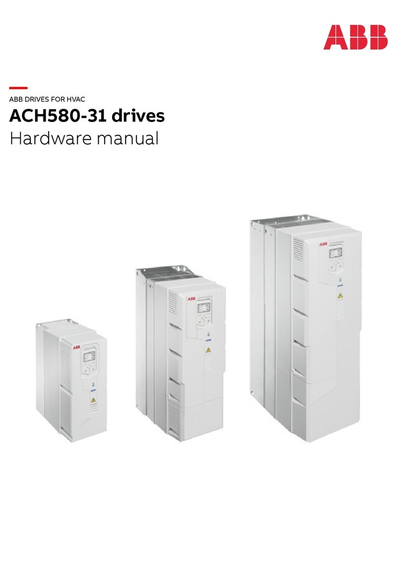
  9. ABB DriveIT ACH550-UH User manual

ABB DriveIT ACH550-UH User manual

Other ABB DC Drive manuals

ABB ACS880 Series User manual

ABB

ABB ACS880 Series User manual

ABB PSTX30 Original operating manual

ABB

ABB PSTX30 Original operating manual

ABB ACS 800 Series User manual

ABB

ABB ACS 800 Series User manual

ABB ACS880-M04 User manual

ABB

ABB ACS880-M04 User manual

ABB ACH480 User manual

ABB

ABB ACH480 User manual

ABB DCS800 User manual

ABB

ABB DCS800 User manual

ABB ACS580-07 User manual

ABB

ABB ACS580-07 User manual

ABB BUE Operating manual

ABB

ABB BUE Operating manual

ABB ACS860 Use and care manual

ABB

ABB ACS860 Use and care manual

ABB Terra HP Generation 3 CE User manual

ABB

ABB Terra HP Generation 3 CE User manual

ABB ACS880-01-046A-2 User manual

ABB

ABB ACS880-01-046A-2 User manual

ABB ACS580-01 drives Installation manual

ABB

ABB ACS580-01 drives Installation manual

ABB ACS550-CC User manual

ABB

ABB ACS550-CC User manual

ABB ACH580-31 User manual

ABB

ABB ACH580-31 User manual

ABB NETA-21 Manual

ABB

ABB NETA-21 Manual

ABB ACS880-207 User manual

ABB

ABB ACS880-207 User manual

ABB ACS800-17LC User manual

ABB

ABB ACS800-17LC User manual

ABB ACQ580-01 Series Installation manual

ABB

ABB ACQ580-01 Series Installation manual

ABB ACS880-37LC User manual

ABB

ABB ACS880-37LC User manual

ABB ACS 160 User manual

ABB

ABB ACS 160 User manual

ABB ACS550 Series User manual

ABB

ABB ACS550 Series User manual

ABB ACS6080 User manual

ABB

ABB ACS6080 User manual

ABB NOCH0070-6 Series User manual

ABB

ABB NOCH0070-6 Series User manual

ABB ACH550-UH HVAC User manual

ABB

ABB ACH550-UH HVAC User manual

Popular DC Drive manuals by other brands

National Instruments NI MID-7604 user guide

National Instruments

National Instruments NI MID-7604 user guide

SOMFY Maestria WT Series instructions

SOMFY

SOMFY Maestria WT Series instructions

Danfoss VLT HVAC Design guide

Danfoss

Danfoss VLT HVAC Design guide

Trane TR150 Service manual

Trane

Trane TR150 Service manual

Chamberlain Garog D Series operating manual

Chamberlain Garog

Chamberlain Garog D Series operating manual

Parker PDS Series user guide

Parker

Parker PDS Series user guide

Binks QS-5012-1-CE Service manual

Binks

Binks QS-5012-1-CE Service manual

Danfoss VLT 2800 Series Quick setup

Danfoss

Danfoss VLT 2800 Series Quick setup

YASKAWA CANopen SI-S3 Technical manual

YASKAWA

YASKAWA CANopen SI-S3 Technical manual

GE D20A6 instructions

GE

GE D20A6 instructions

Danfoss VLT AQUA Drive FC 202 operating manual

Danfoss

Danfoss VLT AQUA Drive FC 202 operating manual

Lenze PositionServo 940 user manual

Lenze

Lenze PositionServo 940 user manual

Unex MC-D-250-1000-050W-TW operating manual

Unex

Unex MC-D-250-1000-050W-TW operating manual

Geckodrive G213V manual

Geckodrive

Geckodrive G213V manual

Rockwell Automation PowerFlex 700S Programming manual

Rockwell Automation

Rockwell Automation PowerFlex 700S Programming manual

WEG DeviceNet CFW500 user manual

WEG

WEG DeviceNet CFW500 user manual

Siemens SINAMICS G List manual

Siemens

Siemens SINAMICS G List manual

Siemens SINAMICS SM150 6SL3815-7NP41-0AA1 Operating instructions & installation instructions

Siemens

Siemens SINAMICS SM150 6SL3815-7NP41-0AA1 Operating instructions & installation instructions

manuals.online logo
manuals.online logoBrands
  • About & Mission
  • Contact us
  • Privacy Policy
  • Terms and Conditions

Copyright 2025 Manuals.Online. All Rights Reserved.

DriveIT Low Voltage AC Drives
User’s Manual
ACH550-UH HVAC Drives (1…150 Hp)
2ACH550-UH User’s Manual
ACH550 Drive Manuals BACnet is a registered trademark of ASHRAE.
CANopen is a registered trademark of CAN in Automation
e.V.
ControlNet is a registered trademark of ControlNet
International.
DeviceNet is a registered trademark of Open DeviceNet
Vendor Association.
DRIVECOM is a registered trademark of DRIVECOM User
Organization.
Ethernet is a registered trademark of Xerox Corp.
Interbus is a registered trademark of Interbus Club.
LonWorks is a registered trademark of Echelon Corp.
Metasys is a registered trademark of Johnson Controls Inc.
Modbus and Modbus Plus are registered trademarks of
Schneider Automation Inc.
Profibus is a registered trademark of Profibus Trade Org.
Profibus-DP is a registered trademark of Siemens AG.
GENERAL MANUALS
ACH550-UH HVAC User's Manual (1…150 HP)
• Safety
•Installation
• Start-Up
• Diagnostics
• Maintenance
• Technical Data
ACH550-UH Installation Supplement (200...550 HP)
• Safety
•Installation
• Maintenance
• Technical Data
ACH550 Input Disconnect and Bypass Supplement
(1...550 HP)
• Safety
•Installation
• Start-Up
• Maintenance
• Technical Data
OPTION MANUALS
(Fieldbus Adapters, I/O Extension Modules etc., manuals
delivered with optional equipment)
Relay Output Extension Module (typical title)
•Installation
• Programming
• Fault tracing
• Technical data
© 2004 ABB Oy. All Rights Reserved.
ACH550-UH User’s Manual 3
Safety
Safety
Warning! The ACH550 adjustable speed AC drive should ONLY be installed by
a qualified electrician.
Warning! Even when the motor is stopped, dangerous voltage is present at the
Power Circuit terminals U1, V1, W1 and U2, V2, W2 and, where present, UDC+,
UDC-, BRK+ and BRK-.
Warning! Dangerous voltage is present when input power is connected. After
disconnecting the supply, wait at least 5 minutes (to let the intermediate circuit
capacitors discharge) before removing the cover.
Warning! Even when power is removed from the input terminals of the
ACH550, there may be dangerous voltage (from external sources) on the
terminals of the relay outputs R01…R03.
Warning! When the control terminals of two or more drive units are connected
in parallel, the auxiliary voltage for these control connections must be taken
from a single source which can either be one of the units or an external
supply.
Warning! The ACH550-UH is not a field repairable unit. Never attempt to repair
a malfunctioning unit; contact the factory or your local Authorized Service
Center for replacement.
Warning! The ACH550 will start up automatically after an input voltage
interruption if the external run command is on.
Warning! The heat sink may reach a high temperature. See "Technical Data" on
page 225.
Warning! If the drive will be used in a floating network, remove screws at EM1
and EM3 (Frame size R1…R4), or F1 and F2 (Frame size R5 or R6). See
diagrams on page 14 and page 15 respectively.
Note! For more technical information, contact the factory or your local ABB sales
representative.
4ACH550-UH User’s Manual
Safety
Use of Warnings and Notes
There are two types of safety instructions throughout this manual:
• Notes draw attention to a particular condition or fact, or give information on a
subject.
• Warnings caution you about conditions which can result in serious injury or death
and/or damage to the equipment. They also tell you how to avoid the danger. The
warning symbols are used as follows:
Dangerous voltage warning warns of high voltage which can cause physical
injury and/or damage to the equipment.
General warning warns about conditions, other than those caused by
electricity, which can result in physical injury and/or damage to the equipment
ACH550-UH User’s Manual 5
Table of Contents
Table of Contents
Safety
Use of Warnings and Notes . . . . . . . . . . . . . . . . . . . . . . . . . . . . . . . . . . . . . . . . 4
Table of Contents
Installation
Installation Flow Chart . . . . . . . . . . . . . . . . . . . . . . . . . . . . . . . . . . . . . . . . . . . . 7
Preparing for Installation . . . . . . . . . . . . . . . . . . . . . . . . . . . . . . . . . . . . . . . . . . 8
Installing the Drive . . . . . . . . . . . . . . . . . . . . . . . . . . . . . . . . . . . . . . . . . . . . . . 10
Start-Up
HVAC Control Panel Features . . . . . . . . . . . . . . . . . . . . . . . . . . . . . . . . . . . . . 22
Start-Up . . . . . . . . . . . . . . . . . . . . . . . . . . . . . . . . . . . . . . . . . . . . . . . . . . . . . . 23
Modes . . . . . . . . . . . . . . . . . . . . . . . . . . . . . . . . . . . . . . . . . . . . . . . . . . . . . . . . 25
Application Macros . . . . . . . . . . . . . . . . . . . . . . . . . . . . . . . . . . . . . . . . . . . . . . 35
Parameter Descriptions . . . . . . . . . . . . . . . . . . . . . . . . . . . . . . . . . . . . . . . . . . 51
Serial Communication – EFB
Overview . . . . . . . . . . . . . . . . . . . . . . . . . . . . . . . . . . . . . . . . . . . . . . . . . . . . 143
Planning . . . . . . . . . . . . . . . . . . . . . . . . . . . . . . . . . . . . . . . . . . . . . . . . . . . . . 144
Mechanical and Electrical Installation – EFB . . . . . . . . . . . . . . . . . . . . . . . . . 145
Communication Set-up – EFB . . . . . . . . . . . . . . . . . . . . . . . . . . . . . . . . . . . . 146
Activate Drive Control Functions – EFB . . . . . . . . . . . . . . . . . . . . . . . . . . . . . 147
Feedback from the Drive – EFB . . . . . . . . . . . . . . . . . . . . . . . . . . . . . . . . . . . 151
Diagnostics – EFB . . . . . . . . . . . . . . . . . . . . . . . . . . . . . . . . . . . . . . . . . . . . . 153
Modbus Protocol Technical Data . . . . . . . . . . . . . . . . . . . . . . . . . . . . . . . . . . 155
ABB Drives Profile Technical Data . . . . . . . . . . . . . . . . . . . . . . . . . . . . . . . . . 162
N2 Protocol Technical Data . . . . . . . . . . . . . . . . . . . . . . . . . . . . . . . . . . . . . . 170
FLN Protocol Technical Data . . . . . . . . . . . . . . . . . . . . . . . . . . . . . . . . . . . . . 179
BACnet Technical Data . . . . . . . . . . . . . . . . . . . . . . . . . . . . . . . . . . . . . . . . . 192
Serial Communication – FBA
Overview . . . . . . . . . . . . . . . . . . . . . . . . . . . . . . . . . . . . . . . . . . . . . . . . . . . . 193
Planning . . . . . . . . . . . . . . . . . . . . . . . . . . . . . . . . . . . . . . . . . . . . . . . . . . . . . 195
Mechanical and Electrical Installation – FBA . . . . . . . . . . . . . . . . . . . . . . . . . 196
Communication Set-up – FBA . . . . . . . . . . . . . . . . . . . . . . . . . . . . . . . . . . . . 197
Activate Drive Control Functions – FBA . . . . . . . . . . . . . . . . . . . . . . . . . . . . . 197
Feedback from the Drive – FBA . . . . . . . . . . . . . . . . . . . . . . . . . . . . . . . . . . . 200
Diagnostics – FBA . . . . . . . . . . . . . . . . . . . . . . . . . . . . . . . . . . . . . . . . . . . . . 201
ABB Drives Profile Technical Data . . . . . . . . . . . . . . . . . . . . . . . . . . . . . . . . . 203
Generic Profile Technical Data . . . . . . . . . . . . . . . . . . . . . . . . . . . . . . . . . . . . 210
Diagnostics
Diagnostic Displays . . . . . . . . . . . . . . . . . . . . . . . . . . . . . . . . . . . . . . . . . . . . 212
6ACH550-UH User’s Manual
Table of Contents
Correcting Faults . . . . . . . . . . . . . . . . . . . . . . . . . . . . . . . . . . . . . . . . . . . . . . 213
Correcting Alarms . . . . . . . . . . . . . . . . . . . . . . . . . . . . . . . . . . . . . . . . . . . . . . 218
Maintenance
Maintenance Intervals . . . . . . . . . . . . . . . . . . . . . . . . . . . . . . . . . . . . . . . . . . . 221
Heatsink . . . . . . . . . . . . . . . . . . . . . . . . . . . . . . . . . . . . . . . . . . . . . . . . . . . . . 221
Main Fan Replacement . . . . . . . . . . . . . . . . . . . . . . . . . . . . . . . . . . . . . . . . . . 222
Internal Enclosure Fan Replacement . . . . . . . . . . . . . . . . . . . . . . . . . . . . . . . 223
Capacitors . . . . . . . . . . . . . . . . . . . . . . . . . . . . . . . . . . . . . . . . . . . . . . . . . . . . 223
Control Panel . . . . . . . . . . . . . . . . . . . . . . . . . . . . . . . . . . . . . . . . . . . . . . . . . 224
Technical Data
Ratings . . . . . . . . . . . . . . . . . . . . . . . . . . . . . . . . . . . . . . . . . . . . . . . . . . . . . . 225
Input Power Connections . . . . . . . . . . . . . . . . . . . . . . . . . . . . . . . . . . . . . . . . 228
Motor Connections . . . . . . . . . . . . . . . . . . . . . . . . . . . . . . . . . . . . . . . . . . . . . 232
Control Connections . . . . . . . . . . . . . . . . . . . . . . . . . . . . . . . . . . . . . . . . . . . . 237
Efficiency . . . . . . . . . . . . . . . . . . . . . . . . . . . . . . . . . . . . . . . . . . . . . . . . . . . . 240
Cooling . . . . . . . . . . . . . . . . . . . . . . . . . . . . . . . . . . . . . . . . . . . . . . . . . . . . . . 240
Dimensions and Weights . . . . . . . . . . . . . . . . . . . . . . . . . . . . . . . . . . . . . . . . 241
Degrees of Protection . . . . . . . . . . . . . . . . . . . . . . . . . . . . . . . . . . . . . . . . . . . 244
Ambient Conditions . . . . . . . . . . . . . . . . . . . . . . . . . . . . . . . . . . . . . . . . . . . . . 244
Materials . . . . . . . . . . . . . . . . . . . . . . . . . . . . . . . . . . . . . . . . . . . . . . . . . . . . . 245
Applicable Standards . . . . . . . . . . . . . . . . . . . . . . . . . . . . . . . . . . . . . . . . . . . 245
Liability Limits . . . . . . . . . . . . . . . . . . . . . . . . . . . . . . . . . . . . . . . . . . . . . . . . . 247
Index
ACH550-UH User’s Manual 7
Installation
Installation
Study these installation instructions carefully before proceeding. Failure to observe
the warnings and instructions may cause a malfunction or personal hazard.
Warning! Before you begin read "Safety" on page 3.
Installation Flow Chart
The installation of the ACH550 adjustable speed AC drive follows the outline below.
The steps must be carried out in the order shown. At the right of each step are
references to the detailed information needed for the correct installation of the unit.
Task See
PREPARE for installation "Preparing for Installation" on page 8.
PREPARE the Mounting Location "Prepare the Mounting Location" on page 11.
REMOVE the front cover "Remove Front Cover" on page 11.
MOUNT the drive "Mount the Drive" on page 12.
INSTALL wiring "Install the Wiring" on page 12.
CHECK installation "Check Installation" on page 18.
RE-INSTALL the cover "Re-install Cover" on page 18.
APPLY power "Apply Power" on page 19.
START-UP "Start-Up" on page 20.
8ACH550-UH User’s Manual
Installation
Preparing for Installation
Lifting the Drive
Lift the drive only by the metal
chassis.
Unpack the Drive
1. Unpack the drive.
2. Check for any damage and
notify the shipper immediately
if damaged components are
found.
3. Check the contents against
the order and the shipping label to verify that all parts have been received.
Drive Identification
Drive Labels
To determine the type of drive you are installing, refer to either:
• Serial number label attached on upper part of the chokeplate between the
mounting holes.
• Type code label attached on the heat sink – on the right side of the unit cover.
IP2040
Ser. no.
ACH550-UH-08A8-4
*2030700001*
U1
I2N
PN 8.8 A
4
3~ 380...480 V
Ser. no.
ACH550-UH-08A8-4
*2030700001*
Input U1
I1N
f1
Output U2
I2N
f2
Motor PN
48...63 Hz
8.8 A
3~ 380...480 V
3~ 0...U1V
8.8 A
0...500 Hz
4
ACH550-UH User’s Manual 9
Installation
Type Code
Use the following chart to interpret the type code found on either label.
Ratings and Frame Size
The chart in "Ratings"on page 225 lists technical specifications, and identifies the
drive’s frame size – significant, since some instructions in this document, vary,
depending on the drive’s frame size. To read the Ratings table, you need the “Output
current rating” entry from the type code (see above). Also, when using the Ratings
tables, note that there are two tables based on the drive’s “Voltage rating”.
Motor Compatibility
The motor, drive, and supply power must be compatible:
Tools Required
To install the ACH550 you need the following:
• Screwdrivers (as appropriate for the mounting hardware used)
• Wire stripper
• Tape measure
•Drill
Motor
Specification Verify Reference
Motor type 3-phase induction motor –
Nominal current Motor value is within this
range: 0.15…1.5 * I2N
(I2N = normal use current)
• Type code label on drive, entry for Output I2N,
or
• Type code on drive and rating table in
"Technical Data" on page 225.
Nominal frequency 10…500 Hz –
Voltage range Motor is compatible with
the ACH550 voltage range. 208…240 V (for ACH550-UH-XXXX-2) or
380…480 V (for ACH550-UH-XXXX-4)
ACH550-UH-08A8-4+...
AC, HVAC Drive – 550 product series
See Ratings chart for details
4 = 380…480 VAC
UH = Setup and parts specific to US installation and NEMA compliance
2 = 208…240 VAC
Construction (region specific)
Output current rating
Voltage rating
01 = Setup and parts specific to IEC installation and compliance
Enclosure protection class
No specification = IP 21 / UL type 1
B055 = IP 54 / UL type 12
10 ACH550-UH User’s Manual
Installation
• Frame Size R5 or R6 with IP 54 / UL type 12 enclosure: Punch for conduit
mounting holes
• Mounting hardware: screws or nuts and bolts, four each. The type of hardware
depends on the mounting surface and the frame size:
Suitable Environment and Enclosure
Confirm that the site meets the environmental requirements. To prevent damage
prior to installation, store and transport the drive according to the environmental
requirements specified for storage and transportation. See "Ambient Conditions" on
page 244.
Confirm that the enclosure is appropriate, based on the site contamination level:
• IP 21 / UL type 1 enclosure. The site must be free of airborne dust, corrosive
gases or liquids, and conductive contaminants such as condensation, carbon
dust, and metallic particles.
• IP 54 / UL type 12 enclosure. This enclosure provides protection from airborne
dust and light sprays or splashing water from all directions.
Suitable Mounting Location
Confirm that the mounting location meets the following constraints:
• The drive must be mounted vertically on a smooth, solid surface, and in a suitable
environment as defined above.
• The minimum space requirements for the drive are the outside dimensions (see
"Outside Dimensions" on page 243), plus air flow space around the unit (see
"Cooling" on page 240).
• The distance between the motor and the drive is limited by the maximum motor
cable length. See either "Motor Connection Specifications" on page 232, or
"EN61800-3 Compliant Motor Cables" on page 235.
• The mounting site must support the drive’s modest weight. See "Weight" on page
242.
Installing the Drive
Warning! Before installing the ACH550, ensure the input power supply to the
drive is off.
Frame Size Mounting Hardware
R1…R4 M5 #10
R5 M6 1/4 in
R6 M8 5/16 in