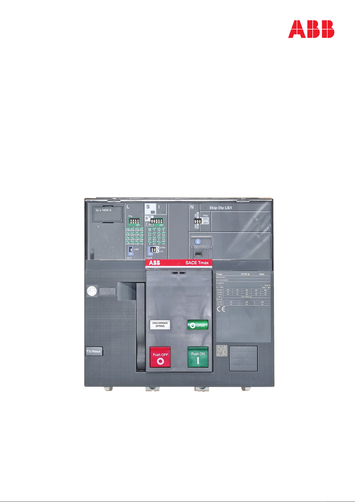
ABB TMAX XT XT7M Installation instructions

—
INSTRUCTION HANDBOOK
1SDH002302A1001 - ECN000285442
TMAX XT XT7M
Disassembly instructions


3
Disassembly instructiontmaX Xt Xt7m
1. SCOPE
Scope of this document is to illustrate the step-by-step disassembly process of ABB SACE Tmax XT
XT7M moulded case circuit breaker equipped with an electronic trip unit (type Ekip DIP LS/I).
Document is focused on Tmax XT XT7M 3p IEC version, anyway it allows to cover other versions of
Tmax XT XT7M circuit breaker with just few slight differences to be taken into account.
Gloves Glasses Safety shoes Protective clothes
4. TOOLS
Disassembly operations require the use of tools (e.g. screwdriver, torx key, pliers, …); tools to be used
are specified inside each phase of the disassembly process (see Chapter 6).
3. PERSONAL PROTECTIVE EQUIMENT (PPE)
When performing disassembly, following safety Personal Protective Equipment (PPE) must be worn:
2. SAFETY NOTES
Before proceeding with any disassembly operation, it’s mandatory to put the circuit breaker in open
position and make sure that the springs of the operating mechanism are discharged.
Disassembly operations of circuit breakers must be performed by qualified and skilled personnel in
the electrical field (IEV 195-04-01: person with relevant education and experience to enable him or her
to perceive risks and to avoid hazards which electricity can create) and having a detailed knowledge of
circuit breakers.
Disassembly activites must be performed in an ergonomic workspace able to ensure protection of per-
sons demanded to perform disassembly activities.
Applicable national legislation and international standards in force at the time of disassembly of circuit
breakers must be taken into account in addition to prescriptions illustrated in this document.
ABB declines any responsibility for injury to people or damage to property resulting from a failure to
comply with the instructions set out in this document and with any applicable safety standard.

4
INSTRUCTION HANDBOOK
If disassembled parts require a separate treatment a specific indication is provided inside each phase
with reason why for the separate treatment (see Chapter 6).
Description Position inside circuit breaker Quantity
Cap kits In correspondence of circuit breaker connection terminals
Lever In the T.U. reset group
Lever support In the T.U. reset group
Support Mounted on the upper part of the circuit breaker
Cables protection Mounted on the back part of the trip unit
Rating plug case Mounted on the front of the trip unit
Rating plug printed circuit board In the rating plug case
Backplane Mounted on the back part of the trip unit
Trip unit case On the trip unit
Trip unit back cover On the trip unit
Trip unit printed circuit board In the trip unit
Motor PCS support Mounted on the left part of the circuit breaker
Trip coil In the trip coil group
Trip coil group Mounted on the left part of the circuit breaker
MID Mounted on the right part of the circuit breaker
Wires cover Mounted on the left part of the circuit breaker
Wiring Mounted on the left part of the circuit breaker
RTC lever Mounted on the right side of the operating mechanism
Operating mechanism Mounted on the center of the circuit breaker
Unlocking shaft appendices Mounted on the pin of the operating mechanism
Springs charging lever Mounted on the left side of the operating mechanism
Protections Mounted on the upper case assembly
Fixed contacts protections Mounted on the fixed contacts
Covers Below the sensors
Sensors In the bottom part of the circuit breaker
Insulation protections On the moving contacts assembly
6. DISASSEMBLY PROCESS
Circuit breakers disassembly process is constituted by a sequence of operations to be performed on
products after their dismounting from original installation. For each phase following information are
provided:
applicable)
5. SEPARATE TREATMENT
Table below lists parts requiring a separate treatment adding information about part location inside
circuit breakers and related quantity.

5
Disassembly instructiontmaX Xt Xt7m
Tools
Allen key
Flat screwdriver
6.1 PHASE 1 – CAP KITS
1
By means of the cross screwdriver unscrew
the 2 screws fixing the terminal clamp to the
circuit breaker main structure.
4
By means of the flat screwdriver push the cap
kits in order to remove them from the circuit
breaker main structure.
3
By means of the allen key remove the screws
connected with the cap kits and after manually
remove the plates.
2
Manually remove the terminal clamp.
Actions to be performed
8mm
Cross screwdriver

6
INSTRUCTION HANDBOOK
(Metal)
containing brominated flame
retardants)
Disassembled parts
5
By means of the flat screwdriver remove the
nuts mounted on the cap kits.

7
Disassembly instructiontmaX Xt Xt7m
6.2 PHASE 2 – CIRCUIT BREAKER FRONT COVER AND OPERATING
MECHANISM COVER
6
Manually push the trip unit transparent
protection as indicated by the arrow and
remove it.
8
By means of the cross screwdriver unscrew the
2 screws located in the lower part of the circuit
breaker fixing the circuit breaker front cover to
the circuit breaker main structure.
7
Lift the springs charging lever and by means
of the cross screwdriver unscrew the screw
located below the springs charging lever fixing
the circuit breaker cover to the circuit breaker
main structure.
9
Manually lift the circuit breaker front cover to
complete the removal.
Actions to be performed
Tools
Torx key
No. 8
Cross screwdriver
Flat screwdriver

8
INSTRUCTION HANDBOOK
10
By means of the cross screwdriver unscrew the
screw fixing the T.U. reset group to the circuit
breaker front cover.
11
Manually lift the T.U. reset group and complete
the removal.
12
By means of the flat screwdriver unhook the
reset lever from the lever support of the T.U.
reset group.
13
Manually separate the lever support and the
lever.

9
Disassembly instructiontmaX Xt Xt7m
14
Manually remove the spring from the lever.
15
Manually remove the reset spring from the
lever support.
16
By means of the tork key remove the screw
fixing the operation counter cap to the circuit
breaker front cover and after manually remove
the operation counter cap.
17
By means of the tork key remove the 2 screws
fixing the front cap to the circuit breaker front
cover and after manually remove the front cap.

10
INSTRUCTION HANDBOOK
18
By means the cross screwdriver unscrew
the 2 screws located in the lower part of
the operating mechanism cover fixing the
operating mechanism cover to the main
structure of the circuit-breaker.
19
By means the cross screwdriver unscrew the
screw located on the right of the operating
mechanism cover fixing the operating
mechanism cover to the main structure of the
circuit breaker and manually complete the
removal of the operating mechanism cover.
containing brominated flame retardants)
(Thermoplastics containing brominated flame
retardants)
Disassembled parts

11
Disassembly instructiontmaX Xt Xt7m
Tools
Torx key
Cutter
Pliers
Flat screwdriver
6.3 PHASE 3 – TRIP UNIT
20
By means of a cross screwdriver unscrew the 2
screws fixing the support to the circuit breaker
main structure.
23
By means of the cross screwdriver unscrew the
2 screws located over the trip unit fixing the
trip unit to the circuit breaker main structure.
25
By means of the flat screwdriver disconnect
the connector from the trip unit and after
manually complete the removal of the trip unit.
22
By means of the cross screwdriver unscrew
the 2 screws located in the bottom part of the
trip unit and fixing the trip unit to the circuit
breaker main structure.
24
Manually push the cables protection as
indicated by the arrow and remove it.
21
Manually remove the support.
Actions to be performed
No. 8
Cross screwdriver

12
INSTRUCTION HANDBOOK
26
By means of the flat screwdriver remove the
rating plug from the trip unit.
31
By means of the torx key (size 8) unscrew the 2
screws fixing the backplane to the trip unit and
after manually remove the backplane.
28
Let the rating plug printed circuit board
mounted inside the rating plug let fall by
gravity.
29
By means of the cutter start removing the label
located on the front of the rating plug case and
manually complete the operation.
30
By means of the cutter start removing the
label located on the front of the trip unit and
manually complete the operation.
27
By means of the flat screwdriver open the
rating plug case.

13
Disassembly instructiontmaX Xt Xt7m
32
By means of the torx key (size 8) uncrew the 4
screws fixing the trip unit case to the trip unit
base.
33
By means of the flat screwdriver separate the
trip unit case from the trip unit back cover.
34
By means of the cutter start removing the
trip unit Data Matrix label located on the trip
unit back cover and by means of the pliers
complete the operation.
35
Manually remove the printed circuit board from
the trip unit back cover.

14
INSTRUCTION HANDBOOK
36
By means of the pliers remove the “i TEST”
pushbutton.
containing brominated flame retardants)
(Thermoplastics containing brominated flame retardants)
circuit board)
(Thermoplastics containing brominated flame retardants)
circuit board)
Disassembled parts

15
Disassembly instructiontmaX Xt Xt7m
Tools
Torx key
Flat screwdriver
6.4 PHASE 4 – ASSEMBLIES ON CIRCUIT BREAKER LEFT SIDE
Actions to be performed
No. 8
Cross screwdriver 37
By means of the cross screwdriver unscrew the
2 screws fixing the motor PCS support to the
circuit breaker main structure.
38
Manually remove the motor PCS support from
the circuit breaker main structure.
39
By means of the torx key unscrew the screw
fixing the PCS cover to motor PCS support.
40
Manually separate the PCS cover and the
motor PCS support.

16
INSTRUCTION HANDBOOK
41
By means of the cross screwdriver unscrew the
3 screws fixing the trip coil group to the circuit
breaker main structure.
42
By means of the flat screwdriver unhook the
connector from the trip coil group.
43
By means of the flat screwdriver lift the trip
coil group.
45
By means of the cross screwdriver unscrew the
screw fixing the lower plate to the trip coil.
44
Manually remove the trip coil group.
46
Manually push the lower plate as indicateted
by the arrow in order to complete the removal.

17
Disassembly instructiontmaX Xt Xt7m
47
By means of the flat screwdriver push out from
the trip coil group the trip coil.
containing brominated flame retardants)
Disassembled parts

18
INSTRUCTION HANDBOOK
Tools
Torx key
Allen key
Flat screwdriver
6.5 PHASE 5 – ASSEMBLIES MOUNTED ON CIRCUIT BREAKER
RIGHT SIDE
Actions to be performed
No. 15
Cross screwdriver
48
By means of the torx key unscrew the screw
fixing the support key block over the MID to
the operating mechanism.
49
By means of the allen key unscrew the 2 screws
fixing the support key block over the MID to
the operating mechanism.
50
Manually remove the support key block.
51
Manually remove the key block holder located
under the key block holder.
2.5mm

19
Disassembly instructiontmaX Xt Xt7m
52
Manually lift and remove the shunt opening
release plug.
53
By means of the cross screwdriver unscrew the
4 screws fixing the MID to the circuit breaker
main structure.
54
By means of the flat screwdriver remove the
benzing mounted on the lever present on the
right side of the operating mechanism.
55
Manually remove the lever pulling it as
indicated by the arrow.
56
Manually remove the MID.
57
Manually remove the auxiliary contacts lever
mounted on the MID.

20
INSTRUCTION HANDBOOK
58
By means of the cross screwdriver unscrew
the screw fixing the wires cover to the circuit
breaker main structure.
59
Manually remove the wires cover and the
wiring.
(Thermoplastics containing brominated flame
retardants)
(Thermoplastics containing brominated flame
retardants)
Disassembled parts
Table of contents
Other ABB Industrial Electrical manuals

ABB
ABB Zenith ZT30 User manual

ABB
ABB AF400 User manual

ABB
ABB Tmax XT XT3 Installation instructions

ABB
ABB MSOX User manual

ABB
ABB EBS852 User manual

ABB
ABB ILTS-E Series User manual

ABB
ABB Emax VF Quick guide

ABB
ABB TMAX XT XT6 ELECTRONIC Installation instructions

ABB
ABB UCC Series User manual

ABB
ABB Type A Operating and maintenance manual

ABB
ABB PQFS Manual

ABB
ABB TMAX XT XT2 THERMOMAGNETIC Installation instructions

ABB
ABB Ekip E-Hub User manual

ABB
ABB TA0107L User manual

ABB
ABB UZE User manual

ABB
ABB DCS800 User manual

ABB
ABB V-Contact VSC Series Quick guide

ABB
ABB MNS-SG User manual

ABB
ABB Relion 670 series User guide

ABB
ABB SACE Emax 2 User manual