ABB C571-AC User manual

Die hier beschriebenen Produkte wurden entwickelt, um als Teil einer Gesamt-
anlage oder Maschine sicherheitsgerichtete Funktionen zu übernehmen. Ein
komplettes sicherheitsgerichtetes System enthält in der Regel Sensoren, Aus-
werteeinheiten, Meldegeräte und Konzepte für sichere Abschaltungen. Es liegt
im Verantwortungsbereich des Herstellers einer Anlage oder Maschine die kor-
rekte Gesamtfunktion sicherzustellen. Die ABB AG, seine Niederlassungen und
Beteiligungsgesellschaften (im Folgenden “ABB”) ist nicht in der Lage, alle
Eigenschaften einer Gesamtanlage oder Maschine, die nicht durch ABB konzi-
piert wurde, zu garantieren.
ABB übernimmt auch keine Haftung für Empfehlungen, die durch die nachfol-
gende Beschreibung gegeben bzw. impliziert werden. Aufgrund der nachfolgen-
den Beschreibung können keine neuen, über die allgemeinen ABB-
Lieferbedingungen hinausgehenden, Garantie-, Gewährleistungs- oder Haf-
tungsansprüche abgeleitet werden.
Die Sicherheitskombination C571-AC können Sie in NOT-AUS-Einrichtungen
nach EN 418 und in Sicherheitsstromkreisen nach VDE 0113 Teil 1 (11.98) bzw.
EN 60 204-1 (12.97) verwenden, z. B. bei beweglichen Verdeckungen und Schutz-
türen. Je nach äußerer Beschaltung sind Sicherheitskategorie 3 und 4 nach
DIN EN 954-1 zu erreichen.
Beim Einsatz der Sicherheitskombination in der Betriebsart "Automatischer
Start" ist beim Ausschalten im Notfall (NOT-AUS) der automatische Wiederan-
lauf (gemäß EN 60 204-1, Abschnitt 9.2.5.4.2 und 10.8.3) durch die übergeord-
nete Steuerung zu verhindern.
Die Sicherheitskombination C571-AC besitzt zwei Freigabekreise (sichere
Kreise) als Schließerkreise. Die Anzahl der Freigabekreise können durch Hinzu-
schalten eines oder mehrerer Erweiterungsbausteine C579 ergänzt werden. Drei
LEDs zeigen den Betriebszustand und die Funktion an.
Beim Entriegeln der NOT-AUS-Taster bzw. der Grenztaster und beim Betätigen
des EIN-Tasters werden die interne Schaltung der Sicherheitskombination und
die externen Schütze auf korrekte Funktion überprüft.
Schließen Sie den NOT-AUS-Taster bzw. den Grenztaster an die Klemmen Y11,
12 und Y21, 22 an. Der EIN-Taster wird in Reihe mit den Öffnerkontakten der
externen Schütze (Rückführkreis) an die Klemmen Y33, 34 angeschlossen.
Halten Sie die vorgeschriebene Absicherung unbedingt ein,
nur so ist ein sicheres Abschalten im Fehlerfall gewährleistet.
Weitere Daten und Bestellnummern für Zubehör siehe
Hauptkatalog Teil 1.
Warnung:
Gefährliche elektrische Spannung!
Kann zu elektrischem Schlag
und Verbrennungen führen.
Vor Beginn der Arbeiten Anlage
und Gerät spannungsfrei schalten.
Wichtiger Hinweis
Anwendungsbereiche
Funktionsbeschreibung und Anschlusshinweise
Klemmen-
belegung
Betriebs-
spannung
A1
A2
L
N
Sensoren Y11, 12
Y21, 22
Y33, 34
Kanal 1 NOT-AUS bzw.
Positionsschalter
Kanal 2 NOT-AUS bzw.
Positionsschalter
EIN-Taster, Rückführkreis
Ausgänge 13, 14
23, 24
Freigabekreis 1 (Schließer)
Freigabekreis 2 (Schließer)
Leitungslängen bei 2 x 1,5 mm2
150 nF/km
max. 1000 m (Gesamtleitungslänge
für Sensorik)
Bilder Bild I: Maßbild (Maße in mm)
Bild II: Montage / Cage Clamp
Bild III: Innenbeschaltung: ¿ Netzteil, À Steuerlogik,
Á Channel 1, Â Channel 2
Bild IV: Zweikanaliger Autostart für Schutztürüberwachung,
Sicherheitskategorie 3 und 4 nach EN 954-1
Bild V: NOT-AUS zweikanalig mit zusätzlichem EIN-Taster,
Sicherheitskategorie 3 und 4 nach EN 954-1
Bild VI: NOT-AUS einkanalig mit zusätzlichem EIN-Taster,
Sicherheitskategorie 2 nach EN 954-1
Betriebszustände
LEDs Betrieb
POWER Channel 1 Channel 2 Netz NOT-AUS EIN Freigabe-
kreise
ein nicht betätigt betätigt geschlos-
sen
betätigt nicht betätigt offen
nicht betätigt nicht betätigt offen
Fehler
•Relais verschweißt
•Motorschütz verschweißt
•Defekt in Elektronik
offen
Quer- bzw. Erdschluss in NOT-AUS-
Kreis
Fehler-
beseitigung
1. Schalten Sie die Versorgungsspannung ab.
2. Beseitigen Sie den Fehler bzw. tauschen Sie das Gerät aus.
3. Schalten Sie die Versorgungsspannung wieder ein.
Technische Daten
Zulässige Umgebungstemperatur Tu
Betrieb/Lagerung -25 ... +60 °C/-40 ... +80 °C
Schutzart nach EN 60 529 IP 40, IP 20 an den Klemmen
Bemessungsisolationsspannung Ui300 V
Bemessungsstoßspannungsfestigkeit Uimp 4 kV
Bemessungssteuerspeisespannung UsC571-AC-115 115 V AC
C571-AC-230 230 V AC
Bemessungsleistung 1,5 W
Arbeitsbereich 0,85 ... 1,1 x Us
Schockfestigkeit Halbsinus nach IEC 60068 8 g/10 ms
Gewicht 0,250 kg
Wiederbereitschaftszeit bei NOT-AUS min. 120 ms
Rückfallzeit bei NOT-AUS max. 100 ms
Ansprechzeit max. 500 ms
Gebrauchs-
kategorie
nach DIN VDE 0660
Teil 200, IEC 60947-5-1
Bemessungs-
betriebsspannung UeBemessungsbetriebsstrom Ie
bei Belastung aller Freigabekreise
AC-15 230 V 6 A
DC-13 24 V 6 A
115 V 0,2 A
230 V 0,1 A
Dauerstrom Ith 6 A
Kurzschlussschutz
für Freigabekreis
Sicherungseinsätze DIAZED
Betriebsklasse gL(gG) 6 A
flink 10 A
4NEB 926 0224-10 1
Sicherheitskombination C571-AC
DIN EN 60 439 Teil 1, VDE 0660 Teil 500
Betriebsanleitung Bestell-Nr.: 1SAC 105 198 S4001 Deutsch
9260224.book Seite 1 Montag, 3. Juni 2002 11:04 11

The products described herein are designed to be components of a customized
machinery safety-oriented control system. A complete safety-oriented system
may include safety sensors, evaluators, actuators and signaling components. It
is the responsibility of each company to conduct its own evalution of the effecti-
veness of the safety system by trained individuals. ABB AG, its subsidiaries and
affiliates (collectively "ABB") are not in a position to evaluate all of the charac-
teristics of a given machine or product or machine not designed by ABB.
ABB accepts no liability for any recommendation that may be implied or stated
herein. The warranty contained in the contract of sale by ABB is the sole war-
ranty of ABB. Any statements contained herein do not create new warranties or
modify existing ones.
You can use the safety combination C571-AC in EMERGENCY STOP devices as
per EN 418 and in safety circuits as per VDE 0113 Part 1 (11.98) and/or
EN 60 204-1 (12.97), e.g. with movable covers and guard doors. Depending on
the external connections, safety categories 3 and 4 as per DIN EN 954-1 are
achievable.
When the safety combination is used in "Automatischer Start" mode, automatic
restarting (as per EN 60 204-1, Sections 9.2.5.4.2 and 10.8.3) must be prevented
by the higher-level control system in the event of EMERGENCY STOP.
The Safety combination C571-AC has two release (safe) circuits which are confi-
gured as NO circuits. The number of release circuits can be increased by adding
one or more C579 extension modules. Three LEDs indicate the operating state
and function.
When the EMERGENCY STOP button or the limit switch is unlocked and when
the ON button is pressed, the internal circuits of the safety combination and the
external contactors are checked for proper functioning.
Connect the EMERGENCY STOP button or the limit switch to terminals Y11, 12
and Y21, 22. The ON button is connected in series with the NC contacts of the
external contactor (feedback circuit) at terminals Y33, 34.
Be sure to fit the specified fuses. Otherwise safe interruption
in the event of a fault cannot be guaranteed.
For further data and accessories see Main catalog, part1.
WARNING:
HAZARDOUS VOLTAGE
CAN CAUSE ELECTRICAL SHOCK
AND BURNS.
DISCONNECT POWER BEFORE PROCEEDING
WITH ANY WORK ON THIS EQUIPMENT.
IMPORTANT NOTICE
Application
Functions and connections
Terminal
assignments
Operating
voltage
A1
A2
L
N
Sensors Y11, 12
Y21, 22
Y33, 34
Channel 1 EMERGENCY STOP or limit switch
Channel 2 EMERGENCY STOP or limit switch
ON button, feedback circuit
Outputs 13, 14
23, 24
Release circuit 1 (NO)
Release circuit 2 (NO)
Cable lengths for 2 x 1.5 mm2
150 nF/km
max. 1000 m (total cable length for
sensors)
Figures Fig. I: Dimension drawings (dimensions in mm)
Fig. II: Installation / Cage Clamp
Fig. III: Internal circuit: ¿ power pack, Àcontrol logic,
Á Channel 1, Â Channel 2
Fig. IV: Two-channel autostart for contactor monitoring,
safety category 3 and 4 per EN 954-1
Figures Fig. V: Two-channel EMERGENCY STOP with additional ON
button, safety category 3 and 4 per EN 954-1
Fig. VI: Single-channel EMERGENCY STOP with additional
ON button, safety category 2 per EN 954-1
Operating states
LEDs Operation
POWER Channel 1 Channel 2 PS EMERGENCY
STOP ON Release
circuits
ON not activated activated closed
activated not activated open
not activated not activated open
Faults
•Relay fusion-welded
•Motor contactor fusion-welded
•Defect in electronics
open
Cross or ground faults in
EMERGENCY STOP circuit
Fault
clearance
1. Switch supply voltage off.
2. Clear fault or replace device.
3. Switch supply voltage back on.
Technical data
Permissible ambient temperature Tu
Operation/storage -25 to +60°C/-40 to +80°C
Degree of protection to EN 60 529 IP 40, IP 20 at terminals
Rated insulation voltage Ui300 V
Rated impulse withstand voltage Uimp 4 kV
Rated control supply voltage UsC571-AC-115 115 V AC
C571-AC-230 230 V AC
Rated power 1.5 W
Operating range 0.85 to 1.1 x Us
Shock resistance (half-sine) as per IEC 60068 8 g/10 ms
Weight 0.250 kg
Recovery time after EMERGENCY STOP minimum 120 ms
Release time after EMERGENCY STOP max. 100 ms
Response time max. 500 ms
Utilization
category
as per DIN VDE 0660
Part 200, IEC 60947-5-1
Rated operational
voltage UeRated operational current Ie
with all release circuits loaded
AC-15 230 V 6 A
DC-13 24 V 6 A
115 V 0,2 A
230 V 0,1 A
Continuous current Ith 6A
Short-circuit protection
for release circuit Fuse links DIAZED
Duty class gL(gG) 6 A
quick response 10 A
2
Safety Combination C571-AC
DIN EN 60 439 Part 1, VDE 0660 Part 500
Instructions Order No.: 1SAC 105 198 S4001 English
9260224.book Seite 1 Montag, 3. Juni 2002 11:04 11

Les produits décrits dans cette notice ont étédéveloppés pour assurer des
fonctions de sécuritéen tant qu’éléments d’une installation complète ou d’une
machine. Un système de sécuritécomplet comporte en règle générale des cap-
teurs, des unités de traitement, des appareils de signalisation et des concepts
de mise en sécurité. Il incombe au concepteur/constructeur de l’installation ou
de la machine d’assurer le fonctionnement correct de l’ensemble. ABB AG, ses
succursales et ses participations (désignées ci-après par “ABB”) ne sont pas en
mesure de garantir toutes les propriétés d’une installation complète ou d’une
machine qui n’a pas étéconçue par ABB.
ABB dégage toute responsabilitépour les recommandations données dans la
description ci-dessous ou qui peuvent en être déduites. La description ci-des-
sous ne peut pas être invoquée pour faire valoir des revendications au titre de la
garantie ou de la responsabilité, qui dépasseraient les clauses des conditions
générales de livraison de ABB.
Le module de sécuritéC571-AC peuvent être utilisés dans les dispositifs
d'ARRET d'URGENCE selon EN 418 et dans les circuits de sécuritéselon
EN 60 204-1 (11.98) ou VDE 0113 P. 1 (12.97), par exemple pour barrages mobiles
et portes de sécurité. Suivant le montage externe, on peut obtenir la catégorie
de sécurité3 ou 4 selon DIN EN 954-1.
Lorsque le module de sécuritéest utiliséen mode "Démarrage automatique", le
redémarrage automatique (conformément àEN 60 204-1, paragraphes 9.2.5.4.2
et 10.8.3) àla suite d’une coupure d’urgence (ARRET D’URGENCE) doit être
empêchéau niveau du système de commande de niveau supérieur.
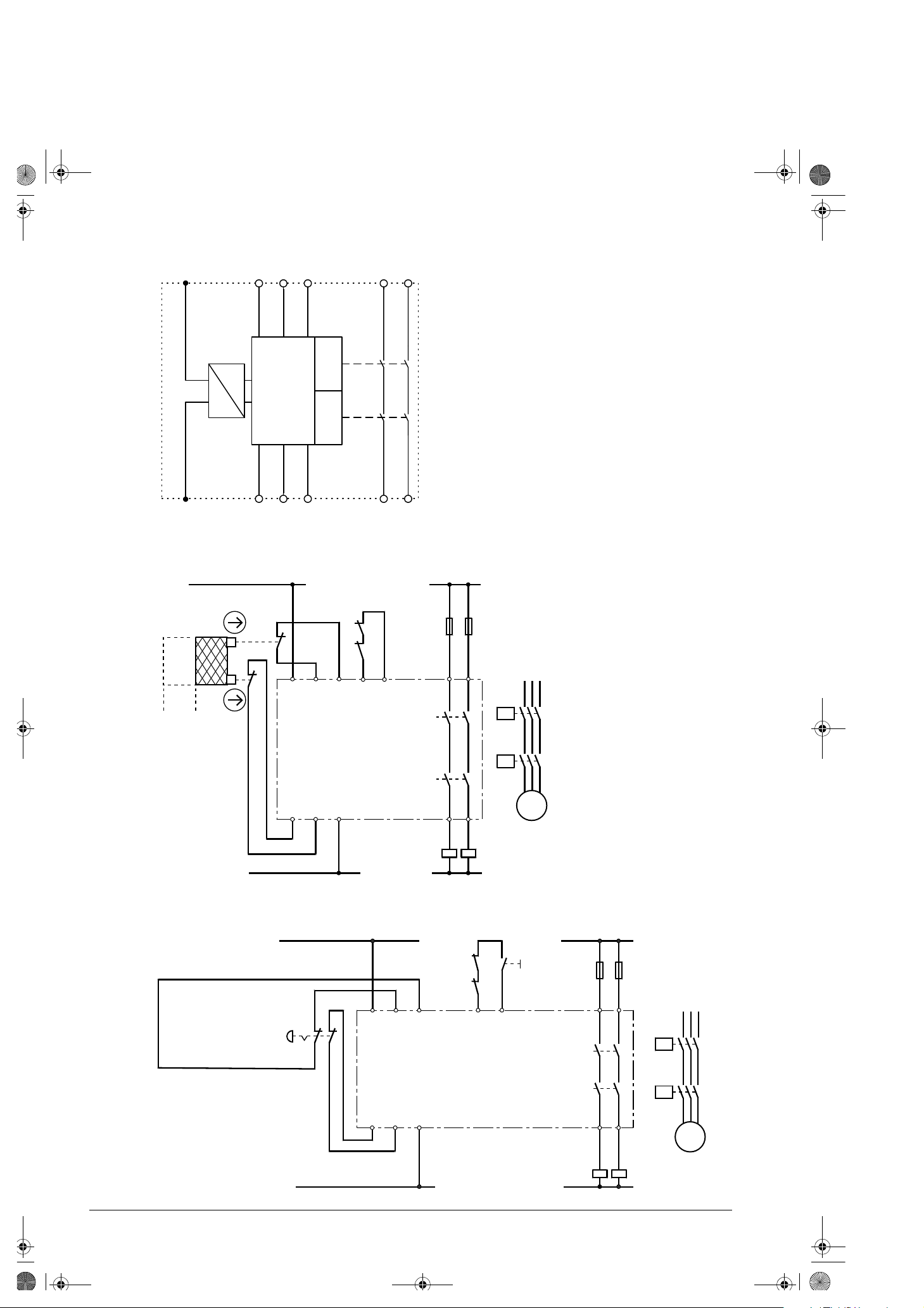
Le module de sécuritéC571-AC comporte deux circuits de validation (circuits de
sécurité) du type normalement ouvert. Le nombre de circuits de validation peut
être augmentépar ajout d'un ou de plusieurs modules d'extension C579. L'état
de fonctionnement est signalépar trois LED.
Au déverrouillage du bouton d'ARRET D'URGENCE, au relâchement des interrup-
teurs de position et àl'actionnement du bouton MARCHE, le montage interne du
module de sécuritéet les contacteurs externes subissent un test fonctionnel.
Raccordez le bouton d'ARRET D'URGENCE et les interrupteurs de position aux bornes
Y11, 12 et Y21, 22. Le bouton MARCHE est branchéen série avec les contacts NF
du contacteur externe (circuit de retour) aux bornes Y33, 34.
La coupure sûre en cas de défaut n’est garantie que lorsque la
protection contre les courts-circuits est réalisée de la manière
prescrite.
Pour de plus amples informations et pour les accessoires, voir Catalogue,
partie 1.
Attention !
Tension dangereuse !
Risque d’électrocution et de brûlure.
Isoler cet appareil du réseau avant d’y
intervenir pour travaux.
Remarque importante
Domaines d’utilisation
Principe de fonctionnement et remarques concernant le raccordement
Affectation des
bornes
Tension
d’emploi
A1
A2
L
N
Capteurs Y11, 12
Y21, 22
Y33, 34
canal 1 AU ou interrupt.pos.
canal 2 AU ou interrupt.pos.
bouton MARCHE, boucle de retour
Sorties 13, 14
23, 24
circuit de validation 1 (NO)
circuit de validation 2 (NO)
Longueur de
câbles
pour 2 x 1,5 mm2
150 nF/km
max. 1000 m (longueur de câble totale
pour capteurs)
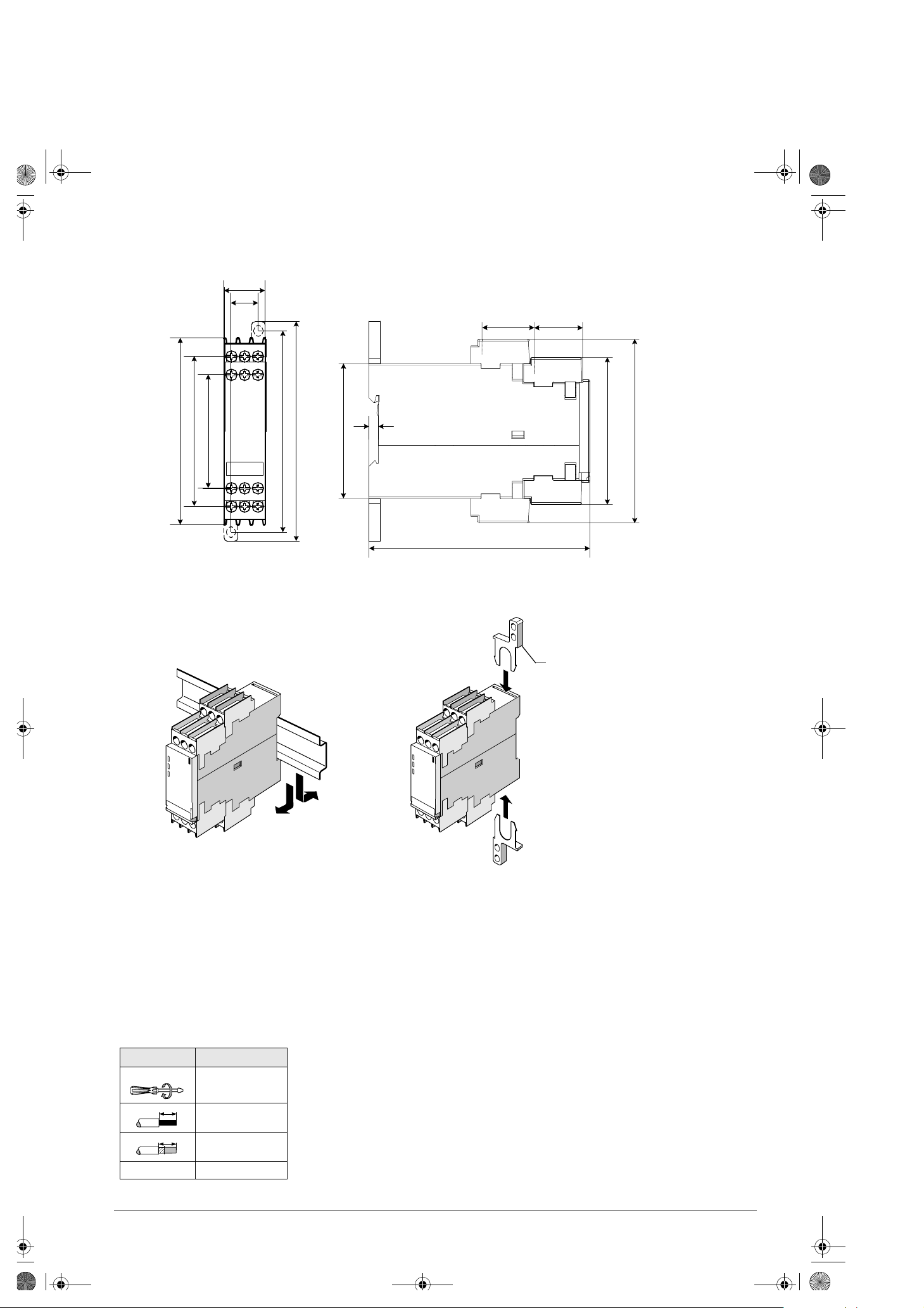
Figures Fig. I : Encombrements (cotes en mm)
Fig. II : Montage / borne àcage
Fig. III : Montage interne : ¿ bloc secteur,
Àlogique de commande, Á canal 1, Â canal 2
Fig. IV: Démarrage autom. bicanal pour surveillance de porte de
sécurité, catégorie de sécurité3 et 4 selon EN 954-1
Figures Fig. V: ARRET D’URGENCE bicanal avec bouton MARCHE sup-
plémentaire, catégorie de sécurité3 et 4 selon EN 954-1
Fig. VI: ARRET D’URGENCE monocanal avec bouton MARCHE
supplémentaire, catégorie de sécurité2 selon EN 954-1
Etats de fonctionnement
LED Service
POWER Canal 1 Canal 2 Ré-
seau ARRET
D’URGENCE MARCHE Circuits
de valid.
appli-
qué
libéréactionnéfermés
actionnélibéréouverts
libérélibéréouverts
Défauts
•Relais collé
•Contacteur mot. collé
•Défaut dans électronique
ouverts
Les courts-circuits et défauts àla
terre dans le circuit AU
Elimination du
défaut
1. Coupez la tension d’alimentation.
2. Eliminez le défaut ou remplacer l'appareil.
3. Appliquez ànouveau la tension d'alimentation.
Caractéristiques techniques
Température ambiante admissible Tu
en fonctionnement/au stockage -25 à+60 °C/-40 à+80 °C
Degréde protection selon EN 60 529 IP 40, IP 20 aux bornes
Tension assignée d’isolement Ui300 V
Tension assignée de tenue aux chocs Uimp 4 kV
Tension assignée d’alimentation de commande UsC571-AC-115 115 V AC
C571-AC-230 230 V AC
Puissance assignée1,5W
Plage de fonctionnement 0,85 à1,1 x Us
Tenue aux chocs 1/2 sinus selon CEI 60068 8 g/10 ms
Poids 0,250 kg
Temps de récupération sur ARRET D'URGENCE minimum 120 ms
Durée de retombée sur ARRET D'URGENCE max. 100 ms
Temps de réponse max. 500 ms
Catégorie
d’emploi
selon DIN VDE 0660
partie 200, CEI 60947-5-1
Tension assignée
d’emploi UeCourant assignéd’emploi Ie
tous circuits de validation chargés
AC-15 230 V 6 A
DC-13 24 V 6 A
115 V 0,2 A
230 V 0,1 A
Courant de service continu Ith 6 A
Protection contre les courts-circuits
du circuit de validation
Cartouches fusibles DIAZED
Classe de service gL(gG) 6 A
rapide 10 A
3
Module de sécuritéC571-AC
DIN EN 60 439 partie 1, VDE 0660 partie 500
Instructions de service Node référence : 1SAC 105 198 S4001 Français
9260224.book Seite 1 Montag, 3. Juni 2002 11:04 11

Los productos aquídescritos han sido desarrollados para ejecutar funciones de
seguridad formando parte de una instalación completa o máquina. Un sistema
completo de seguridad incluye por regla general sensores, unidades de evalua-
ción, aparatos de señalización y filosofías que aseguran desconexiones seguras.
Por ello es responsabilidad del fabricante de una instalación o máquina asegurar
el funcionamiento correcto del conjunto. La ABB AG, sus filiales y sociedades
participadas (en lo sucesivo “ABB”) no están en condiciones de garantizar las
propiedades de una instalación completa o máquina que no haya sido concebida
por ABB.
ABB tampoco se hace responsable de recomendaciones que emanen implícita o
explícitamente de la descripción siguiente. De la descripción siguiente no es
posible reclamar ningún tipo de prestaciones de garantía o responsabilidad civil
que excedan en las enunciadas en las Condiciones Generales de Suministro de
ABB.
La combinación de seguridad C571-AC pueden usarse como dispositivos de
PARO DE EMERGENCIA según EN 418 y en circuitos de seguridad según VDE
0113 parte 1 (11.98) y EN 60 204-1 (12.97), p. ej. en tapas móviles y puertas de
protección. Dependiendo del conexionado externo deberán alcanzarse las cate-
gorías de protección 3 y 4 según DIN EN 954-1.
Si la combinación de seguridad se utiliza en el modo "arranque automático", en
caso de desconexión de emergencia (parada de emergencia) el mandocontrol
superior deberáevitar el rearranque automático (conforme a EN 60 204-1, apts.
9.2.5.4.2 y 10.8.3).
La combinación de seguridad C571-AC consta de dos circuitos de habilitación
(seguros) normalmente abiertos. El número de circuitos puede aumentar conec-
tando uno o varios módulos de ampliación C579. Tres LEDs señalizan el estado
de servicio y la función.
Al rearmar el pulsador PARO DE EMERGENCIA o interruptores límite y al pulsar
el pulsador ON se verifica si el conexionado interno de la combinación de segu-
ridad y los contactores externos funcionan correctamente.
Conectar el pulsador PARO DE EMERGENCIA o interruptor límite a los bornes
Y11, 12 y Y21, 22. El pulsador ON se conectan en serie con los contactos NC de
los contactores externos (circuito de retorno) en los bornes Y33, 34.
Respetar imprescindiblemente la protección prescrita; sólo así
estágarantizada la desconexión segura en caso de defecto.
Para más datos y el Nºde referencia para accesorios, v. Catálogo, parte 1.
Precaución:
¡Tensión peligrosa!
Puede causar choque eléctrico y quemaduras.
Desconectar la alimentación antes de efectuar
trabajo alguno en este equipo.
Nota importante
Aplicaciones
Descripción funcional e indicaciones de conexión
Ocupación de
bornes
Tensión de
servicio A1
A2 L
N
Sensores Y11, 12
Y21, 22
Y33, 34
Canal 1 P. EMERG. o interruptor límite
Canal 2 P. EMERG. o interruptor límite
Pulsador ON, circuito de retorno
Salidas 13, 14
23, 24 C. habilitación 1 (NA)
C. habilitación 2 (NA)
Long. de
cable
para 2 x 1,5 mm2
150 nF/km
máx. 1000 m (longitud total para sensores)
Figuras Fig. I: Croquis acotados (dimensiones en mm)
Fig. II: Montaje / Cage Clamp
Fig. III: Conexionado interno: ¿ Alimentación,
ÀLógica de mando, Á Canal 1, Â Canal 2
Figuras Fig. IV: Autoarranque, en 2 canales, para vigilancia de puerta de
protección, categorías de protección 3 y 4 segúnEN 954-1
Fig. V: PARO DE EMERGENCIA, 2 canales, con pulsador ON
categorías de protección 3 y 4 segúnEN 954-1
Fig. VI: PARO DE EMERGENCIA, 1 canal, con pulsador ON
categoría de protección 2 segúnEN 954-1
Estados operativos
LEDs Operación
POWER Canal 1 Canal 2 Red PARO EMER-
GENCIA ON Circuitos
de habil.
ON no accionado accionado cerrados
accionado no accionado abiertos
no accionado no accionado abiertos
Fallo
•Relésoldado
•Contactor del motor soldado
•Defecto en la parte electrónica
abierto
Contacto a tierra o transversal en el
circuito PARO EMERGENCIA
Remedio 1. Desconectar la alimentación.
2. Reparar el desperfecto o sustituir el aparato.
3. Conectar nuevamente la alimentación.
Datos técnicos
Temperatura ambiente admisible Tu
Operación/Almacenamiento -25 a +60 °C/-40 a +80 °C
Categoría de protección según EN 60 529 IP 40, IP 20 en los bornes
Tensión asignada de aislamiento Ui300 V
Tensión de choque asignada Uimp 4 kV
Tensión asignada de alimentación
de mando Up
C571-AC-115 115 V AC
C571-AC-230 230 V AC
Potencia asignada 1,5 W
Campo de trabajo 0,85 a 1,1 x Up
Resist. a choques onda semisenoidal
según IEC 60068 8 g/10 ms
Peso 0,250 kg
Tiempo de redisponibilidad tras PARO DE EMERGENCIA min. 120 ms
Tiempo de caída tras PARO DE EMERGENCIA máx. 100 ms
Tiempo de respuesta máx. 500 ms
Categoría de
aplicación
según DIN VDE 0660
parte 200, IEC 60947-5-1
Tensión asignada
de servicio UeIntensidad asig. de servicio Ie
con tod. los circ. de habil. cargados
AC-15 230 V 6 A
DC-13 24 V 6 A
115 V 0,2 A
230 V 0,1 A
Int. permanente Ith 6 A
Protección contra cortos
en circuito de habilitación
Cartuchos fusibles DIAZED
Clase de servicio gL(gG) 6 A
rápido 10 A
4
Combinación de seguridad C571-AC
DIN EN 60 439 parte 1, VDE 0660 parte 500
Instrucciones de servicio Nºde pedido: 1SAC 105 198 S4001 Español
9260224.book Seite 1 Montag, 3. Juni 2002 11:04 11

I prodotti qui descritti sono stati concepiti per svolgere funzioni rilevanti per la
sicurezza in interi impianti. Un sistema di sicurezza completo prevede nor-
malmente sensori, disposititvi di segnalazione, apparecchiature e unitàdi valu-
tazione e dispositivi per disinserzioni sicure. Ècompito del costruttore di
macchine garantire il funzionamento sicuro dell’im-pianto o della macchina. La
ABB AG, le sue filiali e consociate (qui di seguito "ABB") non sono in grado di
garantire tutte le caratteristiche di un impianto o una macchina non ideati da
ABB.
ABB declina ogni responsabilitàper raccomandazioni contenute nella presente
descrizione. Non èpossibile in base alla presente documentazione revendicare
diritti di garanzia e/o responsabilitàche vadano oltre quanto contenuto nelle
condizioni generali di vendita e fornitura.
I dispositivi di sicurezza C571-AC possono essere utilizzati nei dispositivi d’emer-
genza secondo EN 418 e nei circuiti di sicurezza secondo VDE 0113 Parte 1 (11.98)
ed EN 60 204-1 (12.97), per esempio per carter di protezione e protezione portella.
In funzione del circuito esterno èpossibile raggiungere categoria di sicurezza 3 e 4
secondo DIN EN 954-1.
Utilizzando la combinazione di sicurezza nel modo operativo "Avvio automatico"
ènecessario evitare il riavvio automatico (sec. EN 60 204-1, sez. 9.2.5.4.2 e
10.8.3) dal controllore sovraordinato in caso di disinserzione per emergenza
(EMERGENZA).
I dispositivi di sicurezza C571-AC possiedono due circuiti di sgancio (circuiti di
sicurezza) come circuiti di chiusura. Il numero dei circuiti di sgancio possono
essere completati con l’aggiunta di uno o piùmoduli d’ampliamento C579. Tre
LED segnalano lo stato di esercizio e la funzione.
Allo sblocco del tasto d’emergenza o del finecorsa e al comando del tasto di chi-
usura viene verificato il corretto funzionamento del circuito interno del disposi-
tivo di sicurezza e dei contattori esterni.
Collegare il tasto d’emergenza ed il finecorsa ai morsetti Y11, 12 e Y21, 22. Il
tasto d’inserzione viene collegato in serie ai contatti NC del contattore esterno
(circuito di recupero) sui morsetti Y33, 34.
Rispettare assolutamente le protezioni prescritte in modo che
sia garantito un disinserimento sicuro in caso di guasto.
Per altri dati e per le sigle di ordinazione degli accessori vedere il
catalogo, Parte 1.
Attenzione:
Tensione elettrica pericolosa!
Rischio di shock elettrico e ustioni.
Prima di eseguire qualsiasi tipo di lavoro,
assicurarsi che l’apparecchio e l’impianto
siano scollegati.
Avviso importante
Campo d’impiego
Descrizione del funzionamento e indicazioni per il collegamento
Collegamento
dei morsetti
Tensione di
esercizio A1
A2 L
N
Sensori Y11, 12
Y21, 22
Y33, 34
Tasto emerg. o finecorsa canale 1
Tasto emerg. o finecorsa canale 2
Tasto di chiusura, circuito retroazione
Uscita 13, 14
23, 24 Circuito di sgancio 1 (in chiusura)
Circuito di sgancio 2 (in chiusura)
Lunghezza
conduttori
con 2 x 1,5 mm2
150 nF/km
max. 1000 m (lunghezza totale per
sensori)
Figure Fig. I: Dimensioni (in mm)
Fig. II: Montaggio / Cage Clamp
Fig. III: Circuito interno : ¿Parte di rete, ÀLogica di comando,
ÁCanale 1, ÂCanale 2
Fig. IV: Avvio automatico a due canali con sorveglianza
contattore, categoria di sicurezza 3 e 4 secondo EN 954-1
Figure Fig. V: EMERGENZA a due canali con tasto d’inserzione,
categoria di sicurezza 3 e 4 secondo EN 954-1
Fig. VI: EMERGENZA a un canale con tasto d’inserzione,
categoria di sicurezza 2 secondo EN 954-1
Stati d’esercizio
LEDs Funzionamento
POWER Canale 1 Canale 2 Rete Emerg. EIN (ON) Circuitodi
sgancio
ON non azionato azionato chiuso
azionato non azionato aperto
non azionato non azionato aperto
Errore
•Relèincollato
•Contattore motore incollato
•Difetto nell’elettronica
aperto
Guasto tra fasi o verso terra nel
circuito d'emergenza
Eliminazione del
guasto
1. Togliere la tensione di alimentazione.
2. Eliminare il guasto o sostituire l’apparecchio.
3. Ridare tensione.
Dati tecnici
Temperatura ambiente ammissibile Tu
di funzionamento/magazzinaggio -25 ... +60 °C/-40 ... +80 °C
Grado di protezione secondo EN 60 529 IP 40, IP 20 ai morsetti
Tensione nominale d’isolamento Ui300 V
Tensione nominale di tenuta ad impulso Uimp 4 kV
Tensione nominale di comando UsC571-AC-115 115 V AC
C571-AC-230 230 V AC
Potenza nominale 1,5 W
Campo di lavoro 0,85 ... 1,1 x Us
Resistenza agli urti secondo IEC 60068 8 g/10 ms
Peso 0,250 kg
Tempo di riarmo in caso di EMERGENZA min. 120 ms
Tempo di commutazione in caso di EMERGENZA max. 100 ms
Tempo di risposta max. 500 ms
Categoria di
utilizzazione
sec. DIN VDE 0660
parte 200, IEC 60947-5-1
Tensione nominale
d’impiego UeCorrente nominale d’impiego Ie
con carico su tutti i circuiti di sgancio
AC-15 230 V 6 A
DC-13 24 V 6 A
115 V 0,2 A
230 V 0,1 A
Corrente permanente Ith 6 A
Protezione da corto-circuito
per circuito di sgancio
Fusibili DIAZED
Classe d’esercizio gL(gG) 6 A
veloce 10 A
5
Dispositivo di sicurezza C571-AC
DIN EN 60 439 Parte 1, VDE 0660 Parte 500
Istruzioni di servizio No. di ordinaz.: 1SAC 105 198 S4001 Italiano
9260224.book Seite 1 Montag, 3. Juni 2002 11:04 11

De här beskrivna produkterna utvecklades, för att som del i en anläggning eller
maskin överta säkerhetsinriktade funktioner. Ett komplett säkerhetsinriktat
system innehåller som regel sensorer, utvärderingsenheter, signaldon och kon-
cept för säkra frånkopplingar. Det tillhör tillverkarens ansvarsområde att garan-
tera den korrekta totala funktionen hos en anläggning eller maskin. ABB AG,
dess dotterföretag och partnerfirmor (i det följande “ABB”) är inte i stånd att
garantera alla egenskaper hos en anläggning eller maskin, som inte koncipiera-
des av ABB.
ABB övertar heller inget ansvar för rekommendationer, som ges eller ingår i den
följande beskrivningen. Till följd av den följande beskrivningen kan inga nya
anspråk pågaranti eller ansvar härledas utöver ABB allmänna leveransvillkor.
Säkerhetskombinationen C571-AC kan användas i NÖDSTOPP-anordningar enligt
EN 418 och i säkerhetströmkretsar enligt VDE 0113 del 1 (11.98) resp.
EN 60 204-1 (12.97), t.ex. för rörliga kåpor och skyddsdörrar. Allt efter den yttre
kopplingen kan säkerhetskategori 3 och 4 enligt DIN EN 954-1 uppnås.
Vid användning av säkerhetskombinationen i driftsläget "Automatisk start"
skall vid frånkoppling i nödfall (NÖDSTOPP) den automatiska återstarten (enligt
EN 60 204-1, kap. 9.2.5.4.2 och 10.8.3) förhindras via den överordnade
styrningen.
Säkerhetskombinationen C571-AC har tvåfrigivningskretsar (säkra kretsar) som
slutarkretsar. Antalet frigivningskretsar kan kompletteras genom att koppla till
en eller flera utbyggnadskomponenter C579. Tre LEDs visar alltid driftstillstån-
det och funktionen.
Vid uppregling av NÖDSTOPP-knappen resp. gränsknappen och när TILL-knappen
trycks ner kontrolleras att den inre kopplingen i säkerhetskombinationen och de
externa kontaktorerna fungerar korrekt.
Anslut NÖDSTOPP-knappen resp. gränsknappen till uttagen Y11, 12 och Y21, 22.
TILL-knappen ansluts i serie med öppnarkontakterna till den externa kontaktorn
(återföringskrets) till uttagen Y33, 34.
Bara om föreskrivna säkringar används kan man räkna med att
fåpålitlig frånkoppling vid fel.
Ytterligare uppgifter och tillbehör se katalog, Teil 1.
Varning:
Farlig spänning!
Kan vålla elektriska stötar och brännskador.
Slåifrån strömmen innan något arbete utförs
pådenna utrustning.
Viktig information
Användningsområden
Funktionsbeskrivning och anslutningsanvisningar
Uttags-
beläggning
Drifts-
spänning A1
A2 L
N
Sensorer Y11, 12
Y21, 22
Y33, 34
Kanal 1 NÖDSTOPP resp. gränsknapp
Kanal 2 NÖDSTOPP resp. gränsknapp
TILL-knapp, återföringskrets
Utgångar 13, 14
23, 24 Frigivningskrets 1 (slutare)
Frigivningskrets 2 (slutare)
Ledningslängder för 2 x 1,5 mm2
150 nF/km
max. 1000 m (total ledningslängd
för sensorik)
Figurer Fig. I: Måttskisser (mått i mm)
Fig. II: Montering / Cage Clamp
Fig. III: Inre koppling: ¿ nätdel, Àstyrlogik,
Á channel 1, Â channel 2
Fig. IV: Tvåkanalig autostart för skyddsdörrsövervakning,
säkerhetskategori 3 och 4 enligt EN 954-1
Figurer Fig. V: NÖDSTOPP tvåkanaligt med extra TILL-knapp,
säkerhetskategori 3 och 4 enligt EN 954-1
Fig. VI: NÖDSTOPP enkanaligt med extra TILL-knapp,
säkerhetskategori 2 enligt EN 954-1
Driftstillstånd
LEDs Drift
POWER Channel 1 Channel 2 Nät NÖDSTOPP TILL Frigivn.-
kretsar
till ej intryckt intryckt stängd
intryckt ej intryckt öppen
ej intryckt ej intryckt öppen
Fel
•Relähopsmält
•Motorkontaktor hopsmält
•Defekt i elektroniken
öppen
Tvär- resp. jordfel i NÖDSTOPP-krets
Felens
åtgärdande
1. Koppla från försörjningsspänningen.
2. Åtgärda felet resp. byt ut instrumentet.
3. Koppla åter till försörjningsspänningen.
Tekniska data
Tillåten omgivningstemperatur Tu
Drift/Lagring -25 ... +60 °C/-40 ... +80 °C
Kapslingsklass enl. EN 60 529 IP 40, IP 20 vid uttagen
Märkisolationsspänning Ui300 V
Märkstötspänningshållfasthet Uimp 4 kV
Manöverspänning UsC571-AC-115 115 V AC
C571-AC-230 230 V AC
Märkeffekt 1,5 W
Arbetsområde 0,85 ... 1,1 x Us
Stötstabilitet halvsinus enligt IEC 60068 8 g/10 ms
Vikt 0,250 kg
Återiberedskapstid vid NÖDSTOPP minimum 120 ms
Återfallstid vid NÖDSTOPP max. 100 ms
Utlösningstid max. 500 ms
Brukskategori
enl. DIN VDE 0660
del 200, IEC 60947-5-1
Märkdrift-
spänning UeMärkdriftström Ie
vid belastning av alla frigivningskretsar
AC-15 230 V 6 A
DC-13 24 V 6 A
115 V 0,2 A
230 V 0,1 A
Kontinuerlig ström Ith 6 A
Kortslutningsskydd
för frigivningskrets
Säkringar DIAZED
Driftsklass gL(gG) 6 A
snabb 10 A
6
Säkerhetskombination C571-AC
DIN EN 60 439 Teil 1, VDE 0660 Teil 500
Driftsinstruktion Ordernr.: 1SAC 105 198 S4001 Svenska
9260224.book Seite 1 Montag, 3. Juni 2002 11:04 11

22,5
15
82
62
110
120
102
120
80
5
73,5
28,5
100
26,2
II
C571-AC..
M3,5 0,8 ... 1,2 Nm
7 to 10.3 LB.IN
1 x (0,5 ... 4,0) mm²
2 x (0,5 ... 2,5) mm²
1 x (0,5 ... 2,5) mm²
2 x (0,5 ... 1,5) mm²
AWG 2 x 20 to 14
10
10
I
1SAR390000R2000
1SAC 105 198 S4001 7
9260224.book Seite 1 Montag, 3. Juni 2002 11:04 11

IV
V
III A1
A2
Y11 Y21 Y33 13
Y12 Y22 Y34 14
23
24
¿
À
Á
Â
NOT-AUS
EMERGENCY STOP
ARRET D’URGENCE
PARO EMERGENCIA
EMERGENZA
NÖDSTOPP
NOOD-UIT
EIN
ON
MARCHE
TILL
AAN
M
K2
K1
Y11 Y34 13 23
14 24
K2
A2Y21 Y22
K1
N/–N
A1 Y12
L/+
Y33
K1
K2
3TK2824
L 50/60 Hz
1SAC 105 198 S4001 8
offen
open
ouverts
abierto
aperto
öppend
geopend
zu
closed
fermés
cerrado
chiuso
stängd
gesloten
L 50/60 Hz
M
13 23
14 24
K2
A2
K1
N/–N
A1
L/+
Y33 Y34
K1
K2
Y21
Y11
Y22
Y12
3TK2824
K1
K2
C571-ACC571-AC
C571-AC
9260224.book Seite 2 Montag, 3. Juni 2002 11:04 11

NOT-AUS
EMERGENCY STOP
ARRET D’URGENCE
PARO EMERGENCIA
EMERGENZA
NÖDSTOPP
NOOD-UIT
EIN
ON
MARCHE
TILL
AAN
K1
M
K2
M
K2
K1
Y11 Y34 13 23
14 24
K2
A2Y21 Y22
K1
N/–N
A1 Y12
L/+
Y33
3TK2824
L 50/60 Hz
Technische Änderungen vorbehalten.
Subject to change without prior notice Bestell-Nr./Order No.: 1SAC105198S4001
Printed in the Federal Republic of Germany
VI
C571-AC
9260224.book Seite 3 Montag, 3. Juni 2002 11:04 11
Other manuals for C571-AC
1
Table of contents
Languages:
Other ABB Industrial Equipment manuals
Popular Industrial Equipment manuals by other brands

Endress+Hauser
Endress+Hauser Soliwave FQR56 operating instructions

ITALVIBRAS GIORGIO SILINGARDI
ITALVIBRAS GIORGIO SILINGARDI E Series Technical handbook

Ingersoll-Rand
Ingersoll-Rand HDL2 Installation and maintenance manual

Draco
Draco K9-1 instruction manual

Lintec
Lintec HX-0020J Series instruction manual

LMT
LMT FETTE T18F operating manual

Premier Manufacturing Co.
Premier Manufacturing Co. 2200ELL COUPLING Installation, Inspection, Operation & Maintenance Guide

Cold Jet
Cold Jet i3 MICROCLEAN 2 Operator's manual

NARGESA
NARGESA NOA60 Instruction book

Jäger
Jäger Z62-M360.57 S5 manual

IBM
IBM FC 2704 installation instructions

THORLABS
THORLABS IO-J-1050APC user guide