ABB SafeRing XT User manual

—
MANUAL
SafeRing XT/SafePlus XT
Installation and operating instructions
• Compact and Smarter
• No live parts exposed
• High reliability and safety
• Safe and easy for operators in both
maintenance and operating conditions

—
SafeRing XT/SafePlus XT is a ring
main unit for the secondary
distribution network.
SafeRing XT/SafePlus XT can be
supplied in a number of different
configurations suitable for most
switching applications in 12kV
distribution networks.
Digital solutions like smart
automation, control and
monitoring & diagnostics features
make it a reliable solution for
smart networks and substations.

3INSTALLATION AND OPERATING INSTRUCTIONS
—
Table of contents
1. Safety 6-8
1.1 For your safety!
1.2 Skilled personnel
1.3 Crucial information
1.4 Seven Steps That Save Lives
1.5 Required Certifications
1.6 Disclaimer
2. General description 9-11
2.1 Outer assembly
2.2 Outer assembly Standard Metering Module
3. Transport and handling 12-13
3.1 Packing
3.1.2 Transport
3.1.3 By receiving inspection
3.2 Storage
3.2.1 Intent
3.2.2. Codes and standards
3.2.3. Storage condition
4. Technical data 14
4.1 Electrical data SafeRing XT/SafePlus XT
5. Installation 15-17
5.1 Standard 3-Way Ring Main Unit
5.2 3 way Ring Main Unit + 3 way Ring Main Unit Coupling
5.3 Standard 3-Way Ring Main Unit + Metering Module
6. Dimensions 18
6.1 Weight table
6.2 Dimension
7. Internal arc classification (IAC) 19-20
7.1 IAC AFLR
7.2 Non-arc proof version

4SAFERING XT/SAFEPLUS XT
—
Table of contents
8. Cable compartment 21-28
8.1 Standard Arc proof cable compartment
8.1.1. To Remove cable cover
8.1.2. To Re-fix of cable cover
8.1.3. To Defeat Interlock after Opening Door:
8.2 Cable connection
8.3 Cable Clamping arrangements:
8.4 Cable Earthing arrangements:
8.5 Removal of Bottom cover
8.6 Earthing Of RMU
9. Extension of switchgear 29
9.1 External busbar
10. Current and voltage transformers 30-31
11. Motor operation 32
12. Protection 33
13. Pressure indicator 34-35
13.1 Gas pressure
13.2 Altitude
13.2.1 Adjustment of gas pressure in higher ltitudes
14. Operation of the switchgear 36-37
14.1 Operating conditions
14.2 General warnings and precautions
14.3 Putting into service
14.4 Start-up
15 Operation 38-41
15.1 Operation of C module Switch Disconnector
15.2 Operation of C module switch Disconnector
with push-buttons
15.3 Operation of vacuum circuit-breaker
15.4 Operation of the Disconnector in the V-module

5INSTALLATION AND OPERATING INSTRUCTIONS
—
Table of contents
16. Metering module
16.1 To get access to metering module 42
17. Capacitive voltage indicators 43
17.1 Voltage indicators VPIS
18. Additional equipment 44
18.1 Low-voltage connections
18.2 Remote control and monitoring unit
19. Cable testing 45
19.1 Procedure for switchgear with test points
19.2 Procedure for testing directly on the cable
connector with the cable connected to the
switchgear
20. Service and maintenance 46-49
20.1 General warnings and cautions
20.2 Maintenance intervals
20.3 Inspection general aspects
20.4 Servicing instructions
20.5 Repairs
20.6 Tool list SafeRing XT/SafePlus XT
21. Environmental certification 50
21.1 Life expectancy of product
21.2 Recycling capability
21.3 End-of-life
ANNEX Sample work instruction 51-52

6SAFERING XT/SAFEPLUS XT
1.1 For your safety!
• Strictly follow these Installation and operating
instructions.
• Install switchgear in according to IEC 62271-1 cl.4.1.
• Ensure that installation, operation and maintenance is
only carried out by professional personnel.
• Comply fully with the standards in force (IEC or local),
the connection conditions of the local power utility and
the applicable safety at work regulations.
• Observe the relevant information in the manual for all
actions involving the switchgear.
• Use PPE’s when installing or operating switchgear.
1.2 Skilled personnel
All the installations, putting into service, running and
maintenance operations must be carried out by skilled
personnel with in-depth knowledge of the apparatus.
When carrying out any maintenance work, the regulations in
the country of installations must be strictly obeyed.
Maintenance work must only be performed in a professional
way by trained personnel familiar with the characteristics of
the switchgear, in accordance with all the relevant IEC safety
regulations and those of other technical authorities, and
also respecting other overriding instructions. It is
recommended that ABB service personnel to be called to
perform the servicing and repair work.
WARNING!
Make sure that the specified electrical ratings are not
exceeded under switchgear operating conditions. Keep
the manuals accessible to all personnel involved in
installation, operation and maintenance. The user’s
personnel are responsible for all matters regarding
safety in the workplace and correct use of the switchgear
1.3 Crucial information
Pay special attention to the information shown in the
manual by the following attention symbol:
After this symbol there are four different explanations
indicating what types of injuries or damages can be caused,
should the recommended precautions not be followed:
DANGER!
Identifies the most serious and immediate hazards which can cause
serious personal injury or death
WARNING!
Identifies hazards or unsafe practices which can result in serious
personal injury or death
CAUTION!
Identifies hazards or unsafe practices which can result in minor
personal injury or product or property damage
NOTE: Identifies important procedures or requirements
that, if not followed, can result in product or property
damage
WARNING!
Always follow the instructions in the manual and respect
the rules of good engineering practice (GEP)! Hazardous
voltages can cause serious injury or death! Disconnect
the power and earth live parts before proceeding with
any work on the switchgear. Follow the safety regulations
in force in the place of installation.
1.4 Seven Steps That Save Lives
—
1. Safety
Complete the permit to work
and “Walk the Permit”
7
5Carry out earthing and short
circuiting
1Prepare for the work.
Do an on-site risk assessment
or hazard analysis
Clearly identify the work
location and equipment
2
3Disconnect all sources and
secure against reconnection
4Verify the absence of operating
voltage. Always test before you
touch
6Protect against adjacent
live parts and take special
precautions when close
to bare conductors

7INSTALLATION AND OPERATING INSTRUCTIONS
STEP 1 - Prepare for the work
Do an on-site Risk Assessment or Safe Job Analysis (SJA):
• Be in possession of a clear work order to
execute the work.
• The access or work permit to be
obtained
by a person, authorized for the specific
electrical system, where required.
• Ensure the competence of workers.
• Check for proper tools for the Job.
• Determine and select the proper arc-
rated Personal Protective Equipment
(PPE) and associated equipment as
defined in the risk assessment.
• Engage the person responsible for
electrical equipment or system, review
single-line, schematics, switching plans.
• Decide on the appropriate work methods
and Initiate the Permit To Work (PTW)
process.
STEP 2 - Clearly identify the work location
and equipment
Use your senses to identify problem areas. Define the work
area via barriers and barricading and label equipment.
Avoid distractions such as talking or texting on phone.
STEP 3 - Disconnect all sources and Secure
against reconnection
Perform switching, when required and only while wearing
the proper PPE identified in step 1 or observe switching
from a safe distance and apply Lockout/Tagout.
STEP 4 - Verify the absence of operating
voltage
Utilize only properly rated and inspected detection devices,
wear proper PPE identified in step 1.
Test voltage detection device / Test for voltage /Test
voltage detection device.
STEP 5 - Carry out earthing and short
circuiting
Close and lock earthing switch or apply portable equipment
for earthing and short-circuiting.

8SAFERING XT/SAFEPLUS XT
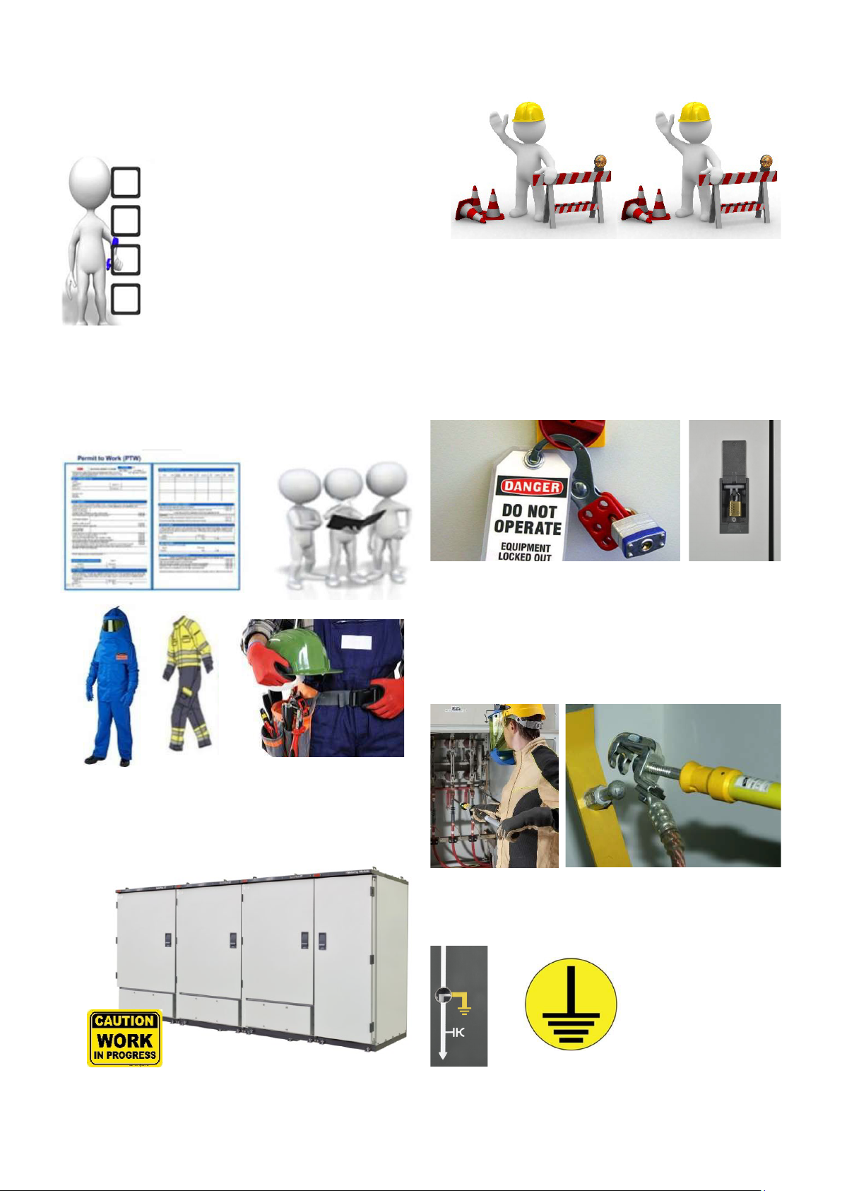
STEP 6 - Protect against adjacent live
parts and take special precautions when
close to bare conductors
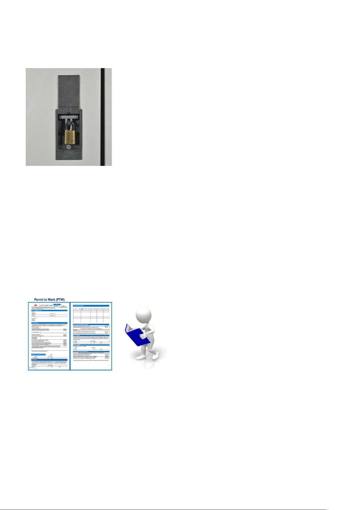
Determine minimum approach distances, apply screening,
and when applicable, padlock both cable and buss bar
shutters, utilize proper insulated gloves and tools for
inadvertent contact potential.
STEP 7 - Complete the permit to work and
“Walk the Permit”
• Check isolation points.
• Ensure all circuits are isolated and secured.
Ensure all parties are integrated with the
Lockout/Tagout.
• Check the earths are properly applied.
• Answer specific questions from the work group.
• Ensure work can proceed without danger.
• Sign the PTW.
1.5 Required Certifications
Training levels
For installations and repairs it is required that the person to
execute the work shall have attended the necessary
training level, see bullets below. Person(s) that have
attended and are certified, are registered in the PCS2
(People Certification System) tool.
Level 1 (L1)
• Basic (Site Operators) for external customers.
• Introductory training for equipment operators.
Level 2 (L2)
• Basic (Equipment Maintainers and Site Operators) for
external customers.
• Advanced training for equipment maintainers and site
operators.
Level 3 (L3)
• Expert for ABB ELDS technicians, engineers, and
approved channel partners
• Certification to perform installation and commissioning,
maintenance and repairs, extension, upgrade and
retrofit, end of life services and replacements at site.
1.6 Disclaimer
When carrying out the installation work, you and your
company agree(s) that the installation is performed solely
at your own risk and that ABB shall not be liable for any
damage or loss of any kind, arising by law or otherwise,
including but not limited to loss of production, business
interruption, loss of profit, loss of revenue, loss of
agreements, loss of goodwill, costs resulting from
non-operation, increased expense of operation or
maintenance, property damage, loss of lives, personal injury,
any and all direct or indirect loss, consequential loss
or damage, resulting from the installation work and/or the
guidance provided by the installation instruction.
Discretion must be exercised when using the installation
instructions.
You and your company agree(s) to indemnify and hold ABB
harmless from and against any and all liabilities,
damages, losses, claims and actions from third parties in
respect of damage to, loss or destruction of property or
to personal injury and death or other claims arising from or
relating to the installation and/or the guidance
provided by the installation instructions.
If any doubt of how to perform the installation, please
search for the relevant training course from ABB.

9INSTALLATION AND OPERATING INSTRUCTIONS
—
2. General description
SafeRing XT/SafePlus XT is a SF6insulated Ring Main Unit
for applications in medium voltage distribution networks.
SafeRing XT/SafePlus XT offers a sealed stainless steel tank
which contains all the live components and switching
functions. The transformer is protected by a vacuum circuit-
breaker.
The units are delivered from the factory ready for
installation.
SafeRing XT/SafePlus XT can be supplied as a 1, 2, 3, 4 or
5 -way unit in standard configurations with additional
equipment according to customer specifications.
Available configurations: Ex- +CC+, +CCC, +CCV, CCCC,
CCCV, +CCVVV+.
SafeRing XT/SafePlus XT has a unique flexibility due to its
extendibility and the possible combination of fully modular
and semi-modular configurations, with a maximum of 5
modules in one SF6tank. The units are delivered from the
factory ready for installation. Routine tests are carried out
on all units/ modules before dispatch.
No special tools are required for installing the equipment.
Available modules are:
• C - Cable switch
• D - Direct cable connection
• V - Vacuum circuit-breaker
• M -Metering cubicle
SafeRing XT/SafePlus XT with vacuum circuit-breaker in
compliance with IEC62271-100
With this unit the transformer will be protected by a vacuum
circuit-breaker combined with relays and current
transformers. The standard relays are based on digital
technology and do not require an external power supply.
Further information can be found in the product catalogue
for SafeRing XT/SafePlus XT.
—
Figure 2.1
SafeRing XT/SafePlus XT 3-way unit +CCV+

10 SAFERING XT/SAFEPLUS XT
2.1 Outer assembly
—
Figure 2.2
Front door open condition
—
Figure 2.3
Front door Closed condition
1. Lifting angle/Lugs
2. Low Voltage compartment
3. Feeder description plate
4. Side Extension covers
5. Manometer
6. On/Off push buttons for Switch Disconnector
7. Voltage presence indicator
8. Switch Disconnector On/Off/Earth Indication
9. Switch Disconnector Operation handle access
10. Switch Disconnector Operation selector knob
11. Fault passage indicator
12. VCB Push button Open/Close
13. Spring Charging Indicator
14. VCB Open/Close Indicator
15. Voltage presence indicator
16. Disconnector On/Off/Earth Indication
17. Disconnector operation handle access
18. Protection relay
19. Disconnector operation selector knob
20. VCB/V Module Mimic
21. Switch Disconnector/C Module mimic
22. Cable compartment door
23. Bottom cover
24. Foundation bracket
25. ABB LOGO
26. Product Designation
27. Main door
28. Main door handle with padlock

11INSTALLATION AND OPERATING INSTRUCTIONS
2.2 Outer assembly Standard Metering Module.
1. Lightning arrester jumpers
2. Lightening arrester
3. Insulating boots
4. R, Y, B jumpers assembly
5. Extension bushing assembly
6. Lifting angle/lugs
7. Auxiliary PT
8. 12 kV PT
9. Low voltage and battery compartment
10. FRTU compartment
—
Figure 2.4
Metering Module outer assembly

12 SAFERING XT/SAFEPLUS XT
—
3. Transport and handling
The units are delivered from the factory ready for
installation.
3.1 Packing
The SafeRing XT/SafePlus XT is normally delivered packed
from the factory. For longer transportation distances,
protective measures such as wooden corners, plastic film
etc., are used. This should be removed, when the RMU is at
site and before installation.
3.1.2 Transport
During transport of packed RMU is to be firmly fixed to the
truck with help of Belts to avoid any damage in transit.
Once Unpacked, SafeRing XT/SafePlus XT is fitted with
lifting lugs but can also be moved on a pallet with a forklift
truck.
Refer the following lifting options available using overhead
cranes or Forklifts for RMU movement.
3.1.3 By receiving inspection
Upon receiving the SafeRing XT/SafePlus XT check that
the delivered equipment has not been damaged during
transport. If any such damage has occurred, a claim must be
submitted to the carrier immediately.
After unpacking, the following must be checked:
1. Operating handle Aone piece is included, normally
fixed on inside of main door.
2. Check that the pointer on the pressure indicator B, is in
the green area.
3. Carry out a function test on the mechanical parts.
4. Visual check of the switchgear. Any faults or omissions
must be reported immediately to the supplier.
5. Loose materials sent along with RMU must be stored
indoor to avoid corrosion/damage to these items.
A
—
Figure 3.1
RMU lifting front view
—
Figure 3.2
RMU lifting Isometric view
—
Figure 3.3
RMU+Metering coupled switchgear lifting
—
Figure 3.4
RMU lifting using Forklift
Caution
The units with heavy top, so please handle with care.
Proper belting must be used while transporting on
forklifts to avoid toppling of the unit. No roller/any other
method should be used for transportation of the
switchgear.
NOTE
Use only approved slings when lifting. Maximum angle
on lifting lugs is set to 90°. Compulsorily use all 4 top
lifting lugs.
—
Figure 3.5
Operating handle

13INSTALLATION AND OPERATING INSTRUCTIONS
B
Above image for representation purpose only, Once it is
installed in RMU, It will indicate the actual pressure inside
the SF6Chamber.
3.2 Storage
SafeRing XT/SafePlus XT must be stored under cover in a dry
and well-ventilated area until it is installed and put into
operation.
3.2.1 Intent
The intent of this procedure is to provide minimum
requirement to ensure suitable and adequate storage
protection are achieved consistently with the environmental
and storage conditions and durations. This is to avoid
damages to the unit due to environmental/atmospheric
impacts.
This procedure provides general standard rules and
minimum requirements (unless otherwise provided for in
the Purchase Order) to be complied with Clients for storage
purposes. This procedure is also referring to packing
procedure.
3.2.2. Codes and standards
International Organization for Standardization (ISO):
ISO9001:2015, Quality Management System Requirements
ISO14000:2015 Environment Management System
Requirements ABB’s Packing Procedure for RMU (SOP)
3.2.3. Storage condition
It is strongly recommended that the unit is strictly stored in
packed condition only (as supplied from ABB (factory). It is
also recommended to store the unit under covered area in a
dry and well - ventilated area until it is installed and put into
operation. Although product is outdoor, it is recommended
to avoid storage of the packed unit under open to sky area
for longer period of time (not more than 3-4 months). The
ground surface level where the unit is stored should be fairly
flat and free from all type of debris. The wooden pallet base
shall be properly rested on the ground.
• Although product is outdoor, it is recommended to avoid
the storage of the packed unit in open to sky, exposed to
direct sun light, atmospheric moisture, gases, fumes,
dust etc. Also recommended to avoid the storage
directly under the rain for the period not more than
two months.
• The Site storage condition shall be dry, clean, flat and
free from all types of debris. It is recommended that, the
unit. The unit is to be protected against dusts, gases,
fumes, rain water, moisture etc.
• The unit must be kept in vertical conditions and must not
be placed in upside down condition or laid down on
sides. The stacking of the one unit above the other unit
or any other equipment stacking over the switchgear
unit is strictly not allowed.
• It is advised that the hazardous and inflammable
materials are not stored nearby where the Ring Main
Units are stored. Also it is recommended to have
adequate firefighting equipment and proper signage’s in
the storage area where the units are stored at site or
warehouse etc.

14 SAFERING XT/SAFEPLUS XT
—
4. Technical data
4.1 Electrical data SafeRing XT/SafePlus XT
Technical Data C-Module V-Module
SafeRing XT/SafePlus XT Switch-
Disconnector
Earthing Switch Vacuum
circuit-breaker
Disconnector-
earthing switch
Rated voltage kV 12 12 12 12
Power frequency
withstand voltage
kVrms 38 38 38 38
Across Disconnector/
Switch-Disconnector
kVrms 45 45 - 45
Lightening Impulse
withstand voltage
kVp 95 95 95 95
Across Disconnector/
Switch-Disconnector
kVp 110 110 - 110
Rated normal current A630 - 630 -
Rated frequency Hz 50 50 50 50
Breaking capacities:
- Active load breaking
current
A630 - - -
- Closed loop breaking
current
A630 - - -
- Cable charging
breaking current
A63 - 31.5 -
- Line charging breaking
current
A 1 - 10 -
- Earth fault breaking
current
A190 - - -
- Cable and line charging
breaking current under
earth fault conditions
A110 - - -
- Short circuit breaking
current
kA - - 21 -
Rated short circuit
making capacity
kAp 52.5 52.5 52.5 52.5
Short time current 3 sec kA 21 21 21 21
Rated filling pressure
(Absolute) at 20°C
Mpa 0.13
Internal arc classification
IAC AFLR
kA/s 10/0.1
Internal arc classification
IAC AFLR
kA/s 21/1

15INSTALLATION AND OPERATING INSTRUCTIONS
—
5. Installation
NOTE!
The unit must be fixed using the bolts
shown in the position in red. Use M10 or
M12 screws.
NOTE!
The tools required for installation and maintenance
of the switchgear are specified in the tool list in
chapter 20.6.
Unit A B C D E
1-way 340 190 290 170 85
2-way 665 515 615 325 170
3-way 990 840 940 650 170
4-way 1315 1165 1265 975 170
5-way 1640 1490 1590 1300 170
5.1 Standard 3-Way Ring Main Unit
—
Figure 5.1
Foundation details Standard 3-Way RMU

16 SAFERING XT/SAFEPLUS XT
(Refer table from Chapter 5.1) (Refer table from Chapter 5.1)
Ring Main Unit 1
(Refer Chapter 2.1)
Ring Main Unit 2
(Refer Chapter 2.1)
5.2 3 way Ring Main Unit + 3 way Ring Main Unit Coupling
5.3 Standard 3-Way Ring Main Unit + Metering Module
Ring Main Unit 1
(Refer Chapter 5.1)
NOTE!
The unit must be fixed using the bolts shown
in the position in red. Use M10 or M12 screws.
NOTE!
The tools required for installation and maintenance
of the switchgear are specified in the tool list in
chapter 20.6.
Ring Main Unit 1 Ring Main Unit 2
—
Figure 5.2
Foundation View coupled RMU
—
Figure 5.3
Foundation View Standard 3-Way RMU+ Metering module

17INSTALLATION AND OPERATING INSTRUCTIONS
Flatness of concrete plinth area should be within ±2 mm. This area only considers switchgear
foundation. Concrete plinth height of minimum 700 mm is recommended.
M10 Hot Dip Galvanized
Hex Nut
Foundation Bracket of
RMU
M10 Hot Dip Galvanized
Cup Washer
Hot Dip Galvanized
M10x100 Anchor Bolt
*Maximum limit is 60mm
*40mm
Hot Dip Galvanized
M10x100 Anchor Bolt
Foundation Bracket of
RMU
*40mm
Wherever it is not possible to have proper leveling, use channel, ISMC-75 as per IS-2062/1999.
Alternatively, unit can be directly bolted to the concrete foundation with suitable M10 Fischer bolts
—
Figure 5.4
Foundation details

18 SAFERING XT/SAFEPLUS XT
Cables for
representation
purpose only
—
6. Dimensions
6.1 Weight table
SafeRing XT/SafePlus XT the weights are
Module RMU weight In kg
1 Way (V….etc) 175
2 Way (DV, CV…etc) 350
3 way (CCV, CCC…etc) 525
4 Way (CCVV….etc) 700
5 Way (CCVVV…etc) 825
Metering Module 325
NOTE!
ABB wishes to highlight that values of dimensions and
weights provided herein are preliminary and may change
after final design preparation, based on final scope of
supply and installation details of the switchgear. As a
consequence, provided values of dimensions and weights
are NOT to be considered as final but only for standard
reference purposes.
ACCORDINGLY, YOU EXPRESSLY ACKNOWLEDGE AND
AGREE THAT VALUES OF DIMENSIONS AND WEIGHTS
PROVIDED HEREIN ARE NEITHER FINAL NOR BINDING
AND THAT THE RESULT OF THEIR USE IS NEITHER
FEASIBLE NOR ACCURATE NOR ERROR FREE.
6.2 Dimension
—
Figure 6.1
Standard 3-Way RMU
—
Figure 6.2
Standard metering module

19INSTALLATION AND OPERATING INSTRUCTIONS
—
7. Internal arc classification (IAC)
During development of all ABB products, focus is on
personnel safety. The SafeRing XT/SafePlus XT portfolio was
designed and tested to withstand a variety of internal arc
scenarios at the same current level as the maximum short
circuit current.
The tests show that the metal enclosure of
SafeRing XT/SafePlus XT is able to protect personnel
standing close to the switchgear during internal arc fault.
Causes and effects of internal arcs
Although an internal arc fault is highly unlikely it can
theoretically be caused by various factors, such as:
• Insulation defects due to quality deterioration of the
components. The reasons can be adverse environmental
conditions and a highly polluted atmosphere.
• Inadequate training of the personnel in chargeof the
installation leading to incorrect installation of the cables.
• Broken or modified safety interlocks.
• Overheating of the contact area, e.g. when the
connections are not sufficiently tightened.
• Short circuits caused by small animals that have entered
into the cable compartment (i.e. through cable entrance).
The energy produced by the internal arc causes the
follow- ing phenomena:
• Increase of the internal pressure.
• Increase of the temperature.
• Visual and acoustic effects.
• Mechanical stresses on the switchgear structure.
• Melting, decomposing and evaporation of materials.
Tested according to IEC standard 62271-200
The capability of SafeRing XT/SafePlus XT switchgear to
withstand internal arc is proven by type tests performed
according to internal arc classification (IAC) as described in
the standard IEC 62271-200 as follows:
Accessibility: A and B (switchgear) A = Accessible to
authorized personnel only 300 mm safety distance on
accessible sides of the switchgear (also distance to sensors
during testing) B = public access 100 mm safety distance on
accessible sides of the switchgear (also distance to sensors
during testing)
Accessible sides of switchgear = Area that personnel can
enter freely. For accessibility A this means a 300 mm safety
distance + 500 mm or more in safe moving area.
Non-accessible side of switchgear = Area that is physically
blocked or clearly marked as not safe for personnel.
All test specimens passed the following test criteria
according to the standards:
1. Correctly secured doors and covers do not open
2. No fragmentation of the enclosure occurs within the
time specified for the test. Projection of small parts up
to an individual mass of 60 g are accepted
3. Arcing does not cause holes in the enclosure of the
switchgear up to a height of 2 m
4. Indicators do not ignite due to the effect of hot gases
5. The enclosure remains connected to its earthing point
—
Graph 7.1
Arc duration vs damage caused
R
L
F
L
F-Front = Access from the front
L-Lateral = Access from sides
R-Rear = Access from the rear
—
Figure 7.1
Access details for standard RMU

20 SAFERING XT/SAFEPLUS XT
SafeRing XT/SafePlus XT is available for a wide range of
installations and applications in order to secure the highest
safety for operators.
Switchgears are designed and type-tested for internal arc
classification according to the following configurations:
7.1 IAC AFLR
Downwards ventilation with ventilation down to the cable
trench/floor beneath.
With this setup, hot gases and pressure are evacuated
downwards in the cavity in the floor beneath the switchgear.
Hot gases are led to the cable trench by means of a bottom
flap installed on the bottom side of the switchgear, forcing
the hot gases down during an arc fault. The switchgear
must be arranged as instructed according to the basic
parameters below.
Basic parameters of set-up:
• IAC AFLR up to 10 kA / 0.1s & 21kA /1s
• Minimum height of ceiling: 3000 mm
• Recommended distance to Rear/Lateral wall:
- 800 mm with accessible Rear/Lateral side
- 100 mm recommended for non-accessible Rear/
Lateral side.
- 700mm Minimum height of the cable trench
- 700mm Minimum depth of the cable trench
*Distance from ground level
7.2 Non-arc proof version
The non-arc proof version of the metering module is not
verified for any of the IAC-classes. In the highly unlikely
event of an internal arc fault in the switchgear, hot gases
and pressure could evacuate randomly in any direction at
any place of enclosure.
• Switchgear needs to be installed and fixed to the floor
(see Chapter 5).
CAUTION!
Do not to block red dotted highlighted area as it is the
passage for internal arc fumes/gases.
—
Figure 7.2
Arc/hot gases flow- tank
—
Figure 7.3
Arc/hot gases flow- cable compartment
This manual suits for next models
1
Table of contents
Other ABB Industrial Equipment manuals
Popular Industrial Equipment manuals by other brands

Afag
Afag aflex 150 Original operating manual

SMC Networks
SMC Networks ZL112A Series operating manual

Balluff
Balluff BNI IOL-104-011-K006 user guide

Flowserve
Flowserve Limitorque HBC Series User instructions

Redline Engineering
Redline Engineering 500HWC manual

Afag
Afag CR 20-ZA Assembly & operating instructions