ABB HD5-B-101 User manual

Original instructions
HD5-B
Three position enabling device with safe AS-i slave

2
Read and understand this document
Please read and understand this document before using the products. Please consult your ABB
Electrification Sweden AB representative if you have any questions or comments.
Suitability for use
ABB Electrification Sweden AB shall not be responsible for conformity with any standards, codes, or
regulations that apply to the
combination of products in the customer’s application or use of the product. At the customer’s request,
ABB Electrification Sweden AB will provide applicable third-party certification documents identifying ratings
and limitations of use that apply to the products. This information by itself is not enough for a complete
determination of the suitability of the products in combination with the end product, machine, system, or
other application or use.
The following are some examples of applications for which attention must be given. This is not intended to
be an exhaustive list of all possible uses of the products, nor is it intended to imply that the uses listed may
be suitable for the products:
• Outdoor use uses involving potential chemical contamination or electrical interference, or conditions or
uses not described in this document.
• Nuclear energy control systems, combustion systems, railroad systems, aviation systems, medical
equipment, amusement machines, vehicles, and installations subject to separate industry or government
regulations.
• Systems, machines, and equipment that could present a risk to life or property.
Please know and observe all prohibitions of use applicable to the products.
NEVER USE THE PRODUCTS FOR AN APPLICATION INVOLVING SERIOUS RISK TO LIFE OR PROPERTY
WITHOUT ENSURING THAT THE SYSTEM AS A WHOLE HAS BEEN DESIGNED TO ADDRESS THE RISKS, AND
THAT THE ABB Electrification Sweden AB IS PROPERLY RATED AND INSTALLED FOR THE INTENDED USE
WITHIN THE OVERALL EQUIPMENT OR SYSTEM.

3
Table of contents
1. INTRODUCTION .............................................................................................................................................................. 4
PURPOSE ....................................................................................................................................................................................... 4
TARGET GROUP ............................................................................................................................................................................... 4
PREREQUISITES ............................................................................................................................................................................... 4
SPECIAL INSTRUCTIONS ..................................................................................................................................................................... 4
2. SAFETY ........................................................................................................................................................................... 5
INTENDED USE ................................................................................................................................................................................ 5
CORRECT USE ................................................................................................................................................................................. 5
FORESEEABLE MISUSE ................................................................................................................................................................. 5
APPROVED PERSON .......................................................................................................................................................................... 6
SAFETY PRECAUTIONS ....................................................................................................................................................................... 6
GENERAL SAFETY INFORMATION ......................................................................................................................................................... 6
DISPOSAL ....................................................................................................................................................................................... 7
3. PRODUCT DESCRIPTION ................................................................................................................................................. 8
HD5-B-XXX ................................................................................................................................................................................... 8
PRODUCT RANGE ............................................................................................................................................................................. 8
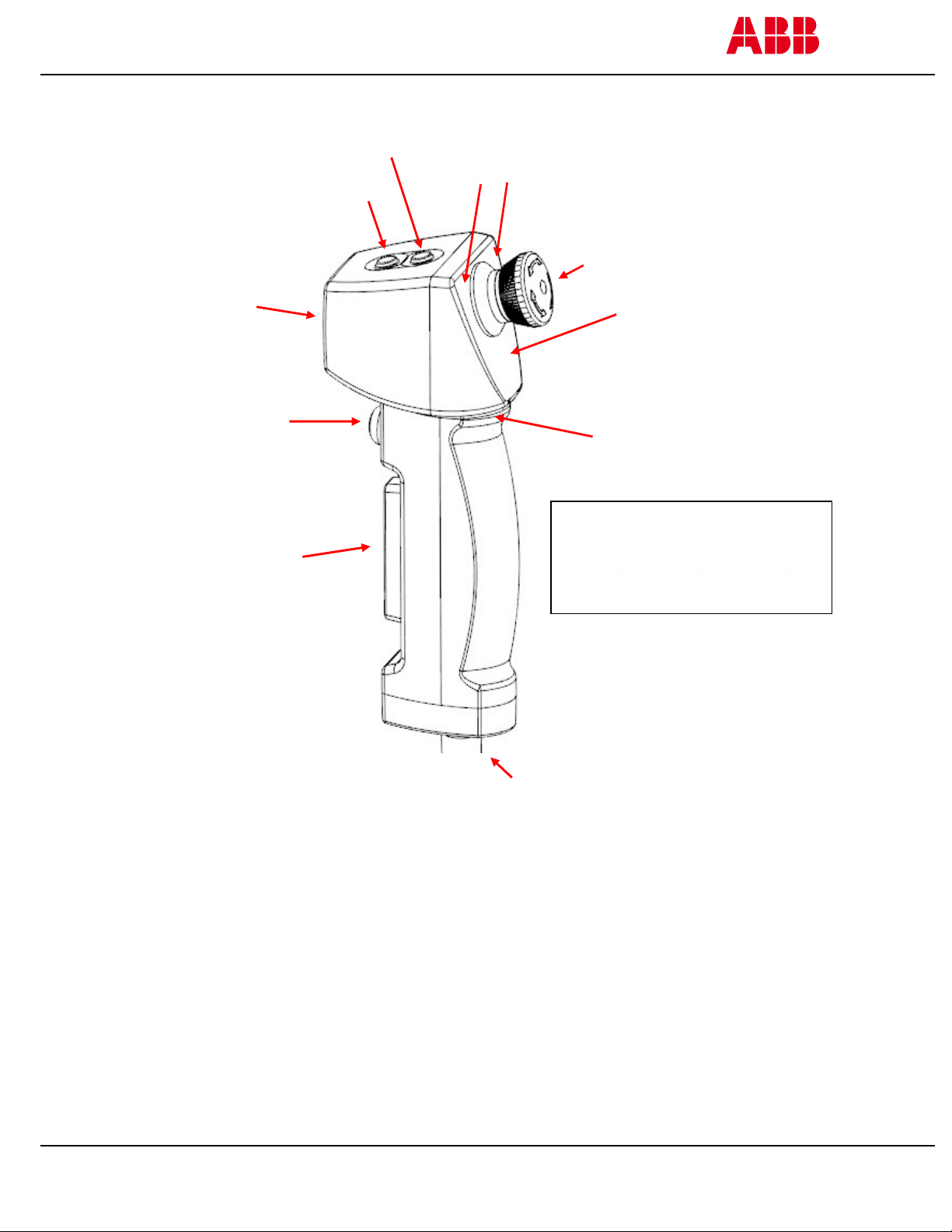
4. FUNCTION DESCRIPTIONS ............................................................................................................................................ 10
THREE-POSITION BUTTON ............................................................................................................................................................... 10
EMERGENCY STOP BUTTON .............................................................................................................................................................. 11
EMERGENCY STOP LED ................................................................................................................................................................... 12
FRONT BUTTON ............................................................................................................................................................................. 13
TOP BUTTONS ............................................................................................................................................................................... 13
SIGNAL LED ................................................................................................................................................................................. 14
HOME POSITION SENSOR ................................................................................................................................................................. 14
ASSIST LIGHT ................................................................................................................................................................................ 14
STATUS LED FOR AS-I BUS ............................................................................................................................................................. 15
5. CONNECTIONS HD5-B-XXX ........................................................................................................................................... 16
6. INSTALLATION .............................................................................................................................................................. 17
7. MAINTENANCE ............................................................................................................................................................. 19
8. MODEL OVERVIEW, ACCESSORIES ................................................................................................................................ 20
HD5-B-XXX .............................................................................................................................................................................. 20
HD5 ACCESSORIES .................................................................................................................................................................... 21
9. TECHNICAL DATA .......................................................................................................................................................... 22
AS-I DATA .................................................................................................................................................................................... 25
ABB VERSIONS HD5-B-XXX ............................................................................................................................................................ 25
10. DIMENSIONS ............................................................................................................................................................ 26
THREE POSITION DEVICE HD5-S-XXX ................................................................................................................................................. 26
HOLDER HD5-M-00X ................................................................................................................................................................... 26
11. EC DECLARATION OF CONFORMITY .......................................................................................................................... 27

4
1.
INTRODUCTION
Purpose
The purpose of this operating manual is to describe the HD5-B-xxx three position enabling device
and to provide the information necessary for planning, assembly, maintenance, and operation.
Target group
This document is aimed at planners, as well as specialist staff working in assembly and maintenance.
In addition, this operating manual is aimed at users who have received training and authorization, from the
operator of the facility, in relation to these devices, how to handle them, and the hazards they pose.
Prerequisites
It is assumed that the reader of this document has the following knowledge:
Basic knowledge of ABB Electrification Sweden AB products
Knowledge of the AS-i Bus system
Knowledge of safety products
Knowledge of safety control devices with functions relevant to safety
Knowledge of related facilities
Special instructions
Please pay attention to the following special instructions in this document:
Attention!
Danger of personal injury!
Failure to follow instructions or work sequences properly may result in personal
injury.
Caution
Risk of damage to the equipment!
Failure to follow instructions or work sequences properly may result in damage to
the equipment.
Note Notes are used to provide important or explanatory information.

5
2. SAFETY
Intended use
HD5-B-xxx is a three-position enabling device with integrated AS-i technology, according to the AS-i
specification V 3.0, it is operated in the standard addressing mode. (see chapter "AS-i data")
The device is intended for connection to an AS-i safety bus and connected to a suitable safety controller.
Additionally, the machinery or the equipment causing the potential danger needs to be put in jog position
or otherwise restricted in movement, speed, temperature, etc.
The operator pushes the large black button to a middle position in order to allow a movement. In case of
danger, the operator will either release the button or squeeze it to its bottom position and the machine will
stop. Some models offer additional top and front buttons to control a non-safe signal, e.g. move forward
and/or backward.
Correct use
The protective function of the safety device is only safe if the safety controller is correctly connected and
configured.
Obey the following conditions to prevent misuse and cause danger:
Make sure that these instructions are included together with the documentation of the system to which
the protective device is attached to.
Make sure that these instructions always are available for the operators.
The three-position device must only be used after it has been selected refereed to related instructions,
relevant standards, rules and regulations for labor protection and safety at work, and when installation,
connection, check and start-up are done by an approved person.
The three-position device must be connected and started according to its specifications, for example
the technical data.
The three-position device must be connected so that its safety related capacity meets or exceed the
performance level (PL) or safety integrity level (SIL) that has been estimated in the risk analysis.
The three-position device must not be modified. If the design or the functions are changed the
protective function can be damaged and the warranty of the three-position device is not applicable.
Repair and exchange of parts of the three-position device is not permitted.
The three-position device must be tested regularly by an approved person.
The three-position device must be exchanged within a mission time 20 years, due to requirement in EN
ISO 13849-1. Depending on the use (calculation of T10D, se 6. Performance Level (PL) Calculation), the
three-position device might have to be exchanged within a shorter time than 20 years.
Foreseeable misuse
Other use than defined as correct use and foreseeable misuse, or which is beyond that use, is
considered as incorrect use.
The three-position device is not by itself a complete protective device.
The three-position device is not intended for use in explosive or easily flammable adjacent air.

6
Approved person
An approved person must have ...
A suitable technical education.
Knowledge about rules and regulations for occupational safety, safety at work, safety technology and
how to estimate the safety of the machine.
Received instructions from the person that is responsible for the installation and operation of the three-
position device and the device/machine which it is connected to.
See Chapter Intended use and Chapter Correct use for further information
Safety precautions
The following safety precautions must be followed during installation, operation, maintenance and
troubleshooting.
General safety information
Attention!
Carefully read through this entire manual before using the product.
Always respect the documented minimum or maximum values of the product.
For installation and prescribed use of the product, the special notes in these instructions must be
carefully observed and the technical standards relevant to this product must be considered.
This product must be installed by a trained electrician following applicable safety regulations, standards
and the machine directive.
Failure to comply with these instructions, operation that is not in accordance with the use prescribed in
these instructions, improper installation or handling of the device can affect the safety of people and
the plant.
In case of failure to comply with these instructions or the applicable standards, especially when
tampering with and/or modifying the product, liability is excluded.
The safety functions of the product must be tested before the system is put in operation.
The safety functions of the product must be tested after installation or replacement of components or
cables.
The safety functions and the mechanics of the product must be tested regularly to confirm that all the
safety functions are working properly.
In case of breakdown or damage to the product, contact ABB Electrification Sweden AB. Do not try to
repair the product. It might accidentally cause permanent damage, impairing the safety of the product
and in turn lead to serious personnel injuries.

7
Caution!
Please note, if you in non-compliance with the specifications and restrictions of these operating
instructions (e.g. duty cycle, temperature, etc.) can lead to the functionality of the enabling device failing
and unintended machine stop.
After a shutdown in according to this, the function of the 3-position enabling device will be restored, if the
values below the limits. But a probable damage to the electronics and a reduction of service life can´t be
ruled out.
Disposal
The three-position device shall be disposed in accordance with WEEE directive, 2012/19/EU.

8
3. PRODUCT DESCRIPTION
HD5-B-xxx
HD5 is a three-position device designed for use in hazardous areas where alternative protective devices are
not possible or practical.
The “HD5-B-xxx” enabling device is designed to be connected to a Safety controller via AS-i Safety-Bus.
Additionally, the machinery or the equipment causing the potential danger needs to be put in jog position
or otherwise restricted in movement, speed, temperature, etc.
The operator pushes the larger black button to a middle position in order to allow a movement. In case of
danger, the operator will either release the button or squeeze it to its bottom position and the machine will
stop. Some models offer additional top and front buttons to control a non-safe signal, e.g. move forward
and/or backward.
The signals from the three-position enabling switches and the emergency stop button (if the device is
equipped with this) are detected by the integrated electronics and transmitted to the AS-i safety monitor
via the safe slave.
Signals used to provide haptic or visual feedback are transmitted from additional integrated command
buttons and sensors to the AS-i logic and from the AS-i logic to the enabling device via a third, unsafe slave.
The enabling device is connected to the AS-i Bus in the usual way using a fixed spiral-cable or via a M12
connector built into the device.
Product range
The HD5-B product range includes the following models.
Function
HD5-B-101 HD5-B-102
1 Three-position button Yes Yes
2 Emergency stop button Yes No
3 Emergency stop button status LED Yes No
4 Front button [S4] Yes Yes
5 Top button [S5] Yes Yes
6 Top button [S6] Yes Yes
7 LEDs red and green Yes Yes
8 Assist Light Yes Yes
9 Connector M12- 5 pin M12- 5 pin
10 Home position sensor Yes Yes
11 Motion sensor No No
12 -------------------- ----------- -----------
13 AS-I Status LED Yes Yes
* position-no., regarding to the picture on next side

9
9
.
Connector
5
.
TOP button [5]
6
.
TOP button [6]
7. LEDs
“
r
ed
“
and “green
“
2
.
Emergency stop
button
3.
E
mergency stop button
status LED
4.
Front button [S4]
1.
Three
-
position button
8
.
Assist Light
Integrated in housing:
10. Home position sensor
11. Motion sensor
12. ----------
1
3
.
AS
-
i Status LED

10
4.
FUNCTION DESCRIPTIONS
Three-position button
The three-position button provides signals, which:
When activated, allow the machine or equipment to be activated using a separate
start control signal.
When deactivated, initiate a stop function which prevents the machine or
equipment from starting.
Two three-position switches are used and controlled simultaneously to create a two-
channel architecture.
An important feature of the three-position button is that when it is released from
position 3, the ON position is never reached, i.e. the contacts remain open. The three-position button always
go back to position 1 when released.
The three-positions functionality:
Position 1 (O): OFF mode the button is not pressed, contacts are open.
Position 2 ( I ): ON mode the button is pressed in the middle position, contacts are closed
Position 3 (O): OFF mode the button is fully pressed to bottom position, contacts are open.
Note on operation
To ensure a correct and safe operation, the three-position
button must be pressed to the middle position with two or
three fingers.
1 2 3

11
Emergency stop button
The built-in emergency stop button has two force guided normally closed contacts.
The emergency stop button shall initiate an emergency stop function, thereby removing
energy to the hazardous functions in the event of emergency.
The holders developed for this three-position device allow for the emergency stop
button to be pressed when the three-position device is placed in the holder.
LEDs integrated in the housing indicate the status of the emergency stop button.
Note on safe actuation
To allow for the emergency stop button to operate safely, we recommend using the holders designed for
this three-position device. See the accessories section.
Attention!
Caution should be exercised in relation to three-position devices that are connected, as standard, using a
connector. Be aware of the following items:
The correct function of the emergency stop must be check monthly!
The emergency stop function must always be functional and should have priority over all other functions
and operations in all operating modes of the machine without affecting any system intended to release
trapped persons.
No start command (whether intentional, unintentional or unexpected) should be able to affect working
processes that were stopped by initiating the emergency stop function until the emergency stop
function has been reset manually.
If it is possible to remove emergency stop buttons (e.g. portable programming devices) or shut down
sections of a machine, it must be ensured that operational and non-operational emergency stop
buttons are not mixed.

12
Emergency stop LED
A row of LEDs is integrated in the housing, below the emergency stop button.
Attention!
The controls for the feedback LED are independent from the emergency stop button function.
The programmer is solely responsible for their signaling function.
ABB Electrification Sweden AB does not accept any liability for damages of any kind caused by signaling
that is not logical, and the resulting misjudgements and errors by users.
Red LED row
(controlled via AS-i Bus)
Green LED row
(is is possible to activate and controlled according the following table)
LED row red
controlled via AS-I Bus
function LED green
controlled via AS-I Bus LED row green
Off not activated Off
On not activated Off
Off activated On
On activated Off

13
Front button
The front button is located above the three-position button.
The button is user-defined and can be controlled via wiring.
Attention!
This signal is not failsafe and must not be used for a safety function.
Note on activation of front button
The button must be pressed down vertically. If the angle exceeds 15° when actuating the switch, the switch
contact may be damaged, reducing it lifetime (number of switching cycles).
Top buttons
The two top buttons are located at the top part of the HD5.
The buttons are user-defined and can be controlled via wiring.
Button [S5] is marked -
Button [S6] is marked +
Attention!
This signal is not failsafe and must not be used for a safety function.
[S5]
[S6]

14
Signal LED
A green and a red LED are integrated in the housing, above the emergency stop
button. The LEDs are user-defined and can be controlled in via AS-I Bus.
Home position sensor
This function provides information as to whether the three-position device is in its holder.
The home position sensor delivers a signal, transmitted via AS-I Bus when HD5 is in place in the
active holder (HD5-M-001). The holder is available as an accessory.
Attention!
This signal is not failsafe and must not be used for a safety function.
Assist Light
The assist Light is in the front of the HD5 and can be used for short
periods when the ambient light is insufficient.
Controll of the function via AS-I Bus.
Note on duty cycle
For ambient temperatures ≤ 35°C, the flashlight should never be used longer than 15 min at a time and
max 60% on-time
For ambient temperatures over 35°C, the flashlight should never be user more than 10 min at a time and
max 40% on-time
On-time percentage = [on time/ (on time + off time)] x 100
Caution
The increased heat can damage the device. Make sure to comply to the above requirements.
If the device had stopped working because of temperature rise, it will work again once the values have
dropped below the limits. However, there may still be damage to the electronics and a reduction in product
lifetime.
Attention! Hazards arising from glare
Avoid looking directly into the lens of the assist light. Looking directly into the lens, and the glare effect
which may result from it, can sometimes impair vision, cause irritation, and result in accidents.

15
Status LED for AS-i Bus
One green and one red LED will inform you, about the status of the slave on the
AS-i Bus.
The LEDs are positioned in a way that means they are not directly visible when the
enabling device is placed in the holder intended for this purpose.
The reason of the positioning is to avoid confusing the user with too many visual
signals
AS-i (green) Fault (red) Description
Off Off No power supply to AS-i
ON Off Normal operation
Off ON AS-i communication disrupted
Flashing ON No data exchange because address = 0
alternating flashing alternating flashing Peripheral error
Off flashing Recognizes double addresses (ABB version only)

16
HD5
-
B
-
101
HD5
-
B
-
102
5.
CONNECTIONS HD5-B-xxx

17
6. INSTALLATION
This chapter contains information about the installation procedures for the three-position device.
Connect the cable to the control device and connect the HD5 to the cable.
Mount the holder
Make sure that the three-position device is completely in the holder.
Make sure that the connection cable is an original cable from ABB and protected from mechanical
damage to ensure highest safety and reliability.
Make sure that the cable carrying the control signals from the three-position device is physically
separated from cables that carry power.
Attention!
Installation shall be done by an approved person (see Chapter Approved person) with knowledge on AS-i
Bus Systems.
The position should be selected in view of ergonomic and safety relevant aspects.
Other protective measures must be taken in order to protect other people in the same or in adjacent
hazardous areas.
The safety functions of the product must be tested before the system is put in operation.
The safety functions of the product must be tested after installation or replacement of components or
cables.
The safety functions and the mechanics of the product must be tested regularly to confirm that all the
safety functions are working properly.
Attention!
in accordance to the national electrical codes, cables that carry power (mains power
lines, power circuits with a high di/dt, switch-mode converters, power-regulation
control devices) and cables that carry control signals must be physically separated.
The connection cable of this device carries control signals and must be laid in the cable
area for control signals.
Otherwise, a risk of material damage or personal injury cannot be ruled out

18
Note on the connection on AS-I Bus
When using enabling devices with connectors, always use cables without additional shielding for reasons of
interference immunity.
Cables for harmless use can be found in the accessories chapter or on request.
If the enabling device is connected by spiral cable, the maximum line length must be reduced by 12m per
enabling device when an AS-i line is occupied by more than three type HD5-B-xxx enabling devices.
A recommended method for connection is the type shown in the picture on the right
using an M12 connector.
The M12 connector is assigned to pin 1 (AS-i +) and pin 3 (AS-i -) as standard.

19
7. MAINTENANCE
The three-position device itself does not require any maintenance in addition to regular functional testing
and cleaning.
The emergency stop safety function must be checked monthly. All safety functions and mechanisms must
be tested regularly, at least once a year, to confirm that all the safety functions are working as they should.
Depending on the application, machine manufacturers may stipulate requirements for shorter maintenance
intervals. If this is the case, such requirements should be given priority. As a rule, it is recommended to
document all maintenance work.
To ensure that command buttons continue to function in the long term, it is advisable to regularly wash
them with a soft cloth and a standard (soap-based) multi-purpose cleaner.
The connection cable must be inspected regularly and replaced in case of damage. Make sure that the cable
is an original cable from ABB to ensure highest safety and reliability.
Caution
The degree of protection of the three-position device specified in the data sheet must be met during
cleaning.
The operating surfaces are made of soft, elastic and very thin material designed to be hard wearing. Using
abrasive cleaning agents or sharp-edged tools can weaken or penetrate the surface, which results in the
protection class being lost in a relatively short space of time. (Dirt and moisture may penetrate the housing)
The use of cleaning agents containing solvents should be avoided. This is not only to protect the surfaces,
but also to protect the health of employees.
Attention!
If the device is not working or is damaged, the device must immediately be put out of service. Please
contact your regular contact for maintenance work or your nearest ABB customer service or dealer. Do not
attempt to repair the product yourself. Any attempt to interfere with the device will result in a loss of
warranty. A damaged product can affect the function and the safety and how it functions, which may lead
to serious injury.

20
8.
MODEL OVERVIEW, ACCESSORIES
HD5-B-xxx
Type Article number Description
HD5-B-101 2TLA920502R0003 3-pos button, 1 front button, 2 top buttons, Emergency
stop, flashlight, home position sensor
HD5-B-102 2TLA920502R0004 3-pos button, 1 front button, 2 top buttons, flashlight,
home position sensor
HD5-B-101 HD5-B-102
This manual suits for next models
1
Table of contents
Other ABB Industrial Equipment manuals