manuals.online logo
Brands
  1. Home
  2. •
  3. Brands
  4. •
  5. ABB
  6. •
  7. Inverter
  8. •
  9. ABB REACT-BATT-AP1 User manual

ABB REACT-BATT-AP1 User manual

In addition to what is explained below, the safety and installation information provided in the
installation manual must be read and followed. The technical documentation and the interface
and management software for the product are available at the website.
The device must be used in the manner described in the manual. If this is not the case the
safety devices guaranteed by the inverter might be ineffective.
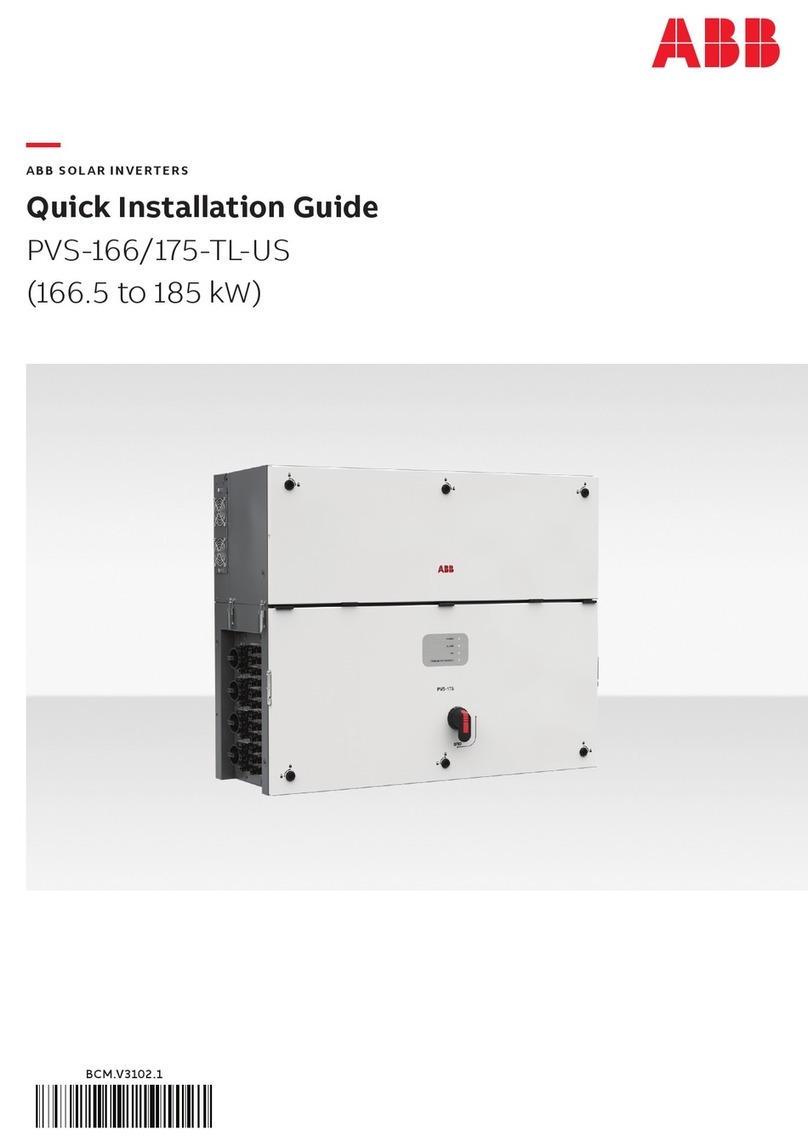
Quick Installation Guide
REACT-BATT-AP1
ABB Solar inverters
1.
Labels and SymbolsEquipment Models and Components
2.
EN
Safety precautions
4.
Lifting and transport
5.3.
List of supplied components
The labels on the equipment have the Agency marking, main technical data and identication of the equipment and manufacturer
HAZARD. The hazard warnings (set out below) are used to indicate risks or unsafe practices that CAN cause serious injury or death.
• DO NOT dismantle or disassemble the parts of the battery pack (REACT-BATT-AP1). The battery pack has safety functions and protection circuits which could
be compromised by improper use.
• DO NOT set light to or heat the battery pack. Possible damage or melting of the insulation with consequent loss of the safety conditions due to the release of
gas or burning of electrolyte material. The battery pack could produce heat, smoke, breakages or ames.
• DO NOT use or leave the battery pack near a naked ame, boiler or heated places (beyond the temperature range indicated in the technical data).
• DO NOT immerse or wet the battery pack with fresh or salt water. The battery pack could produce heat, smoke, breakages or ames.
• DO NOT break into, strike or stamp on the battery pack; this could deform, damage or short-circuit the battery pack. The battery pack could produce heat,
smoke, breakages or ames.
• DO NOT create damaging impacts or drop the battery pack. The battery pack could be damaged.
• DO NOT use the battery pack for other equipment. The battery pack REACT-BATT-AP1 must be used solely with the inverter REACT-UNO-XX
• DO NOT touch the battery pack directly if there is a leak of electrolyte material. Should the electrolyte material come into contact with the eyes, wash the eyes
with plenty of fresh water as soon as possible, without rubbing them. Then consult a doctor. If no treatment is applied, there could be problems for the eyes.
• DO NOT touch the battery pack if it shows any breaks in the plastic cover where any parts under voltage are visible.
• DO NOT use the battery pack should a fault or any anomaly (such as in smell, heat, colour, smoke, shape or noise) be found. The battery pack could produce
heat, smoke, breakages or ames.
WARNING. The warnings (set out below) are used to indicate risks or dangerous actions which COULD cause serious personal harm or
damage to the product or property.
• DO NOT use the battery pack REACT-BATT-AP1 with other battery models if not expressly indicated by ABB.
• DO NOT use a battery pack that is leaking electrolyte material. The electrolyte material which has leaked from the battery could burn or catch re and cause
smoke, breakages or ames.
• DO NOT use the battery pack if it shows anomalies. Should the battery pack have a bad smell, changes in colouring, deformation or other anomalous condi-
tions during use (including charging and storage), do not use it. If an anomalous battery pack is used, it may produce heat, smoke, breakages or ames.
CAUTION. The caution messages (set out below) are used to indicate risks or dangerous actions which could cause serious harm to people
or damage to property.
• DO NOT use or leave the battery pack exposed to direct sunlight (or in a vehicle which is exposed to the sun). The battery pack could produce heat, smoke,
breakages or ames. In addition, its performance might deteriorate and/or it might have a shorter lifespan.
• If the battery pack has signs of rust, a bad smell or any anomaly on rst being used, do not use the equipment.
• If the skin or clothes come into contact with electrolyte material which has leaked from the battery pack, wash them in plenty of fresh water as soon as possi-
ble, otherwise it might cause inammation of the skin.
Final installation of the equipment must not hinder access to any externally located disconnection devices.
Please refer to the warranty terms and conditions to evaluate any possible warranty exclusions due to improper installation.
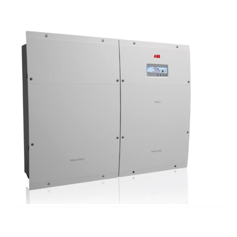
The model of equipment to which this guide refers is REACT-BATT-AP1.
The principal components of the REACT-BATT-AP1 are shown in the gure and described in the following table:
3837
394041
424344453635131411
Main components
11 Front cover
14 Battery unit (REACT-BATT-AP1)
13 Battery pack
35 Ground connection points
36 Cabling bypass male ange
45 Internal battery communication (cable to left unit)
44 Switch for setting the termination resistance of the internal battery communication
43 Internal battery communication (cable from right unit)
42 Rotary switch (RS485 internal line address)
41 Communication connector (cable to left unit)
40 Smoke sensor
39 Communication and control connector (cable from right unit)
37 Power connector (cable to left unit)
38 Power connector (cable from right unit)
Transport and handling
Transport of the equipment, especially by road, must be carried out with by suitable ways and means for protecting the components (in particular, the electronic
components) from violent shocks, humidity, vibration, extreme temperatures, etc.
The REACT-BATT-AP1, as it falls within the category of dangerous goods (UN 3480 lithium-ion battery, class 9, group II), must comply with the rules of the
ADR (European Agreement concerning the International Carriage of Dangerous Goods by Road) as regards packaging, transport and marking.
For more information, consult the website of the Ministry of Infrastructure and Transport on page http://www.mit.gov.it/mit/site.php?o=vc&lm=2&id_cat=207).
Exemptions from the provisions:
• the “Ancillary rule” (1.1.3.1 c ADR)
• the “1,000 Units rule” (1.1.3.6 ADR)
-End of life battery unit transportation
Besides complying with the general application of the ADR, Battery Units which are transported for disposal must comply with the following guidelines:
- Be packed in accordance with packing instruction P909 of 4.1.4.1
- Packages that need to be marked: “LITHIUM BATTERIES FOR DISPOSAL”, in addition to other labels and indications provided for in the ADR.
For further details, please refer to the ADR document: “European Agreement concerning the International Carriage of Dangerous Goods by Road”, special
regulation 377.
Storage of REACT-BATT
The storage of REACT-BATT starts from the moment of delivery by ABB. In order to guarantee the full operation of the system, REACT-BATT must be put into
service within 1 year at most of the date of production.
In order to reduce risks during storage of the REACT-BATT it must be considered that:
• In the case of damage to the REACT-BATT there is a high risk of re.
• Keep the REACT-BATT in a dry place.
• Relative humidity, not condensing: 5% … 95%
• Handle and treat packages carefully.
• Avoid unnecessary movements of the REACT-BATT.
• Ambient temperature allowed during storage: -5°C...+40°C
• Maximum height above sea level (a.s.l.): = 2 000 m
For the rules on storing the battery, refer to the regulations in force in the country concerned
- Handling of damaged batteries
Should damage or visible deformation of the cover be found, or should it be noted that the batteries have overheated during operation, immediately contact the
ABB technical assistance service.
Lifting
Risk of injury due to the weight of the equipment.
Where indicated and/or where there is a provision, eyebolts or handles, which can be used as anchorage points, are
inserted and/or can be inserted.
The ropes and means used for lifting must be suitable for bearing the weight of the equipment.
- Equipment weight
Model Weight (kg/lb) Lifting points
REACT-BATT-AP1 37kg / 81.5lb 4 (2 people)
Unpacking and checking
Bear in mind that the packaging elements (cardboard, cellophane, staples, adhesive tape, straps, etc.) may cause cuts and/or injuries if not handled with care.
They should be removed by suitable means and not left in the hands of individuals who are not responsible (e.g. children).
The packaging components must be disposed of in accordance with the regulations in force in the country of installation.
When you open the package, check that the equipment is undamaged and make sure all the components are present.
If any defect or damage is detected, please stop, contact the carrier and also promptly inform the ABB Service
Disposal of battery unit
ABB is responsible for the battery unit disposal. Contact the local ABB service for further details.
At the end of its life cycle, Battery Unit can be packed and transported by trained personnel in accordance with Chapter 1.3 ADR - See section “Transport of
batteries at end of life”.
In case the original packing of the Battery Unit is no longer available, you may request a new one by contacting the ABB service.
In the manual and/or in some cases on the equipment, the danger or hazard zones are indicated with
signs, labels, symbols or icons.
Always refer to instruction manual General warning - Important safety
information
Positive pole and negative pole of
the input voltage (DC)
Temperature range
Hazardous voltage Hot surfaces
Always use safety clothing and/or
personal safety devices
Point of connection for grounding
protection
The labels attached to the equipment must NOT be removed, damaged, dirtied,
hidden,etc...
Components available for battery unit Quantity
Cabling bypass male ange
1
Inadditiontowhatisexplained in thisguide, the safetyand installationinformation providedin the installationmanualmustbe read and followed.
Thetechnicaldocumentationandtheinterfaceandmanagement softwarefor the productare availableat the website.
XXXXXXXXXXXXXXXXXXX
XXXXXXXXXXXXXXXXXXX
ABBsolarinverters
Technical documentation 1
REACT
POWER ALARM GFI ESC UP DOWN ENTER
REACT-UNO
REACT-BATT
REACT-BATT-AP1-Quick Installation Guide EN-Rev A
EFFECTIVE 2016-10-01
© Copyright 2016 ABB. All Rights Reserved.
Specications subject to change without notice.
6.
Choice of installation location
8.
Dimensions
7.
Assembly Instruction
7.
Assembly Instruction
9.
Characteristics and technical data
Contact us
www.abb.com/solarinverters
During installation, do not place the equipment with its front facing towards the ground.
Handling of the REACT inverter and of the Battery Box requires two people. Do not attempt to wall mount the system alone.
- Snatch off the adhesive on the hole on right lower enclosure’s side.
- Hook the REACT-BATT-AP1 to the bracket springs in correspondence with the insertion points in the bracket
01
on the back of the equipment (Step 1 and
2). During this phase verify the correct alignment of the two unit (REACT-BATT-AP1 and REACT-UNO).
- Drill 2 holes in correspondence with the slots on the REACT-BATT lower bracket, using a drill with a 10 mm diameter bit. The holes must be approximately 70 mm
deep.
- Anchor the lower part of the REACT-BATT using No. 2 plugs with a diameter of 10 mm, supplied (Step 3).
The dimensions are expressed in millimeters (mm) and inches (in)
REACT-BATT-AP1
Environmental
Ambient temperature range
-20...+55°C
Optimal battery operational temperature range
+5...+35°C
Full battery function operational temperature range charge
0...+40°C
Full battery function operational temperature range discharge
-10...+45°C
Relative humidity
0…95% non condensing
Recommended location
Indoor with ventilation openings
Physical
Environmental protection rating
IP21
Cooling
Natural
Battery unit dimension (H x W x D)
740 mm x 492 mm x 231 mm
Battery unit weight
< 37 kg
Mounting system
Wall bracket
Battery pack
Manufacturer Panasonic
Battery type Li-Ion
Typical/Max power discharge 1.5 kW / 1.8 kW
Max power charge 1.1 kW
Rated capacity 2 kWh (6 kWh, with 3x battery pack)
Battery lifetime > 4500 cycles
Battery calendar lifetime, typical 10 years ( Max 9 MWh discharged)
Safety
Marking CE
Safety and EMC EN62109-1, EN62109-2, compliant with the applicable requirements of EN60950-1,
EN61000-6-2, EN61000-6-3, UN38.3, UN3480
490mm - 19.3”
229mm
9.0”
740mm - 29.1”
REACT-BAT T
- Unscrew the 8 screws and open the front cover
11
in order to make all the necessary connections.
Warning! Dangerous voltage on the terminals of the power connector. Be careful not to touch the terminals with ngers or with uninsulated
equipment. Make the connections using personal protective clothing and/or equipment, such as insulating gloves.
- Insert the battery pack connection cables (which come out of the inverter) into the REACT-BATT
14
using the hole present on the side of the mechanical
cover.
- Feed the cables into the cable conduit (male)
36
supplied with the REACT-BATT
14
.
- Insert the cable conduit (male)
36
into the REACT-BATT
14
and screw it into its counterpart (cable conduit (female)
07
on REACT-UNO
03
.
Connect the cables to the respective counterparts on the battery pack respecting the positions:
a
Communication and control cable on the communication and control connector (cable from the unit on the right)
39
.
b
Power cable on the power connector (cable from the unit on the right)
38
.
c
Ground cable on the ground connection points
35
.
J6 J5
BATT. COMM.
BUS
BATT. COMM.
BUS
3J4J
.MOCO/I
Y
RETTA
B
-
I
TLUMKNIL.MOCO/I
MULTI-BATTERY
DC POWER
D1
D2
D3
OFF
J2
J1
J7 PE
120 Ω
ON
BATTERY ADDRESS
SELECTOR
DC POWER LINK
ab
c
44 42 39 35 38
- Before to close the front cover check that:
• the switch for setting the termination resistance of the internal communication line is in position OFF (downward)
• the rotary switch for setting the internal RS485 address is in position 1.
- Screw the 8 screws (tightening torque 2.4Nm) and close the REACT-BATT-AP1 front cover
11
.
- Refer to the REACT product manual for the commissioning of the system
1
2
3
Environmental checks
• The installation location must be easily accessible
• Prevent access to the installation location by children
• The minimum air volume in the installation location must be
15m³ and equipped with two openings with a diameter of 6cm
for natural air circulation. If the two openings are located in
the same wall they must be made at a minimum distance of 2
metres from each other.
• Installation of the unit in a location exposed to solar rays must
be avoided as it may cause:
- power limitation phenomena in the inverter (with a resulting
decreased energy production by the system)
- premature wear of the electrical/electromechanical com-
ponents
- premature wear of the mechanical components (gaskets)
and of the user interface (display)
- reduction in performance, lifetime and possible damage of
the battery pack
• Always ensure that the ow of air around the inverter is not
blocked so as to prevent overheating.
• Do not install in locations where ammable substances or
gases may be present
• Do not install in locations with a constant presence of water and/or high humidity level.
• Do not install in rooms where people live or where the prolonged presence of people or animals is expected, because of the noise (around 50dB(A) at 1 m) that
the inverter produces during operation.
• Avoid electromagnetic interference that can compromise the correct operation of electronic equipment, with the consequent hazards
• The ambient temperature of the installation location must be between 5°C and 35°C to guarantee the optimal operation of the battery unit (REACT-BATT-AP1).
Here below are the functions available from the system on the basis of the ambient temperature:
T1 - Optimal operation of the REACT system
T2 - Correct operation of the REACT system with possible reduction in the lifetime of the batteries
T3 - Partial operation of the battery which limits its functioning to discharge only
T4 - Operation limited to the inverter part only. Management of the battery is disabled.
-20 -10 0 +5 +35 +40 +45 +55
T1T2T3T4
°C
T2 T3 T4
• Consult the technical data to check the required environmental conditions (protection rating, temperature, humidity, altitude, etc.)
Final installation of the REACT system must not compromise access to any externally located disconnection devices.
Please refer to the warranty terms and conditions to evaluate any possible warranty exclusions due to improper installation.
2m
Ø6cm
Ø6cm
>15m3
60cm 60cm
60cm
60cm
Installation position
When choosing the place of installation, observe the following conditions:
• Install on a wall or strong structure capable of bearing the weight of the
equipment
• Install in safe, easy to reach locations
• If possible, install at eye-level so that the display and status LEDs can be seen
easily
• Install at a height that considers the heaviness of the equipment. Failure to meet
this condition could result in problems during servicing, unless suitable means are
provided to carry out the operation
• Install vertically with a maximum inclination of 5° (forward or backward). If this
condition cannot be met, the inverter could undergo derating due to high tempe-
rature because of poor heat dissipation.
• The installation must take account of any electrical devices (e.g. lamps,
switches, etc.) which must be at least 60cm from the equipment. These distan-
ces must be maintained also to facilitate the circulation of the air needed to cool
the unit and to facilitate the operations to install/maintain hardware and software
which is done by dismantling the covers placed on the front.
• For a multiple installation, position the inverters side by side.
• If the space available does not allow this arrangement, position the inverters in
a staggered arrangement as shown in the gure so that heat dissipation is not
affected by other inverters.
60
cm
60
cm
60cm60cm
60
cm
60
cm
60cm60cm

Other ABB Inverter manuals

ABB PVS-100 Series User manual

ABB

ABB PVS-100 Series User manual

ABB PVS300 User manual

ABB

ABB PVS300 User manual

ABB UNO-DM-1.2-TL-PLUS User manual

ABB

ABB UNO-DM-1.2-TL-PLUS User manual

ABB REACT-3.6-TL Installation and operating instructions

ABB

ABB REACT-3.6-TL Installation and operating instructions

ABB UNO-2.0-I-OUTD User manual

ABB

ABB UNO-2.0-I-OUTD User manual

ABB UNO-DM-1.2-TL-PLUS User manual

ABB

ABB UNO-DM-1.2-TL-PLUS User manual

ABB ACS 800 Series User manual

ABB

ABB ACS 800 Series User manual

ABB PVS300 User manual

ABB

ABB PVS300 User manual

ABB TRIO-TM-60.0-US-480 User manual

ABB

ABB TRIO-TM-60.0-US-480 User manual

ABB PVI-3.0-OUTD-S-US-A User manual

ABB

ABB PVI-3.0-OUTD-S-US-A User manual

ABB ACS880-104 User manual

ABB

ABB ACS880-104 User manual

ABB PRO-33.0-TL Series User manual

ABB

ABB PRO-33.0-TL Series User manual

ABB PVS980-58 Guide

ABB

ABB PVS980-58 Guide

ABB PVS800-IS User manual

ABB

ABB PVS800-IS User manual

ABB PVS800-57-0100kW-A User manual

ABB

ABB PVS800-57-0100kW-A User manual

ABB ACS880-107 User manual

ABB

ABB ACS880-107 User manual

ABB PVS980-58 Use and care manual

ABB

ABB PVS980-58 Use and care manual

ABB UNO-7.6-TL-OUTD-S-US-A User manual

ABB

ABB UNO-7.6-TL-OUTD-S-US-A User manual

ABB PVI-3.0-TL-OUTD User manual

ABB

ABB PVI-3.0-TL-OUTD User manual

ABB ACS880-107LC User manual

ABB

ABB ACS880-107LC User manual

ABB TRIO-50.0-TL-OUTD User manual

ABB

ABB TRIO-50.0-TL-OUTD User manual

ABB PVI-3.0-TL-OUTD User manual

ABB

ABB PVI-3.0-TL-OUTD User manual

ABB EMIU 400W User manual

ABB

ABB EMIU 400W User manual

ABB PVI-5000-TL-OUTD User manual

ABB

ABB PVI-5000-TL-OUTD User manual

Popular Inverter manuals by other brands

Wagan 2205 user manual

Wagan

Wagan 2205 user manual

Kaco blueplanet 3.0 TL3 M2 WM OD IIG0 manual

Kaco

Kaco blueplanet 3.0 TL3 M2 WM OD IIG0 manual

Kramer MultiTOOLS 850 user manual

Kramer

Kramer MultiTOOLS 850 user manual

Sunnytek SUN-1K-G user manual

Sunnytek

Sunnytek SUN-1K-G user manual

TECO S510 Series manual

TECO

TECO S510 Series manual

Hoymiles MI-1000 user manual

Hoymiles

Hoymiles MI-1000 user manual

NEP BDG?256 user manual

NEP

NEP BDG?256 user manual

Generac Power Systems 04673-2 Installation and owner's manual

Generac Power Systems

Generac Power Systems 04673-2 Installation and owner's manual

Generac Power Systems QT06030KVAN owner's manual

Generac Power Systems

Generac Power Systems QT06030KVAN owner's manual

Shindaiwa DGK150D Owner's and operator's manual

Shindaiwa

Shindaiwa DGK150D Owner's and operator's manual

Omron RX -  2 user manual

Omron

Omron RX - 2 user manual

Mitsubishi Electric 800 Series instruction manual

Mitsubishi Electric

Mitsubishi Electric 800 Series instruction manual

Siemens SINAMICS G120P operating instructions

Siemens

Siemens SINAMICS G120P operating instructions

Sealey PI300.V3 instructions

Sealey

Sealey PI300.V3 instructions

Fintek OSLO 3.0 DCI Installation and user manual

Fintek

Fintek OSLO 3.0 DCI Installation and user manual

Diloc D.CASSETTE-IN12-32 manual

Diloc

Diloc D.CASSETTE-IN12-32 manual

Champion Global Power Equipment 100485 Operator's manual

Champion Global Power Equipment

Champion Global Power Equipment 100485 Operator's manual

LIFAN	 Power USA ESI2000i Owner & operator instruction manual

LIFAN Power USA

LIFAN Power USA ESI2000i Owner & operator instruction manual

manuals.online logo
manuals.online logoBrands
  • About & Mission
  • Contact us
  • Privacy Policy
  • Terms and Conditions

Copyright 2025 Manuals.Online. All Rights Reserved.