9.
Commissioning
10.
Arc fault detection
12.
Voltage & Frequency trip limits
TRIO-50.0-TL-OUTD-US-Quick Installation Guide EN-RevB
EFFECTIVE 2017-01-24
© Copyright 2017 ABB. All rights reserved.
Specications are subject to change without notice.
6.
Output connection (AC)
13.
Characteristics and Technical Data
Assembly instructions (continue)
Contact us
www.abb.com/solarinverters
The procedure for inverter commissioning:
1. conrm all wires are secure
2. conrm PV polarity
3. conrm all covers are installed and secured
4. close (turn ON) the external AC disconnect switch. For the moment, leave the AC disconnect on the inverter OFF.
5. close (turn ON) DC disconnect switch(es).
6. watch for the green “Power” LED to begin ashing a few seconds after the DC disconnect is closed
7. wait for the yellow “alarm” LED to light up and remain on, indicating there is no AC mains
8. close (turn ON) the inverter AC disconnect
9. watch for the yellow LED to turn off, while the green LED continues to ash while the inverter runs self-tests and grid checks. The time required varies from
~30 seconds to a few minutes, depending on the grid condition and standards
10. watch for the green LED to stop ashing remain ON if when self-tests and grid checks are complete and the inverter starts production.
Possible errors
a. Green LED continues to ash - the solar irradiation is not sufcient to power on the inverter
b. Yellow alarm light illuminates - requires debug using Aurora Manager software
c. red “GFI” LED lights - the inverter detected ground leakage current. Turn the inverter OFF, open the disconnect switches and locate the ground fault.
TRIO-50.0-TL-OUTD-US
Input
Absolute maximum DC input voltage (Vmax,abs) 1000 Vdc
Start-up DC input voltage (Vstart) 420...700 Vdc (default 470 Vdc)
Operating DC input voltage range (Vdcmin...Vdcmax) 0.7xVstart...950 Vdc (min 330 Vdc)
Rated DC input voltage (Vdcr) 720 Vdc
Rated DC input power (Pdcr) 51250 W
Number of independent MPPT 1
MPPT input DC voltage range (VMPPT min ... VMPPT max) at Pacr 520...800 Vdc
Maximum DC input current (Idc max) 100 A
Maximum input short circuit current (Isc max) 170 A
Number of DC inputs string / pairs 12 or 16 DCWB-2 model available / 1 pair DCWB-1 model
DC connection type Field wired fuse holders (DCWB-2 model) / terminal blocks (DCWB-1 model)
Input protection
Reverse polarity protection Yes, from current limited source
Input over voltage protection - Varistori Yes
Input over voltage protection - plug In modular surge arrester Type II SPD (optional 12 and 16 string DCWB-2 option)
Photovoltaic array isolation control According to local standard
DC switch rating 1000 Vdc / 200 A
Output
AC Grid connection type 3Ø grounded WYE system only, 3W+GND (w/o N wire) or 4W+GND (with N wire)
Rated AC power (Pacr@cosφ=1) 50000 W
Maximum AC output power (Pac max@cosφ=1) 50000 W
Maximum apparent power (Smax) 50000 VA
Rated AC grid voltage (Vacr) 480 Vac
AC output voltage range (Vacmin...Vacmax) 422...528 Vac
Maximum AC output current (Iac max) 66.0 A
Contributory fault current 92.0 A
Rated output frequency (fr) 60 Hz
Output frequency range (fmin...fmax) 57...63 Hz
Nominal power factor and adjustable range > 0.995, 0...0...± 1 with Smax
AC connection type Screw terminal block
Output protection
Anti-islanding protection According to local standard
Maximum external AC overcurrent protection 90 A
Output over voltage protection - Varistor Yes
Operating performances
Maximum efciency (ηmax) 98.3 %
Weighted efciency (CEC) 97.5 %
Communication
Remote monitoring VSN300 Wi Logger Card (optional), VSN700 Data Logger (optional)
Wireless local monitoring VSN300 Wi Logger Card (optional)
User interface LEDs / No display
Available ports 2 RS-485 ports
Environment
Ambient temperature -13...+144°F (-25...+60°C) with automatic derating > 122°F (50°C)
Relative humidity 0...100% condensing
Typical acoustic emission pressure 75 dB(A) @ 1 m
Maximum operating altitude without derating 6560 ft / 2000 m
Physical
Environmental protection rating Certied to NEMA 4X (NEMA 3R for fan tray)
Cooling Forced air over external heatsink
Size (W x H x D) 58.7” x 28.5” x 12.4” / 1491mm x 725mm x 315 mm
Weight 210 lbs overall, 145 lbs electronic compartment, ≤33 lbs wiring box
Mounting system Wall bracket or horizontal support
Over voltage category according to IEC 62109-1 II (DC input) III (AC output)
Safety
Isolation level Transformerless
Marking TUV
Safety and EMC standards UL1741, UL1699B, IEEE1547, IEEE1547.1, CSA C22.2 107.1-01-2001, FCC Part 15 Sub-part B Class B Limits
Note. Features not specically listed in the current data sheet are not included in the product.
Conrm the PV array’s input polarity is connect.
Conrm the PV array has no ground leakage current.
The DC disconnect switch disconnects the DC current from the PV panels in the “OFF” position. The inverter will stop producing power,
but DOES NOT disconnect the AC from the grid. To prevent electrocution hazards, all the connection operations must be carried out with
the external AC disconnect switch (grid side) of the inverter open and locked out.
The transformerless design of the inverter requires that the PV array to be oating with respect to ground per NEC 690.35.
Per NEC 690.35, wires from the PV array must be UL-listed, 1000V minimum rating, 90°C minimum temperature rating.
The PV array equipment ground wire(s) must be connected to the equipment ground
terminal block (labelled “EGC”) in the DC wiring box.
- 1 model: EGC terminal block accept 3 wires 4AWG to 0AWG (copper or aluminum).
Torque to 14Nm (10.3 ft-lb).
- 2 model: EGC terminal block accept 6 wires 6AWG to 4AWG (copper).
Torque to 14Nm (10.3 ft-lb).
-1 model, DC wiring box
In this model of DC wiring box the PV array is connected to the inverter through the DC input terminal block
13
by
inserting the cable into the DC conduit openings
16
19
.
- Conrm the DC cables are 4AWG - 3/0AWG, copper or aluminum.
- Remove the plug in the bottom of the DC wiring box.
- Run the DC cable through the conduit openings
- Connect PV array to the the DC input terminal block
13
(+ and -).
- Torque screws to 14 N-m (10.3 ft-lb).
- When nished, go back and conrm the polarity is correct for each
string.4Give each wire a pull test to conrm the connection is secure.
- Conduit must be attached using liquid tight ttings to maintain Type 4
enclosure integrity.
-2 Model, DC wiring box
-2 models have fuse holders for each individual string conductor. 12-input and 16-input models are available.
Fuses are sized for single-string currents only. Strings may be not paralleled in the PV array.
- Conrm the DC cables are 12 AWG to 3 AWG.
- Remove the plug in the bottom of the DC wiring box.
- Insert the DC conductors through the opening.
- Connect each string to the appropriate fuse holders (+ and -) following site wiring diagrams.
- Torque screws to 3.4Nm (30 in-lb).
- When nished, go back and conrm the polarity is correct for each string.
- Give each wire a pull test to conrm the connection is secure.
- Conduit must be attached using liquid tight ttings to maintain Type 4 enclosure integrity.
3711 32
37
27
23
23
08
29
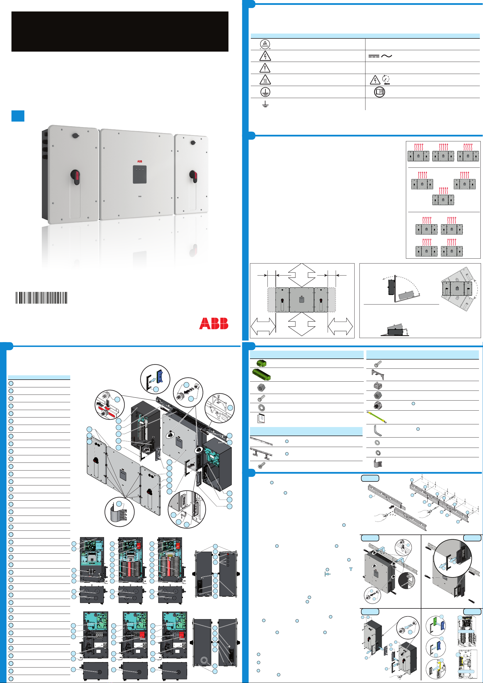
The following table shows the main components and connections available on the communication and control board. Each connection cable reaches the
communication board through signal conduit opening
34
35
.
See the product manual for details on the connections and functions available on the communication and control board.
Inverter
Ref. Manual
Ref. Description of the communication and control board
09
ON
3
2
1
OFF
S6
ON
3
2
1
OFF
S6
R46
R49
3
2
1
J1
J18
J7 J5
J8
X5
2
2
1
2
1
18
17
1
18
17
J6
J15
J22
J9 J10 J11 J12
J16
0
1
2
3
4
5
6
7
8
9
A
B
C
D
E
F
0
1
2
3
4
5
6
7
8
9
A
B
C
D
E
F
a04
a22
a23
a21
a05
a19a20
a14
a16
a09
a17a13 a02 a18
a12
a15
a11
J15 a02
Expansion board connector (optional)
A5 a04 SD Card socket
S8 - S9 a05 Country grid standard rotary switches
J5 - J6 a09 Multifunction relay connector (ALARM and AUX)
J7 a11 PC RS485 serial connection (PC); 5V auxiliary, remote ON/OFF,
and tachometer signal (wind version only)
S6 a12
RS-485 line 1 termination resistor
S5 a13
RS-485 line 2 termination resistor
J9 - J10 a14 RS-485 line 1 termination on RJ-45 connector (requires special wiring)
J8 a15 RS-485
line 1
communication board connector
J11 - J12 a16 RS-485 line 2 termination on RJ-45 connector (requires special wiring)
J16 a17 RS-485
line 2
communication board connector
S7 a18
Normal/service mode toggle switch
J22 a19 Inverter data memory card slot
X5 a20 Battery housing
J24 a21 AFD (Arc Fault Detector) housing
J1 a22 Grounding kit housing (optional)
15. Attach the two green/yellow ground wires to the attachment points
11
on each wiring box with the M6 lock washer and the M6 nut which are
shipped with the inverter (torque to 11Nm or 8ft-lb). Let the loose end
of the cable hang downwards. (FIG. 6)
16. Attach the two ground brackets
32
to the attachment points
37
on each
wiring box with the M6 at washer, M6 lock washer and the M6 hex screw
which are shipped with the inverter. Let the screws loose and not tightened.
The bracket is not symmetrical. When you install it in the attachment point
37
, make sure that the side with 2 holes is facing downwards. (FIG. 6)
17. Insert the rear studs
27
on top of rst wiring box into the bracket slots.
Then do the same with the other wiring box. This way, the wiring
boxes will be somewhat detached from the power module, so that
they won't interfere with the quick disconnects
23
. (FIG. 7)
18.
Attach the wiring box ground cable to the converter module with
the following hardware stackup: lock washer, ground cable, lock
washer and hex nut (torque to 11Nm or 8ft-lb).
(FIG. 7)
19.
Attach the power module to the wiring boxes one at a time by sliding
them horizontally onto the bracket
01
and make sure that the quick
disconnect
23
are correctly inserted.
(FIG. 7)
20.
Once coupling has been completed, the metal locking fork
07
must be
installed into the appropriate seats on the quick disconnects
23
. This
way, the wiring boxes get mounted to the power module.
21. Insert the stabilization fork
28
into the guides and block the screw
on the caged nuts previously mounted on the bracket.
22. Attach the ground brackets
32
in the mounting points
37
on the lower
side of the conversion module with the M6 at washer, M6 lock washer
and the M6 hex screw which are shipped with the inverter
(torque to
11Nm or 8ft-lb).
(FIG. 8)
23. Torque the two screws (one for each wiring box) on the 2 ground brack-
ets
32
. (FIG. 8)
23.
When wiring is complete,
close the key locks and
attach the front
covers
08
to the two wiring boxes (8 screws each).
24.
Install the 6 conducting springs
29
between the power module cover
03
and the wiring box covers, in the unpainted areas. (FIG. 9)
FIG 7
FIG 9
FIG 6
FIG 8
To prevent electrocution hazards, open and lock out the external AC disconnect switch before connecting the AC conductors, and any
time the AC wiring box cover is to be removed. Proper PPE is required.
Caution! Connect the ground before starting the grid connections.
AC output overcurrent protection is not provided with the inverter; it is the responsibility of the end user to provide overcurrent
protection for the AC output circuit. To reduce the risk of re, connect only to a circuit provided with an overcurrent protection in
accordance with the NEC (ANSI/NFPA 70). The inverter must be connected only to a dedicated branch circuit provided with the maximum
branch overcurrent protection device (OCPD) listed in the technical data sheet at the end of the document.
Size conductors per NEC Article 310 -- use 90°C wire only; conductors must be sized according to operating temperature range and
continuous current ratings. The AC grid wiring is connected through the inverter wiring box.
AC output wire must be UL listed wire rated minimum 600V.
Before connecting the inverter to the distribution grid, set the country standard using the two a05
rotary switches.
Depending on the country where the inverter is installed, there are different grid standard parameters.
The installer must be aware of the correct grid standard to be set.
The table shows the grid standard based on the position of the rotary switches a05.
The list of grid standards provided in the table is valid as of the publication date of this product’s QIG and
product manual.
Once the inverter is turned on, the grid settings can be modied only within the rst 24 hours of
operation. DC voltage is required.
Switch
ON
3
2
1
OFF
S6
ON
3
2
1
OFF
S6
R46
R49
3
2
1
J1
J18
J7 J5
J8
X5
2
2
1
2
1
18
17
1
18
17
J6
J15
J22
J9 J10 J11 J12
J16
0
1
2
3
4
5
6
7
8
9
A
B
C
D
E
F
0
1
2
3
4
5
6
7
8
9
A
B
C
D
E
F
a05
0
1
2
3
4
5
6
7
8
9
A
B
C
D
E
F
0
1
2
3
4
5
6
7
8
9
A
B
C
D
E
F
Country grid standard
0 0 NOT ASSIGNED
0 4 UL 1741 @ 277V Three Phase
3 4 USA - RULE21 THREE PHASE
3 B USA - Hawaii THREE PHASE
The inverter can be connected to the grid through a three-wire or a four-wire connection.
Standard and - A models AC wiring box:
- AC conductors (4AWG to 4/0AWG, copper or aluminum, torque to 14Nm / 10.3ft-lb) will be connected to a terminal block
17
inside the AC wiring box.
-B model AC wiring box:
- AC conductors (7AWG to 1/0AWG, copper, torque to 6Nm / 53in-lb) will connect to the AC disconnect switch
36
. The AC disconnect switch is designed for
copper wire. If aluminum wire is used, terminate the aluminum wire with a bi-metallic terminal.
The wires will be connected to the AC disconnect switch inside the AC wiring box.
AC cable installation:
- Remove the plug and install the conduit on the bottom side of the wiring box. There is one opening in the wiring box for AC conductors. If needed, a second
conduit opening may be added at the location silkscreened on the right-side chassis wall. Use a punch tool or appropriate saw to cut the opening.
- run the AC cables through the opening(s).
- Connect the ground cable to the protective earth (PE) connection point
20
.
-
Connect the grid conductors to the AC output terminal block
17
in the Standard / -A models or directly to the disconnect switch
36
in the -B wiring box.
- Give each wire a pull test to conrm the connection is secure.
- Conduit must be attached using liquid tight ttings to maintain Type 4 enclosure integrity.
- Set the switch on the AC lter board, based on the grid connection conguration: choose 3WIRES for WYE connection w/o N wire (L1+L2+L3+GND)
or 4WIRES for WYE connection with N wire (L1+L2+L3+Neutral+GND).
7.
Input connection (DC)
DCWB-2DCWB-1
CAUTION
ATTENTION
USE75 °C OR 90°C COPPER WIRE ONLY.Referto the instructionmanual
forsuitable wire size (AWG) and for tighteningtorque to be applied to
thewiring terminals.
UTILISEZSEULEMENT
CÂBLESEN
CUIVRE75 °C OU 90 °C. Consultez
le manuel d'instructionspour la
taille des ls approprié(AWG) et
pour couples de serrage à
appliqueraux bornes de câblage.
+IN
FUSE1
FUSE2
FUSE3
FUSE4
FUSE5
FUSE6
FUSE7
FUSE8
FUSE9
FUSE10
FUSE11
FUSE12
FUSE13
FUSE14
FUSE15
FUSE16
-IN
FUSE1
FUSE2
FUSE3
FUSE4
FUSE5
FUSE6
FUSE7
FUSE8
FUSE9
FUSE10
FUSE11
FUSE12
FUSE13
FUSE14
FUSE15
FUSE16
DCWB-2
DCWB-1
For -2 DC wiring box models only, the AFD performs a self-test when the system is started.
- If the self-test results are OK, the inverter will continue to AC grid connection.
- If a potential problem on the AFD board is detected, the self test will result in error E053.
Refer to the product manual (downloadable as described on the cover page) for troubleshooting suggestions.
During normal operation the input current is continually measured and analyzed.
- If a DC arc fault is detected during operation, the inverter is disconnects from AC grid and generates an E050 error code (readable through Aurora Manager software).
- Press and hold the AFD reset button on the left side of the DC wiring box for 3 seconds. This will clear the E050 error and restart the self test.
- If self-test results are OK, the inverter will reconnect to the AC grid; if the DC arc fault is still present, the self-test will result in error E053. Refer to the product manual
online for solutions. The AFD self-test can be manually started anytime using the following procedure:
1. Turn off the inverter (switching off both DC and AC switches),
2. Turn on both the DC and AC switches and wait for self-test result.
If the AFD trips frequently, it means arcs are occurring. Turn the inverter OFF and request service to do complete check of the system wiring, including all connections
and junction boxes, to locate the problem.
This inverter has been factory programmed to automatically disconnect from the utility distribution system in compliance with UL 1741 and IEEE 1547 specications. Default
voltage and frequency trip limit and trip time settings to comply with these standards are shown in table below. Aurora Manager software can be used to adjust Voltage and
Frequency Trip Limit and Trip Time Parameters according to Grid requirements of installation locale. Refer to product manual for instructions on how to use Aurora Manager
software.
Condition Utility source Max. time (sec)2at 60Hz before
cessation of current
Voltage (V) Frequency (Hz)
A < 0.50 Vnom (Fixed) Rated (60Hz) 0.16 (default)(Adj. Set Points 0.16 to 1.5s)
B 0.50 Vnom ≤ V < 0.88 Vnom (Adj. Set Points 55% to 88%) Rated (60Hz) 2 (Default)(Adj. Set Points 0.16 to 30 sec)
C1.10 Vnom < V < 1.2 Vnom (Adj. Set Points 110% to 120%) Rated (60Hz) 1 (Default)(Adj. Set Points 0.16 to 30 sec)
D1.2 Vnom ≤ V(Fixed) Rated (60Hz) 0.16 (Adj. 0.001 to 0.16s)
E Rated f>60.5Hz (Default)(Adj. 60.2 to 64.0 Hz) 0.16 (Default) (Adj. 0.16 to 300 sec)
F Rated f<59.3 Hz (Default)(Adj. 59.8 to 50.0 Hz) 0.16 (Default) (Adj. 0.16 to 300 sec)
G Rated f < 57.0 Hz 0.16 (Default) (Adj. 0.16 to 300 sec)
H Rated f > 63.0 Hz 0.16 (Default) (Adj. 0.16 to 300 sec)
The inverter can also be installed horizontally using the horizontal installation bracket. Horizontal installation instructions are described in the TRIO 50kW
product manual available at
www.abb.com/solarinverters (select appropriate country location on website).
11.
Grid support functions
The inverter is equipped with advanced grid support functionality that is useful to support reactive loads and also assist in reliable operation of the utility grid in the
presence of a large number of distributed energy generation sources.
The grid support functions that are equipped on this inverter are described in the following sections.
Aurora Manager software can be used to adjust grid parameters. Refer to product manual for instructions on how to use Aurora Manager software.
An RS485-USB
adapter (not included) is required to modify settings using the Aurora Manager software. The USB driver les and instructions for installation can be found online
at www.abb.com/solarinverters.
This QIG provides an overview of the available grid support functions. For complete details, refer to the technical manual at www.abb.com/solarinverters.
1.Voltage ride-through
This inverter provides parameters to respond to undervoltage and overvoltage events. The inverter is designed to operate normally within the specied operating range.
If voltage excursions occur, the inverter is designed to continue operating normally or cease to export power for a specied delay. Beyond this programmed delay, the
inverter disconnects from the grid in the event of an abnormal voltage condition. The parameters that control voltage ride-through can be accessed from Aurora Manager
software
2.Frequency ride-through
This inverter provides parameters to respond to underfrequency and overfrequency events. If frequency excursions occur, the inverter is designed to continue operating
normally for a specied delay. Beyond this programmed delay, the inverter disconnects from the grid in the event of an abnormal voltage condition.
3.Reactive power modes
This inverter is designed to export active as well as reactive power into the utility grid. The inverter provides several modes of operation for reactive power control and
are described below:
- Disable: This is the default setting. Under this setting, the inverter exports a power factor of 1.0.
- Fixed power factor control (Fixed cos-phi): In this mode, the operator can set the output power factor to a xed value. When enabled, Set percentage will appear on the
display, allowing the setting of the value of Cos-Phi as a percentage from 0.1 to 100.
- Power factor as function of output power (Std cosphi 0.9): In this mode, the inverter reduces the output power as a function of the output power at a given operating
point. The default curve can be modied using the Aurora Manager LITE software program, which can be downloaded from ABB‘s download center web page at http://
www.abb.com/abblibrary/DownloadCenter/.
- Dynamic Volt/VAR control (Std Q(U)): Under this mode, the level of reactive power exported by the inverter is a function of the operating grid voltage, also known as a
Volt/VAR curve. The default Volt/VAR curve can be modied using the Aurora Manager LITE software program.
4.Power reduction
This inverter offers two modes for active power reduction.
- Power limitation: When enabled from the Settings menu, this mode limits the active power that the inverter can export to the grid. The setting is specied as a
percentage of the rated power of the inverter, from 0% to 100% in steps of 1%.
- Frequency/Watt function (Set F Derating): In this mode, the inverter limits the active power as a function of the grid frequency. The default frequency/watt can be
modied using the Aurora Manager software.
5.Ramp controls
The inverter is designed to control the rate at which output power is increased, either at startup, or after a temporary low power condition on the PV array (such as fast
shading). The following ramp controls are provided on this inverter.
- Normal ramp: The normal ramp denes the maximum rate at which the inverter can increase the output power under normal operation. The normal ramp control limits
the dramatic uctuations in the output power in order to prevent instabilities on the utility grid.
- Slow ramp: The soft-start ramp denes the maximum rate at which the inverter can increase the output power when the inverter is rst starting up. This startup may
occur on a daily basis or when the inverter restarts after an abnormal grid event has ended.
8.
Connection of the communication and control signals