ABB CM-UFD.M21 Supplement

ABB Stotz-Kontakt GmbH
Hauptstr. 14-16
78132 Hornberg
Germany Document no. 1SVC 510 810 M0000 A1 (05/12)
CM-UFD.M21
(D) Kurzanleitung (Deutsch: Seite 1)
Netzeinspeiseüberwachungsrelais, CM Reihe
Hinweis: Diese Kurzanleitung enthält nicht sämtliche Detailinformationen zu allen
Typen der Produktreihe und kann auch nicht jeden Einsatzfall der Produkte
berücksichtigen. Alle Angaben dienen ausschließlich der Produktbeschreibung und sind
nicht als zugesicherte Eigenschaften im Rechtssinne aufzufassen. Weiterführende
Informationen und Daten erhalten Sie in den Katalogen und Datenblättern der Produkte,
über die örtliche ABB-Niederlassung sowie auf der ABB Homepage unter
http://www.abb.com. Technische Änderungen jederzeit vorbehalten. In Zweifelsfällen gilt
der deutsche Text.
Nur von einer entsprechend qualifizierten Fachkraft zu installieren. Dabei
landesspezifische Vorschriften (z.B. VDE, etc.) beachten. Vor der Installation
diese Betriebs- und Montageanleitung sorgfältig lesen und beachten. Die
Geräte sind wartungsfreie Einbaugeräte.
(GB) Short guide (English: page 9)
Grid feeding monitoring relay, CM range
Note: This short guide cannot claim to contain all detailed information of all types of this
product range and can even not consider every possible application of the products. All
statements serve exclusively to describe the product and have not to be understood as
assured characteristics with legal force. Further information and data is obtainable from
the catalogues and data sheets of this product, from the local ABB sales organisations
as well as on the ABB homepage http://www.abb.com. Subject to change without prior
notice. The German text applies in cases of doubt.
The device must be installed by qualified persons only and in accordance with
the specific national regulations (e.g., VDE, etc.). Before installing this unit,
read these operating and installation instructions carefully and completely. The
devices are maintenance-free chassis-mounted units.

Document no. 1SVC 510 810 M0000 A1 1 / 16
Deutsch
- NA-Schutz nach VDE-AR-N 4105, Erzeugungsanlagen am Niederspannungsnetz
- zum Einsatz in Erzeugungsanlagen am Mittelspannungsnetz nach BDEW
- mit zuschaltbarer Vektorsprungerkennung
Anzeige- und Bedienelemente
Taster Test
kurz
drücken
Ausgangsrelais fallen sofort ab. Sind Y1+Y2 angeschlossen und die
Rückmeldung aktiviert, wird bis zum nächsten Druck auf eine Taste die
Auslösezeit angezeigt
LEDs Frequenz / Spannung Schwellwert unter- / überschritten (rot)
AN, 8AL 8oder 8AL M8 Schwellwert unter- / überschritten
BLINKT, 8AL 8oder 8AL M8Rückfallverzögerung 8dof 8läuft ab
LED Vektorsprung (Δφ, rot)
AN, 8AL 8Schwellwert Vektorsprung überschritten
BLINKT, 8AL 8Rückfallverzögerung 8dof 8läuft ab
LEDs Relaiszustand (gelb)
AUS Relais abgefallen
AN Relais angezogen
Digitalanzeige 4-stellig (rot)
je nach Programm Anzeige aktuelle Spannung, Frequenz, Vektorsprung, Mittelwert
Anzeige von Alarmmeldungen z.B. 8AL 8, 8aL M8
Anzeige von Fehlern mit Fehlercode z. B. 8Err98
LED Time (gelb)
AN Im Display wird eine Zeit angezeigt
Hinterster Dezimalpunkt (rot)
AUS Anzeigemodus
AN Menümodus
Blinkt Parametriermodus
Taster Set / Reset (im Anzeigemodus, Normalzustand)
Kurz drücken Anzeige nächster Messwert / Alarmzähler
Betätigung für > 2 s Reset, Zurücksetzen von Fehlermeldungen
Betätigung für > 4 s Anzeige Programm z. B. 8Pr 18
Betätigung für > 10 s Anzeige der Firmwareversion z. B. 80-018

Document no. 1SVC 510 810 M0000 A1 2 / 16
Taster Up / Down (im Anzeigemodus, Normalzustand)
kurz drücken
Wechsel in den Menümodus, Anzeige Alarmspeicher (Down) /
Alarmsummenzeit (Up), zusätzliches drücken der Taste Set für ≥2 s
löscht die gespeicherten Werte
Betätigung für
> 2 s
Anzeige des MAX (Up) / MIN (Down) - Messwertes, zusätzliches
drücken der Taste Set für ≥2 s löscht alle gespeicherten Werte
LEDs Messwertzuordnung (gelb)
LEDs Messwert
Lx und N AN Spannungswert (L1 gegen N, L2 gegen N, L3 gegen N)
Lx und Ly AN Spannungswert (L1 gegen L2, L2 gegen L3, L1 gegen L3)
Lx BLINKT schnell Vektorsprung (L1, L2, L3)
L1 BLINKT Frequenz
plombierbarer Taster + LED
Betätigung für > 2 s Sperren / entsperren
LED rot Einstellungen und Simulationsmodus sind gesperrt,
bei Einstellversuch wird 3 s 8LOc 8angezeigt
LED grün Einstellungen ändern und simulieren möglich
Beschreibung der Anschlüsse
A1 und A2 Bemessungssteuerspeisespannung Us, siehe Technische Daten
(Polarität beliebig)
11, 12, 14; 21, 22, 24 Relais K1 und K2
potentialfreier Öffner
Kontakt geschlossen, Vektorsprung wird nicht ausgewertet
(Unterdrückung)
Δφ1 – Δφ2
Enable-Eingang, wird nur
zur
Vektorsprungerkennung
benötigt Kontakt offen, Vektorsprung wird ausgewertet
potentialfreier Schließer- oder Öffner-Kontakt, selbstlernend beim
Einschalten
Y0, Y1, Y2
Eingänge
Rückmeldekontakte Einschaltzeit Kuppelschalter unter 8trel.8einstellen / wenn nicht
verwendet, ausschalten
VQSpeisespannung für Digitalausgänge, max. 27 V DC
Q1…Q4 Digitalausgang Über-/Unterspannung/-frequenz
Q5 Digitalausgang Error, zusätzlich in Pr 3 + 4 zweiter Schwellwert
L1, L2, L3, N Phase L1, L2, L3 und Neutralleiter
Wichtige Hinweise
In der Zuleitung in der Nähe des Gerätes (leicht erreichbar) muss ein
als Trennvorrichtung gekennzeichneter Schalter, sowie ein Überstrom-
Schutzorgan (Bemessungsstrom ≤6 A) angebracht sein.
Achtung!
Bemessungssteuerspeisespannung dem seitlichen Typenschild am Gerät
entnehmen!
!
!

Document no. 1SVC 510 810 M0000 A1 3 / 16
WARNUNG
Gefährliche elektrische Spannung!
Kann zu elektrischem Schlag und Verbrennungen führen.
Vor Beginn der Arbeiten Anlage und Gerät spannungsfrei schalten.
Montage
Das Gerät kann befestigt werden:
Verteilereinbau oder Schaltschrank auf 35 mm Tragschiene nach EN 60715
Anschlussplan

Document no. 1SVC 510 810 M0000 A1 4 / 16
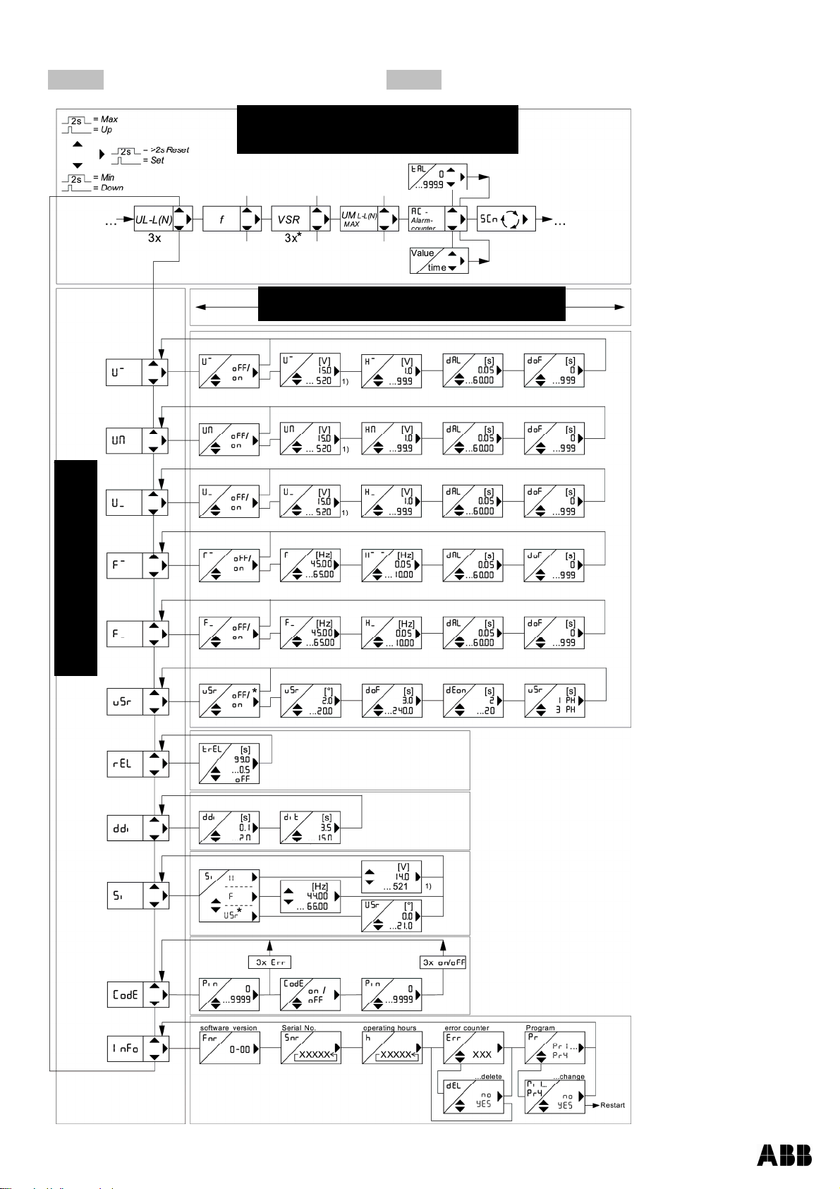
Programm einstellen
Entsprechend der Anwendung, muss am CM-UFD.M21 das passende Programm eingestellt werden. Ist
das CM-UFD.M21 plombiert/gesperrt (rote LED leuchtet) muss zuerst die Plombierung deaktiviert
werden.
Pr Anschluss Schwellwerte Spannung
*1 3 AC mit N
230 V
2 3 AC ohne N
Niederspannung
1x Überspannung, 1x Unterspannung
1x Überfrequenz, 1x Unterfrequenz
10 min Mittelwert, 1x Vektorsprung
400 V
3 3 AC mit N 57,7 V
4 3 AC ohne N 100 V
5 3 AC mit N 230V
6 3 AC ohne N
Mittelspannung
2x Überspannung, 2x Unterspannung
2x Überfrequenz, 2x Unterfrequenz
10 min Mittelwert, 1x Vektorsprung 400V
* Werkseinstellung
Einstellvorgang:
falls vorhanden, Plombierung entfernen (nur autorisierte Person)
Steuerspeisespannung an A1-A2 anlegen
Tasterabdeckung leicht anheben und um 180° drehen
Kleinen blauen Taster durch kräftiges Drücken auf die Tasterabdeckung (LED beginnt zu
blinken) solange betätigen bis - LED grün leuchtet
Taste 1x drücken Anzeige 8Info.8
Taste 5x drücken Anzeige 8Pr 1.8
Programm mit den Tasten einstellen
Taste 1x drücken Anzeige 8no.8
Taste 1x drücken Anzeige 8yes.8
Taste drücken
Gerät macht einen Reset und startet mit dem neu gewählten Programm
Tipp: Bei einem Programmwechsel werden alle Parameter auf „Werkseinstellung“ des gewählten
Programms zurückgesetzt (siehe Tabelle „ Werkseinstellungen“). Ändern Sie die Parameter
erst, nachdem Sie das richtige Programm gewählt haben.
Technische Daten
Bemessungssteuerspeisespannung Us:24-240 V AC/DC, DC / 40-70 Hz, <5 VA
Toleranz -15…+10 %
Ausgangsrelais: 2 Wechsler
Max. Schaltspannung 400 V AC
Konventioneller thermischer Strom Ith 6 A
Einschaltstrom (bei 10 % ED) 25 A max. 4 s / 50 A max. 1 s
Bemessungsbetriebsstrom Ie(AC15) 230 V AC / 1,5 A
Kurzschlussschutz, max. Schmelzsicherung gG/gL 6 A
Mechanische Lebensdauer 30 x 106Schaltspiele
Elektrische Lebensdauer 1 x 10⁶Schaltspiele bei AC12, 230 V, 6 A
Ausgangskreis – Transistorausgänge Q1-Q5
Betriebsspannung VQ4,5-27 V DC
Max. Stromaufnahme Q1…Q5 20 mA / Ausgang
Eingangskreis – Rückmeldekontakte Y0 – Y1/2
Leerlaufspannung an den Steuereingängen 15-35 V DC
Rückmeldezeit Kuppelschalter 0,5-99,0 s einstellbar
Technische Änderungen vorbehalten

Document no. 1SVC 510 810 M0000 A1 5 / 16
Bedienungsdiagramme
8Pr 183AC mit N, gem. VDE-AR-N 4105 8Pr 283AC ohne N, gem. VDE-AR-N 4105
[ ] = Einheit
Up/Down gleichzeitig drücken, setzt
Werte auf kleinsten Wert.
Code-Reset = bei Anlegen der
Steuerspeisepannung 2 s Taster Set
drücken (Pin = 504)
Anzeigemodus
Parametriermodus
Menümodus
1) 3AC+N = 300 V

Document no. 1SVC 510 810 M0000 A1 6 / 16
Werkseinstellung und Firmwareversion
Beim Programmwechsel werden alle Parameter auf Werkseinstellung zurückgesetzt.
Werkseinstellung
Niederspannung Mittelspannung
3AC+N
230V
3AC
400V
3AC+N
57,7V
3AC
100V
3AC+N
230V
3AC
400V
Menü-
punkt Parameter / Einheit
Pr1 *Pr2 Pr3 Pr4 Pr5 Pr6
u,, Alarm on/off -
-
on
on
on
on
u,, Überspannung V -
-
66.4
115
264
458
H,, Hysterese V -
-
1.0
1.0
3.0
3.0
dal Ansprechverzögerungszeit s -
-
0.10
0.10
0.10
0.10
U,,
dof Rückfallverzögerungszeit s -
-
60
60
60
60
u, Alarm on/off on
on
On
on
on
on
u, Überspannung V 264
458
62.3
108
249
430
H, Hysterese V 5.0
5.0
1.0
1.0
3.0
3.0
dal Ansprechverzögerungszeit s0.10
0.10
60.00
60.00
60.00
60.00
U,
dof Rückfallverzögerungszeit s 60
60
60
60
60
60
UM Alarm on/off on
on
Off
Off
off
Off
UM Überspannung V 253
438
253
438
253
438
HM Hysterese V 3.0
3.0
3.0
3.0
3.0
3.0
dal Ansprechverzögerungszeit s 0.10
0.10
0.10
0.10
0.10
0.10
UM
dof Rückfallverzögerungszeit s 60
60
60
60
60
60
u_ Alarm on/off on
on
On
On on
on
u_ Unterspannung V 184
318
46.2
80.0
184
318
H_ Hysterese V 5.0
5.0
1.0
1.0
3.0
3.0
dal Ansprechverzögerungszeit s 0.10
0.10
2.70
2.70
2.70
2.70
U_
dof Rückfallverzögerungszeit s 60
60
60
60
60
60
u__ Alarm on/off -
-
Off
Off
off
Off
u__ Unterspannung V -
-
26.0
45.0
104
180
H__ Hysterese V -
-
1.0
1.0
2.0
2.0
dal Ansprechverzögerungszeit s -
-
0.30
0.30
0.30
0.30
U__
dof Rückfallverzögerungszeit s -
-
60
60
60
60
F,, Alarm on/off -
-
off
Off
off
Off
F,, Überfrequenz Hz -
-
51.50
51.50
51.50
51.50
H,, Hysterese Hz -
-
1.45
1.45
1.45
1.45
dal Ansprechverzögerungszeit s -
-
0.10
0.10
0.10
0.10
F,,
dof Rückfallverzögerungszeit s -
-
60
60
60
60
F, Alarm on/off on
on
on
on
on
on
F, Überfrequenz Hz 51.50
51.50
51.50
51.50
51.50
51.50
H, Hysterese Hz 1.45
1.45
1.45
1.45
1.45
1.45
dal Ansprechverzögerungszeit s 0.10
0.10
0.10
0.10
0.10
0.10
F,
dof Rückfallverzögerungszeit s 60
60
60
60
60
60

Document no. 1SVC 510 810 M0000 A1 7 / 16
Werkseinstellung
Niederspannung Mittelspannung
3AC+N
230V
3AC
400V
3AC+N
57,7V
3AC
100V
3AC+N
230V
3AC
400V
Menü-
punkt Parameter / Einheit
Pr1 *Pr2 Pr3 Pr4 Pr5 Pr6
F_ Alarm on/off on
on
on
on
on
on
F_ Unterfrequenz Hz 47.50
47.50
47.50
47.50
47.50
47.50
H_ Hysterese Hz 1.00
1.00
1.00
1.00
1.00
1.00
dal Ansprechverzögerungszeit s 0.10
0.10
0.10
0.10
0.10
0.10
F_
dof Rückfallverzögerungszeit s 60
60
60
60
60
60
F__ Alarm on/off -
-
off
off
off
off
F__ Unterfrequenz Hz -
-
47.50
47.50
47.50
47.50
H__ Hysterese Hz -
-
1.00
1.00
1.00
1.00
dal Ansprechverzögerungszeit s -
-
0.10
0.10
0.10
0.10
F__
dof Rückfallverzögerungszeit s -
-
60
60
60
60
vsr Alarm on/off off
off
off
off
off
off
vsr Vektorsprung °10.0
10.0
10.0
10.0
10.0
10.0
dof Rückfallverzögerungszeit s 3
3
3
3
3
3
dEon Unterdrückungszeit s 2
2
3
3
3
3
vsr
vsr Phasenanzahl 3ph
3ph
3ph
3ph
3ph
3ph
rEL trEL Schaltzeit Y1,Y2 s 5.0
5.0
off
off
off
off
ddi Displayverzögerung s 0.5
0.5
0.5
0.5
0.5
0.5
ddi dit Anzeigedauer SCn s 3.5
3.5
3.5
3.5
3.5
3.5
U Spannung V230
400
57.7
100
230
400
F Frequenz Hz
50.00
50.00
50.00
50.00
50.00
50.00
Si
vsr Vektorsprung °0.0
0.0
0.0
0.0
0.0
0.0
CodE pin Pincode
504
504
504
504
504 504
fnr Firmwareversion
0-01
0-01
0-01
0-01
0-01
0-01
snr Seriennummer xxxxx xxxxx xxxxx xxxxx xxxxx xxxxx
h Betriebsstunden h xxxxx xxxxx xxxxx xxxxx xxxxx xxxxx
err Fehlerzähler xxx xxx xxx xxx xxx xxx
Info
Pr Programm
1
2
3
4
5 6
* ab Werk eingestellt
Anzeige des Programms: 8Info88Pr 88 oder beim Einschalten
Anzeige der Firmwareversion: 8Info88fnr 8
Schutzfunktionen, Werkseinstellungen nach VDE-AR-N 4105 Abs. 6.5.2
Spannungssteigerungsschutz U>> 8U, 81,15 Un 100 ms
Spannungssteigerungsschutz U> 8UM 81,1 Un 100 ms
Spannungsrückgangsschutz U< 8U_ 80,8 Un 100 ms
Frequenzsteigerungsschutz f> 8f, 851,5 Hz 100 ms
Frequenzrückgangsschutz f< 8f_ 847,5 Hz 100 ms

Document no. 1SVC 510 810 M0000 A1 8 / 16
Fehlerbehebung
Fehler Ursache Abhilfe
8EEEE8oder 8-EEE8
erscheint in der
Anzeige
Gemessene Spannung,
Frequenz oder der
Vektorsprung ist zu groß
bzw. zu klein,
Messbereich beachten
8Err48erscheint in
der Anzeige
Zu hohe interne
Messwertabweichung der
beiden Messkanäle
8Err58erscheint in
der Anzeige Fehler interne Regelung
8Err68erscheint in
der Anzeige
Kommunikationsfehler
interne Schnittstelle
Reset durchführen
Steuerspeisespannung für >5 s
unterbrechen
8Err78erscheint in
der Anzeige + LED
des fehlerhaften
Ausgangskreises
leuchtet
Fehler Rückmeldekontakte
Rückmeldekontakte nicht
angeschlossen
- 8trel.88off8einstellen
Rückmeldekontakte angeschlossen
- richtigen Anschluss prüfen
- Einschaltzeit des Kuppelschalters
unter 8trel.8einstellen
- Reset durchführen Steuerspeise-
spannung für >5 s unterbrechen
8Err88erscheint in
der Anzeige
Hysteresefehler:
Überschneidung der
Rückschaltpunkte
Oberer Schwellwert muss größer als
unterer Schwellwert sein, Schwellwerte
überprüfen
8Err98erscheint in
der Anzeige Parameterfehler Werkseinstellung neu laden, siehe
Programm einstellen
Im Display läuft eine
Zeit ab
Immer wenn eine
Rückfallverzögerungszeit
8dof 8abläuft, wird diese in
der Anzeige herunter-
gezählt (kürzeste zuerst)
Warten bis die Zeit abgelaufen ist (es
können je nach Einstellung auch
mehrere Zeiten nacheinander
ablaufen)
Gerät lässt sich nicht
parametrieren / nur
die Schwellwerte
lassen sich
parametrieren
Codesperre/Plombierung
aktiv
Bei Problemen mit der Codesperre
(Pin vergessen) kann die Sperre
ausgeschaltet und die Pin auf 504
zurückgesetzt werden, indem beim
Netzeinschalten die Taste gedrückt
wird bis in der Anzeige 8Code8/
off8erscheint.
Unplausible
Spannungswerte
Pr mit N gewählt, aber N
nicht angeschlossen Pr ohne N wählen oder N anschließen
8Loc 8erscheint in
der Anzeige Plombierung ist aktiv Siehe Programm einstellen
8Code8erscheint in
der Anzeige Codesperre ist aktiv Siehe Codesperre

Document no. 1SVC 510 810 M0000 A1 9 / 16
English
- NA-protection according to VDE-AR-N 4105, power generators at the low voltage grid
- for use in power generators at the medium voltage grid according to BDEW
- with selectable vector shift detection
Operating controls
Test button
Press
shortly
Output relays de-energize immediately. If Y1+Y2 are connected and the feedback
signal is activated, the tripping time is displayed as long as no button is actuated
LEDs Frequency / voltage, above / below threshold (red)
ON, 8AL 8or 8AL M8 Above / below threshold
Flashing, 8AL 8or 8AL M8OFF-delay 8dof 8active
LED Vector shift (Δφ, red)
ON, 8AL 8Threshold value for vector shift exceeded
Flashing, 8AL 8OFF-delay 8dof 8active
LEDs Relay status (yellow)
OFF Relays de-energized
ON Relays energized
Digital display 4-digit (red)
Depending on program, display of current voltage, frequency, vector shift, average value
Display of alarm message 8AL 8, 8aL M8
Display of error with error code e.g. 8Err98
LED Time (yellow)
ON A time is displayed
Backmost decimal point (red)
OFF Display mode
ON Menu mode
Flashing Configuration mode
Set / Reset button (in display mode, normal state)
Press shortly Display of next measured value / alarm counter
Press for > 2 s Reset, quit error messages
Press for > 4 s Display of program, e.g. 8Pr 18
Press for > 10 s Display of firmware version, e.g. 80-018

Document no. 1SVC 510 810 M0000 A1 10 / 16
Up / Down button (in display mode, normal state)
Press shortly
Change to the menu mode, display of alarm memory (Down) /
cumulative time of alarms (Up), additional pushing of Set button for ≥2 s
makes a reset of the stored values
Press for > 2 s Display of MAX (Up) / MIN (Down) measured values, additional pushing
of Set button for ≥2 s deletes the stored values
LEDs Allocation of the measured value (yellow)
LEDs Measured value
Lx and N ON Voltage (L1 against N, L2 against N, L3 against N)
Lx and Ly ON Voltage (L1 against L2, L2 against L3, L1 against L3)
Lx flashing quickly Vector shift (L1, L2, L3)
L1 flashing Frequency
Sealable button + LED
Press for > 2 s Lock / Unlock
LED red Settings and simulation mode are locked,
in case of setting attempts 8LOc 8is displayed for 3 s
LED green Setting and simulation enabled
Description of the connections
A1 and A2 Rated control supply voltage Us, see Technical Data
(any polarity)
11, 12, 14; 21, 22, 24 Relay K1 and K2
Volt-free n/c contact
Contact closed, no evaluation of vector shift (suppression)
Δφ1 – Δφ2
Enable-input, needed only
for vector shift detection Contact open, evaluation of vector shift
Volt-free n/o or n/c contact, self-learning when switching on
Y0, Y1, Y2
Inputs, feedback contacts Adjust the turn-on time of the section switch under 8trel.8/ switch-off
if not used
VQSupply voltage for digital outputs, max. 27 V DC
Q1…Q4 Digital output over-/undervoltage/-frequency
Q5 Digital output Error, in Pr 3 + 4 additionally the 2nd threshold value
L1, L2, L3, N Phase L1, L2, L3 and neutral conductor
Important notice
In the supply line in the vicinity of the device (easily accessible), a switch marked
as disconnecting device as well as an overcurrent protection element (rated current
≤6 A) have to be provided.
Attention!
For the rated control supply voltage, see label at the side of the unit!
!
!

Document no. 1SVC 510 810 M0000 A1 11 / 16
WARNING
Hazardous electrical voltage!
Can lead to electric shock and burns.
Before starting work, switch plant and device voltage-free.
Mounting
The device can be mounted:
Distribution panel or control panel on 35 mm rail according to EN 60715
Connection diagram

Document no. 1SVC 510 810 M0000 A1 12 / 16
Program setup
The suitable program must be set on the CM-UFD.M21 in accordance with the application. If the
CM-UFD.M21 is sealed/locked (red LED lightning), sealing has to be deactivated first.
Pr Connection Threshold values Voltage
*1 3 AC with N
230 V
2 3 AC w/o N
Low voltage
1x overvoltage, 1x undervoltage
1x overfrequency, 1x underfrequency
10 min average value, 1x vector shift
400 V
3 3 AC with N 57.7 V
4 3 AC w/o N 100 V
5 3 AC with N 230V
6 3 AC w/o N
Medium voltage
2x overvoltage, 2x undervoltage
2x overfrequency, 2x underfrequency
10 min average value, 1x vector shift 400V
* default setting
Adjustment process:
If present, remove seal (only authorised person)
Apply control supply voltage at A1-A2
Slightly lift the button cover and turn 180°
Actuate the small blue button by strong pressing on the button cover (LED starts flashing)
until the green LED is lightning.
Press button 1x Display 8Info.8
Press button 5x Display 8Pr 1.8
Set the program with the buttons
Press button 1x Display 8no.8
Press button 1x Display 8yes.8
Press button
Device resets and starts with the newly selected program
Hint: When changing programs, all parameters of the selected program are reset to “default settings“
(see table „Default settings“). Only change the parameters after having selected the correct
program.
Technical data
Rated control supply voltage Us:24-240 V AC/DC, DC / 40-70 Hz, <5 VA
Tolerance -15…+10 %
Output relays: 2 c/o contacts
Max. switching voltage 400 V AC
Conventional thermal current Ith 6 A
Inrush current (at 10 % ED) 25 A max. 4 s / 50 A max. 1 s
Rated operational current Ie(AC15) 230 V AC / 1.5 A
Fuse rating to achieve short-ciruit protection max. gG/gL 6 A
Mechanical lifetime 30 x 106switching cycles
Electrical lifetime 1 x 10⁶switching cycles at AC12, 230 V, 6 A
Output voltage - transistor outputs Q1-Q5
Operational voltage VQ4.5-27 V DC
Max. current consumption Q1…Q5 20 mA / output
Input circuit - feedback contacts Y0 – Y1/2
No-load voltage at the control inputs 15-35 V DC
Feedback time section switch 0.5-99.0 s selectable
Subject to change without prior notice

Document no. 1SVC 510 810 M0000 A1 13 / 16
Control chart
8Pr 183AC with N, acc. to VDE-AR-N 4105 8Pr 283AC w/o N, acc. to VDE-AR-N 4105
[ ] = Unit
Pressing buttons Up/Down
simultaneously, sets the
values to the smallest one.
Code-Reset = Press button Set 2 s
while applying control supply voltage
Display mode
Confi
g
uration mode
Menu mode
1) 3AC+N = 300 V

Document no. 1SVC 510 810 M0000 A1 14 / 16
Default settings and firmware version
When changing programs, all parameters are reset to the default settings.
Default settings
Low voltage Medium voltage
3AC+N
230V
3AC
400V
3AC+N
57.7V
3AC
100V
3AC+N
230V
3AC
400V
Menu
point Parameter / Unit
Pr1 *Pr2 Pr3 Pr4 Pr5 Pr6
u,, Alarm on/off -
-
on
on
on
on
u,, Overvoltage V -
-
66.4
115
264
458
H,, Hysteresis V -
-
1.0
1.0
3.0
3.0
dal ON-delay s -
-
0.10
0.10
0.10
0.10
U,,
dof OFF-delay s-
-
60
60
60
60
u, Alarm on/off on
on
On
on
on
on
u, Overvoltage V 264
458
62.3
108
249
430
H, Hysteresis V 5.0
5.0
1.0
1.0
3.0
3.0
dal ON-delay s0.10
0.10
60.00
60.00
60.00
60.00
U,
dof OFF-delay s60
60
60
60
60
60
UM Alarm on/off on
on
Off
Off
off
Off
UM Overvoltage V 253
438
253
438
253
438
HM Hysteresis V 3.0
3.0
3.0
3.0
3.0
3.0
dal ON-delay s 0.10
0.10
0.10
0.10
0.10
0.10
UM
dof OFF-delay s 60
60
60
60
60
60
u_ Alarm on/off on
on
On
On
on
on
u_ Undervoltage V 184
318
46.2
80.0
184
318
H_ Hysteresis V 5.0
5.0
1.0
1.0
3.0
3.0
dal ON-delay s 0.10
0.10
2.70
2.70
2.70
2.70
U_
dof OFF-delay s60
60
60
60
60
60
u__ Alarm on/off -
-
Off
Off
off
Off
u__ Undervoltage V -
-
26.0
45.0
104
180
H__ Hysteresis V -
-
1.0
1.0
2.0
2.0
dal ON-delay s -
-
0.30
0.30
0.30
0.30
U__
dof OFF-delay s -
-
60
60
60
60
F,, Alarm on/off -
-
off
Off
off
Off
F,, Overfrequency Hz -
-
51.50
51.50
51.50
51.50
H,, Hysteresis Hz -
-
1.45
1.45
1.45
1.45
dal ON-delay s -
-
0.10
0.10
0.10
0.10
F,,
dof OFF-delay s-
-
60
60
60
60
F, Alarm on/off on
on
on
on
on
on
F, Overfrequency Hz 51.50
51.50
51.50
51.50
51.50
51.50
H, Hysteresis Hz 1.45
1.45
1.45
1.45
1.45
1.45
dal ON-delay s 0.10
0.10
0.10
0.10
0.10
0.10
F,
dof OFF-delay s 60
60
60
60
60
60

Document no. 1SVC 510 810 M0000 A1 15 / 16
Default settings
Low voltage Medium voltage
3AC+N
230V
3AC
400V
3AC+N
57.7V
3AC
100V
3AC+N
230V
3AC
400V
Menu
point Parameter / Unit
Pr1 *Pr2 Pr3 Pr4 Pr5 Pr6
F_ Alarm on/off on
on
on
on
on
on
F_ Underfrequency Hz 47.50
47.50
47.50
47.50
47.50
47.50
H_ Hysteresis Hz 1.00
1.00
1.00
1.00
1.00
1.00
dal ON-delay s 0.10
0.10
0.10
0.10
0.10
0.10
F_
dof OFF-delay s 60
60
60
60
60
60
F__ Alarm on/off -
-
off
off
off
off
F__ Underfrequency Hz -
-
47.50
47.50
47.50
47.50
H__ Hysteresis Hz -
-
1.00
1.00
1.00
1.00
dal ON-delay s -
-
0.10
0.10
0.10
0.10
F__
dof OFF-delay s -
-
60
60
60
60
vsr Alarm on/off off
off
off
off
off
off
vsr Vector shift °10.0
10.0
10.0
10.0
10.0
10.0
dof OFF-delay s 3
3
3
3
3
3
dEon Suppression time s 2
2
3
3
3
3
vsr
vsr Number of phases 3ph
3ph
3ph
3ph
3ph
3ph
rEL trEL Switching time Y1,Y2 s 5.0
5.0
off
off
off
off
ddi Display delay s 0.5
0.5
0.5
0.5
0.5
0.5
ddi dit Display duration SCn s 3.5
3.5
3.5
3.5
3.5
3.5
U Voltage V230
400
57.7
100
230
400
F Frequency Hz
50.00
50.00
50.00
50.00
50.00
50.00
Si
vsr Vector shift °0.0
0.0
0.0
0.0
0.0
0.0
CodE pin Pin code
504
504
504
504
504 504
fnr Firmware version
0-01
0-01
0-01
0-01
0-01
0-01
snr Serial number xxxxx xxxxx xxxxx xxxxx xxxxx xxxxx
h Operating hours h xxxxx xxxxx xxxxx xxxxx xxxxx xxxxx
err Error counter xxx xxx xxx xxx xxx xxx
Info
Pr Program
1
2
3
4
5 6
* factory preset
Display of the program: 8Info88Pr 88 or when switching on
Display of the firmware version: 8Info88fnr 8
Protective functions, default settings according to VDE-AR-N 4105 section 6.5.2
Voltage increase protection U>> 8U, 81.15 Un 100 ms
Voltage increase protection U> 8UM 81.1 Un 100 ms
Voltage decrease protection U< 8U_ 80.8 Un 100 ms
Frequency increase protection f> 8f, 851.5 Hz 100 ms
Frequency decrease protection f< 8f_ 847.5 Hz 100 ms

Document no. 1SVC 510 810 M0000 A1 16 / 16
Troubleshooting
Error Cause Remedy
8EEEE8or 8-EEE8
appears in the display
Measured voltage,
frequency or the vector shift
is too large or too small
Consider the measuring range
8Err48
appears in the display
Too high internal
measurement deviation of
the two measuring channels
8Err58
appears in the display Error internal regulation
8Err68
appears in the display
Communication error
internal interface
Perform a reset
interrupt the control supply voltage
for >5 s
8Err78appears in
the display + LED
of the faulty output
circuit is lightning
Error feedback contacts
Feedback contacts not connected
- set 8trel.88off8
Feedback contacts connected
- check the correct connection
- Adjust the turn-on time of the section
switch under 8trel.8
- Perform a reset interrupt the
control supply voltage for >5 s
8Err88
appears in the display
Hysteresis error:
overlapping of the release
points
Upper threshold value must be higher
than the lower threshold value, check
the threshold values
8Err98
appears in the display Configuration error Reset to factory settings, see “Program
setup”
A time expires in the
display
If a OFF-delay 8dof 8is
active, the time runs down
in the display (the shortest
one first)
Wait until the time is complete
(depending on the setting, several
times may elapse one after the other)
Device cannot be
configured / only the
threshold values can
be configured
Code lock / Sealing
activated
When having problems with the code
lock (Pin forgotten), the lock can be
deactivated and the pin can be reset to
504 , by pressing the button until
8Code8/ off8is shown in the
display, while switching on the control
supply voltage
Implausible voltage
values
Pr selected with N, but N
not connected Select Pr without N or connect N
8Loc 8
appears in the display Sealing is active See „Program setup“
8Code8
appears in the display Code lock is active See „Code lock“
Table of contents
Languages:
Other ABB Measuring Instrument manuals

ABB
ABB WaterMaster User manual

ABB
ABB SR100A User manual

ABB
ABB CB-2000 User manual

ABB
ABB ACF5000 User manual

ABB
ABB GLA131 Series User manual

ABB
ABB Endura AZ20 series User manual

ABB
ABB 10D1475 User manual

ABB
ABB FMT200-ECO2 User manual

ABB
ABB CoriolisMaster FCM2000 Training manual

ABB
ABB AK101 User manual

ABB
ABB ISL-C 600 User manual

ABB
ABB ProcessMaster FEP630 series User manual

ABB
ABB ControlMaster CM15 User manual

ABB
ABB AX400 Series User manual

ABB
ABB EL3060 Series User guide

ABB
ABB 8241 User manual

ABB
ABB Aztec 600 User manual

ABB
ABB AX411 User manual

ABB
ABB NETA-21 User manual

ABB
ABB i-bus EIB Delta-Meter User manual