ABB EV3 User manual

1/21
—
ENERGY METER
EV3
User Manual
EV3
User Manual
Document ID: 9AKK107991A1347
Revision: A
2020-12-01

2/21
Disclaimer
The information in this document is subject to change without notice and
should not be construed as a commitment by ABB Spa. ABB Spa assumes
no responsibility for any errors that may appear in this document.
In no event shall ABB Spa be liable for direct, indirect, special, incidental
or consequential damages of any nature or kind arising from the use of
this document, nor shall ABB Spa be liable for incidental or consequential
damages arising from use of any software or hardware described in this
document.
Copyrights
This document and parts thereof must not be reproduced or copied
without written permission from ABB Spa, and the contents thereof must
not be imparted to a third party nor used for any unauthorized purpose.
The software or hardware described in this document is furnished under
a license and may be used, copied, or disclosed only in accordance with
the terms of such license.
© Copyright 2020 ABB Spa. All rights reserved.
Trademarks
ABB Spa is a registered trademark of the ABB Group. All other brand or
product names mentioned in this document may be trademarks or
registered trademarks of their respective holders.
Contact
ABB SpA
Via Dell'industria, 18
20009 – Vittuone – Milano
Italy
Tel. +39 02 2415 0000

3/21
Table of Contents
1General Information .................................................................................................................. 4
1.1 Responsibility .............................................................................................................................. 4
1.2 Common safety instructions.................................................................................................... 4
1.3 Service and warranty instructions.......................................................................................... 4
1.4 Disposal (product end of life information) ........................................................................... 4
1.5 Environment................................................................................................................................. 5
1.6 Service and Warranty ................................................................................................................. 5
1.7 Cyber Security Disclaimer......................................................................................................... 5
1.8 Symbols......................................................................................................................................... 6
2Technical data .............................................................................................................................7
2.1 Abbreviations................................................................................................................................7
2.2 Technical specifications .............................................................................................................7
2.2.1 Technical Standards ................................................................................................. 9
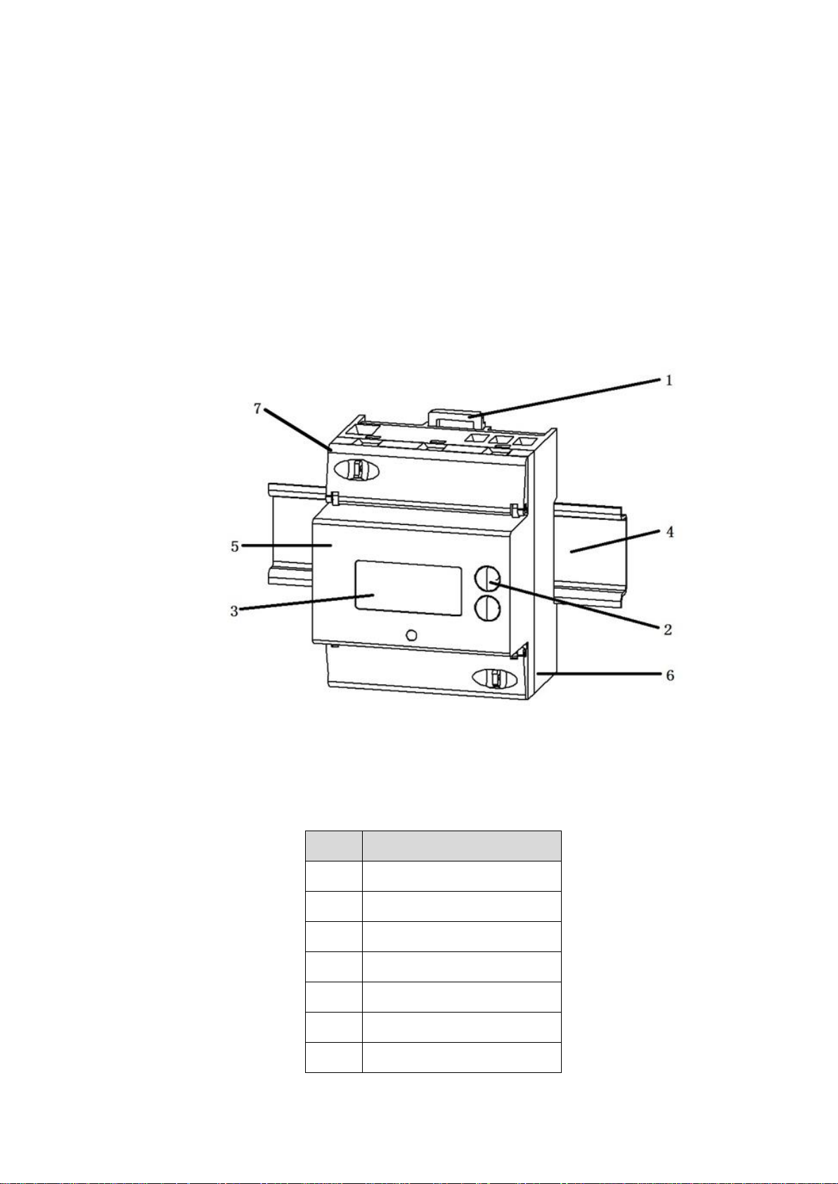
3Dimension, Assembling and Installation EV3 012-100..........................................................10
3.1 Assembling and dimensions ...................................................................................................10
3.2 Installation...................................................................................................................................12
3.3 Protection Housing ...................................................................................................................13
3.4 EV3.................................................................................................................................................14
4LCD-Display ...............................................................................................................................15
5User Buttons..............................................................................................................................16
6Test LED .....................................................................................................................................16
7Components .............................................................................................................................. 17
7.1 Block diagram............................................................................................................................. 17
8Functionality .............................................................................................................................18
8.1 Measurement..............................................................................................................................18
8.1.1 Instantaneous parameter measurements..........................................................18
8.2 Display Modes.............................................................................................................................18
8.2.1 Status Diagram.........................................................................................................19
8.2.2 AUTO Mode and ALT Mode ................................................................................... 20
8.3 Fatal Error................................................................................................................................... 20
8.4 Backlight EV3 ............................................................................................................................. 20

4/21
1General Information
1.1 Responsibility
The owner or provider is responsible for the proper use of the device. The installation, put-
ting into operation and reinstallation of the meter is only allowed to be done by electrically
skilled persons, which got knowledge about the contents of this user manual.
1.2 Common safety instructions
For installation, setting into operation and installation of the device the local requirements
for safety requirements must be observed.
Danger
Inappropriate use of parts under high voltage may lead to grave injuries and ac-
cidents, which may be fatal even with 230V.
The conductors which are connected to the device must be disconnected to the
mains during assembling and installation. It must be used a prevention for be-
ing switched on accidentally.
The device is not allowed to be used out of specifications.
1.3 Service and warranty instructions
Damaged devices can’t be repaired by you. The warranty and liability will be terminated with
opening the device. The same applies to damages caused by external influences.
For the device no servicing is required.
1.4 Disposal (product end of life information)
This meter was designed and built by ABB to provide many years of service and is backed by
our commitment to provide high quality support. When it eventually reaches the end of its
serviceable life, it should be disposed in accordance with local or national legislation.

5 /21
1.5 Environment
This meter is designed for indoor or in a cabinet environment only (avoiding extreme weather
conditions) in accordance with EN50470-1 and EN50470-3, with the terminal cover fitted.
1.6 Service and Warranty
This meter product is warranted against defects in material and workmanship for a period of
one year from date of shipment. During the warranty period ABB will at its option, either re-
pair or replace products which prove to be defective. For warranty service or repair, this prod-
uct must be returned to a service facility designated by ABB. ABB does not warrant that the
operation of the meter or firmware will be uninterrupted or error free.
Damaged devices can’t be repaired by you. The warranty and liability will be terminated with
opening the device. The same applies to damages caused by external influences.
For the device no servicing is required.
1.7 Cyber Security Disclaimer
EV meter is designed to be connected and to communicate information and data via a net-
work interface, which should be connected to a secure network. It is your sole responsibility
to provide and continuously ensure a secure connection between the product and your net-
work or any other network (as the case may be) and to establish and maintain appropriate
measures (such as but not limited to the installation of firewalls, application of authentica-
tion measures, encryption of data, installation of antivirus programs, etc.) to protect the me-
ter, the network, its system and interfaces against any kind of security breaches, unauthor-
ized access, interference, intrusion, leakage and/or theft of data or information. ABB S.p.A.
and its affiliates are not liable for damages and/or losses related to such security breaches,
unauthorized access, interference, intrusion, leakage and/or theft of data or information.
Although ABB S.p.A. provides functionality testing on the products and updates that we re-
lease, you should institute your own testing program for any product updates or other major
system updates (to include but not limited to code changes, configuration file changes, third
party software updates or patches, hardware change out, etc.) to ensure that the security
measures that you have implemented have not been compromised and system functionality
in your environment is as expected.

6 /21
1.8 Symbols
Danger through Electric Voltages
The symbol indicates warnings, which may lead to personal inju-
ries or death if it is ignored. Take all necessary precautions to
avoid danger!
Warning
The symbol indicates warnings to a possible dangerous situation
which may lead to personal injuries or damage to properties.
Avoid dangerous situations!
Attention!
“Attention” indicates warnings, which may lead to damage of
properties if not observed.
Notice
“Notice” indicates important information in the manual.

7/21
2Technical data
2.1 Abbreviations
+A Import active energy (to customer)
-A Export active energy (from customer)
EN European Standard
Imp/kWh Quantity of pulses each kWh
LCD Liquid Crystal Display
LED Light Emitting Diode
OBIS Object Identification System
+P Import active power
-P Export active power
2.2 Technical specifications
Type
Three phase direct
Voltage
Nominal voltage Un
3x230/400 Vac
Voltage range
0.8 –1.15Un
Frequency
Nominal frequency fn
50 Hz
Frequency range
0.98 –1.02 fn
Current
Reference current Iref = Ib = 10 Itr
5 A
Maximum current Imax
65A
Minimum current Imin
0.25 A
Starting current Ist
0.004 Ib
Accuracy
Cl. B
Class B in compliance with EN 50470-3

8/21
Measuring Active Energy
Two Energy Directions
+A/-A
Meter constant
LED-Output
1000 Imp/kWh
Display
LCD
7 digit
Life cycle
> 12 years
RS485- Data Interface
Connector
3P meter: Three screws type
Parameter
9600/19200/38400 bps, 8E1
Communication protocol
Modbus RTU
Power Consumption
Voltage circuit
< 0.7 W / 5.5 VA at Un
Current circuit
< 0.015 VA at Ib
Temperature Range
Typical Operation
-30°C to +70°C
Storage
-40°C to +85°C
EMC Properties
Isolation
4 kV AC, 50 Hz, 1min
High Voltage
7kV, Impulse 0.1/2000 µs
Housing
Dimension
DIN-Rail 90x70x62 mm
Material
fiber-glass reinforced Polycarbonate
(flame resistant EN 62053-21)
Class of protection
II
Degree of protection
IP21 (IP 51 in protective enclosure)
Weight
Weight
appr. 0,26 kg
Environment
Mechanical environment
Class M1 as per 2014/32/EU Directive.
Electromagnetic environment
Class E2 as per 2014/32/EU Directive.
Tab. 1: Technical Properties

9 /21
2.2.1 Technical Standards
EN 50470-1: Electricity metering equipment (AC) -Part 1: General requirements, test and
test conditions Metering equipment (class indexes A, B, and C);
EN 50470-3: Electricity metering equipment (AC) -Part 3: Particular requirement Static me-
ters for active energy (class indexes A, B, and C);
EN 50022: Low voltage switchgear and control gear for industrial use; mounting rails,
top hat rails, 35 mm wide, for snap-on mounting of equipment
IEC 62053-21: Static meters for active energy (classes 1 and 2)
IEC 62052-11: Electricity metering equipment (AC)-General requirements, tests and test con-
ditions –part 11: metering equipment

10/21
3Dimension, Assembling and Installation
EV3 012-100
3.1 Assembling and dimensions
The meter constructed for assembling on DIN-rail TH 35-7.5 according to IEC 60715.
1 Housing EV3
Nr
Element
1
Meter Hook
2
User Buttons
3
LCD
4
DIN Rail
5
Meter cover
6
Meter case
7
Terminal block with cover

11/21
2 Housing EV3 dimension (mm)
3 Terminal block (mm)

12/21
3.2 Installation
4 Connection diagram EV3
The connection diagram printed on the housing needs to be considered connecting the me-
ter to the mains power.
Terminal
Terminal
Nr
Terminal-
[mm]
Terminal screw
Torque M [Nm]
Current In L1
1
6,3 x 5,6
(L x W)
M4 Pozidrive PZ2
1,2 Nm< M <1,5Nm
Current Out L1
3
Current In L2
4
Current Out L2
6
Current In L3
7
Current Out L3
9
Voltage N
10
RS485 Interface GND
21
6,3 x 5,6
(L x W)
M3 Pozidrive PZ2
0,5 Nm <M <0,7Nm
RS485 Interface B
22
RS485 Interface A
23

13/21
Warning
The requirements of the net provider need to be full filled.
Selective hedges have to be used according requirements of the net providers.
Attention!
Damage of the terminals due to high torque
The specified maximum torques must not be exceeded!
Ensure that the connected lines are fixed with the needed torque compliant to
EN 60999 for a safe connection. The needed torque depends on the type of
used lines and the maximum current.
3.3 Protection Housing
As indicated in image 11 the cover of the terminal blocks can be sealed after installation.
The assembled meter base and meter cover will be protected against unauthorized opening
with a manufacturer label (format 8x20 mm, corner radius 0.5 mm) on both sides of the
housing.
5 Sealing
Important
Warranty and accuracy are void if sealing labels are removed.

14/21
3.4 EV3
6 EV3 Nameplate
Nr
Element
Function
1
Terminal block with cover
sealable terminal cover
2
Meter number
with barcode 128
3
User buttons
Information describe in chapter 7
4
LCD
7 digits with additional symbols
5
Meter type
6
LED
test LED 1000 Imp/kWh
7
Technical nominal data
8
3 phase 4 Wire
Protection class
Two energy directions
Import (+A) and Export (-A) energy measurement
Security symbol
9
Firmware version

15/21
10
Number approval document
year of certification
CE sign, year of certification, named body for MID approval
11
Manufacture year
4LCD-Display
The LCD has the following format:
- LCD size: 37.5 mm × 17 mm
- Digit size: 3.38 mm × 1,53 mm
7 EV3 LCD
7: LCD-Display
Nr
Element
Function
1
Unit
unit of the displayed value (kWh, W, V, A)
2
Values
according defined display list
3
Indication of phase voltages
Symbol off: loss of phase
Symbol is flashing: reverse sequence, reverse polarity,
Lx >1.15Un or Lx<0.8Un.
4
Indication current direction
Export

16/21
Import
5
OBIS Code
Identifier of the displayed value
5User Buttons
8 EV3 User buttons
Nr
Element
Function
1
Button „Up“
-Switch backlight of the LCD ON
-Scrolling the display items
-Enter display ALT Mode
2
Button „Down“
-Switch backlight of the LCD ON
-Scrolling the display items
-Enter display ALT Mode
The detailed functions of the buttons to switch into the different display modes is explained
under the chapter 8.4 Display Modes.
6Test LED
The meter has one pulse LED for active energy with 1000 Imp/kWh.
The ON-time of a pulse is 40 ms.

17/21
7Components
7.1 Block diagram
9 Block diagram
Current measuring: Manganin shunt
Voltage measuring: Resistor divider
A/D: Analog to digital converter for the sampled voltage and
current
MCU: Micro Controller Unit
Communication interface: RS485-Interface
Data storage EV3: nonvolatile storage for energy register +A/-A and meter pa-
rameter in EEPROM.
Display EV3: LCD with 7 digits
LED Pulse output: Active energy +A and -A, 1000 Imp/kWh

18/21
8Functionality
8.1 Measurement
The meter measures three phase active energy with accuracy class B.
The meter provides registers for total import, total export and net energy.
Additionally, each phase L1, L2 and L3 for import and export energy are measured.
The measurement of the energy is based on the measured power according the following cal-
culations:
Ptotal = PL1 + PL2 + PL3
Ptotal> 0: counting energy for +A
Ptotal< 0: counting energy for -A
8.1.1 Instantaneous parameter measurements
The instantaneous values can be read out via RS485 interface.
● Voltage and current
● Power factor
● Active power
● Frequency
8.2 Display Modes
The meter support three different display modes:
-AUTO Mode
-ALT Mode

19/21
8.2.1 Status Diagram
10 Status diagram display mode
After power on the meter shows for 2s self-check status and goes on to the AUTO-Mode.
With the user buttons it can be changed between the different modes.

20/21
8.2.2 AUTO Mode and ALT Mode
In the AUTO Mode and ALT Mode all values which may be used for energy are displayed. This
part of the display list can’t be changed by the user with any interface of the meter.
The display lists can be expanded with additional values by the user via the RS485 interface
and a parameter setting program. Each list can have 32 entries.
The different values are displayed with the following formats and units:
Type of value
Format
unit
Energy
x.xx
kWh
Power
x.xx
W
Voltage
x.x
V
Current
x.xx
A
Power Factor
x.xxx
---
Frequency
x.xx
---
Firmware Version
---
Checksum
---
Tab. 7: Format/Unit Displayed Values
In the AUTO Mode the next value of the defined list is displayed automatically with a settable
time period.
In the ALT Mode the next value is displayed after a user button was pressed.
8.3 Fatal Error
The meter has implemented a self-monitoring system. If the meter recognizes improper op-
eration so that billing relevant values may not be used anymore it displays “--FF--” This status
will be indicated with current display items flashing (1Hz).
8.4 Backlight EV3
Backlight will be on after pressing button, it’s useful to read meter through LCD when it in
dark environment. Light on time is configurable from 5s to 60 seconds.
The back light will be turned off unconditionally if the voltage is less than 0.8Un.
Table of contents
Other ABB Measuring Instrument manuals

ABB
ABB CoreSense M10 User manual

ABB
ABB VA Master FAM540 Training manual

ABB
ABB Navigator 600 Phosphate User manual

ABB
ABB i-bus EIB Delta-Meter User manual

ABB
ABB ProcessMaster FEP630 series User manual

ABB
ABB GAA330-M User manual

ABB
ABB ICOS GLA151 Series User manual

ABB
ABB MAG-X 3000 Series User manual

ABB
ABB C13 User manual

ABB
ABB aquamaster User manual

ABB
ABB CoriolisMaster FCM2000 User manual

ABB
ABB AO2000 Series User manual

ABB
ABB Endura AZ20 series User manual

ABB
ABB SCC-E User manual

ABB
ABB aquamaster User manual

ABB
ABB WaterMaster User manual

ABB
ABB CoriolisMaster FCB100 User manual

ABB
ABB ProcessMaster FEP611 User manual

ABB
ABB Comem eOLI22 User manual

ABB
ABB RELION 650 SERIES User manual