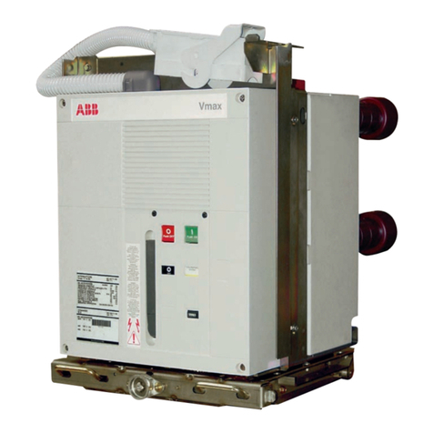
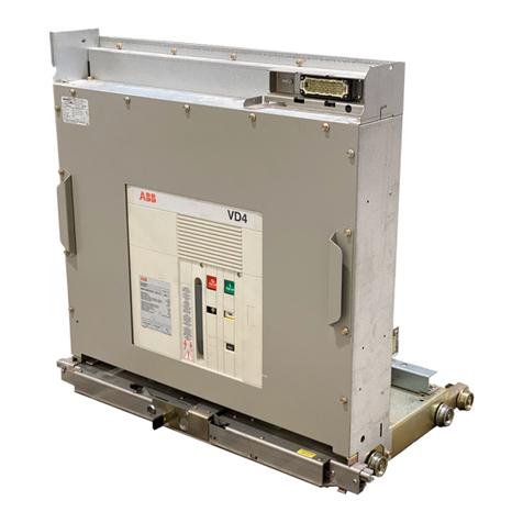
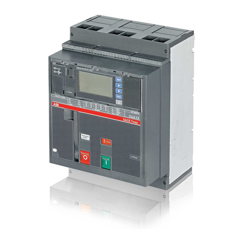
ABB VD4 Series User manual


Onlyinstallswitchgearand/orswitchboardsinenclosedroomssuitablefor
electricalequipment.
Ensurethatinstallation,operationandmaintenancearecarried outby
specialist electriciansonly.
Observetherelevantinformation intheinstructionmanualforall actions
involving switchgearandswitchboards.
Danger!
Payspecialattentiontothehazardnotesintheinstructionmanualmarkedwith
thiswarningsymbol.
Makesure thatunderoperationconditionofthe switchgear orswitchboard
thespecifieddataarenotexceeded.
Keeptheinstructionmanualaccessibletoallpersonsconcernedwith
installation, operationand maintenance.
Theuser'spersonnelaretoact responsiblyinall mattersaffectingsafetyat
workandthe correcthandlingoftheswitchgear.
If youhaveanyfurtherquestionsonthisinstruction manual,themembersofour
fieldorganizationwill bepleasedtoprovidetherequiredinformation.
That'swhyourinstruction manualbeginswiththeserecommendations:
Your safety first always!
WARNING
Always observethe instruction manualandfollowthe rules
ofgood engineering practice!
Hazardousvoltage
can causeelectricalshock and burns.
Disconnectpower,thenearthand short-circuitbeforeproceeding
withanyworkon thisequipment.
Complyinfullwiththe legallyrecognized standards,the connection
conditionsofthe localelectricalutilityandtheapplicablesafetyatwork
regulations.

1 Summary 5
1.1 General 5
1.2 Standards and specifications 5
1.2.1 Switchgearmanufacture 5
1.2.2 Installation and operation 5
1.3 Operating conditions 5
1.3.1 Normaloperating conditions 5
1.3.2 Specialoperating conditions 5
2 Technicaldata 6
2.1Technicaldata 6
Circuit-breakersforfixed installation
and on withdrawablepart
2.2 Technicaldata 7
Releases and blocking magne
2.3 Technicaldata 7
Motor-operated mechanisms
2.4 Permissiblenumber of vacuuminterrupter 8
switching operations inrelation tobreaking
current
2.5 Dimensions 9
3 Structureand function 13
3.1 Structureofthe breakerpoles 13
3.2 Structureofthe breakeroperating mechanism 13
3.2.1 Releases,blockingmagnetandauxiliaryswitches13
3.3 Function 14
3.3.1 Charging ofthe spring energy store 14
3.3.2 Closing procedure 14
3.3.3 Opening procedure 14
3.3.4 Autoreclosing sequence 14
3.3.5 Quenching principleofthe vacuuminterrupter 14
4 Dispatch and storage 18
4.1 Condition on delivery 18
4.2 Packaging 18
4.3 Transport 18
4.4 Delivery 19
4.5 Intermediatestorage 19
5Installation 20
6Commissioning/Operation 21
6.1 Noteon safetyatwork 21
6.2 Preparatoryactivities 21
6.3 Operation ofthecircuit-breaker 21
6.3.1 Chargingthe spring energy storage mechanism
Circuit-breakerswithcharging motors 21
6.3.2 Closing and opening 21
6.3.3 Operating sequence 22
7Maintenance 25
7.1 General 25
7.2 Inspection and functionaltesting 25
7.2.1 Switching devices ingeneral 25
7.2.2 Stored-energy spring mechanism 25
7.2.3 Checking auxiliaryswitch settings on
withdrawablepart 25
7.2.4 Testing ofinterlock conditions 26
7.2.5 Breaker pole 26
7.3 Servicing 26
7.3.1 Switching devices ingeneral 26
7.3.2 Stored-energy spring mechanism 27
7.3.3 Breaker pole 27
7.4 Repair 27
7.5 Sparepartsand auxiliarymaterials 28
8Application ofthe X-ray regulations 31
4 Contents| VD4Vacuum Circuit-breaker
Contents

1.1General
Thevacuumcircuit-breakersof type VD4 on with-drawable
partsfor36kVor40.5kVratedvoltageareintendedfor
indoorinstallationinair-insulatedswitchgearsystems.Their
switching capacityissufficienttohandleany conditions arising
fromswitchingofequipmentandsystemcomponentsunder
normaloperatingandfaultconditions, particularlyshort-
circuits,withintheparametersoftheirtechnicaldata.
Vacuumcircuit-breakershave particular adswitching frequency
intheworking currentrange and/or whereacertainnumber
of short-circuit breaking operationsareexpected. TypeVD4
vacuumcircuit-breakersaresuitablefor auto-reclosing,and
have exceptionallyhigh operating reliabilityand long life.
Thevacuumcircuit-breakersdesignedincolumnform,are
suppliedas withdrawablemodules. Theirbasicstructureis
shown infigures 3/1,3/2,3/7and 3/8.
1.2Standards and specifications
1.2.1Switchgearmanufacture
The switchgear complies withthe following specifications in
accordancewithGB,IEC andthe relevantDINVDE
publications respectively.
GB/T11022,IEC62271-1and DINVDE 0670part 1000,
"Commonspecificationsforhighvoltageswitchgearand
controlgearstandards".
GB1984 and IEC62271-100,"High-voltagealternating-
currentcircuit-breakers".
1.2.2Installation and operation
Therelevantspecificationsaretobetaken intoaccountduring
installation and operation,particularly:
IEC 61936-1, Electricaldevices withrated voltage above
AC 1kV
DINVDE 0101,Powerinstallations exceeding AC 1kV
DINVDE 0105,operation ofelectricalinstallations
DINVDE 0141,earthing systemsforspecialpower
installationswithrated voltages over1kV
Accident prevention regulationsissued by theappropriate
professionalbodies orcomparableorganisations.
InGermany,these comprisethe following safetyregulations:
Healthand SafetyatWorkStandardVBG1
Healthand SafetyatWorkStandardVBG4
Safetyguidelinesforauxiliaryand operating materials
Orderrelated detailsprovided by ABBXiamen Switchgear
Co.,Ltd.
1.3Operatingconditions
1.3.1Normaloperating conditions
Design toGB/T11022,"Common specification forhigh-voltage
switchgear and controlgearstandards", IEC62217-1,VDE0670
part1000,withthe following limitvalues:
Ambienttemperature:
Maximum +40℃
Highestmean value measured in24 hours +35℃
Minimum(according to"minus 5indoorclass") -15℃
Humidity
Highestmean valueofrelativehumiditymeasuredover
24 hours 95%
Highestmean valueofvapourpressuremeasuredover
24 hours 2.2kPa
Highestmean valueofrelativehumiditymeasuredover
1month 90%
Highestmean valueofvapourpressuremeasured over
1month 1.8kPa
Maximumsitealtitude:
1000mabove sealevel
1.3.2Specialoperatingconditions
Specialoperatingconditionsaretobeagreed on by the
manufactureranduser. Themanufacturer must beconsulted
inadvanceabouteach specialoperating condition:
Sitealtitudeover1000 m:
Allow forthe reduction inthe dielectricstrengthof the
air.
Increased ambienttemperature:
Currentcarrying capacityisreduced.
Provide additionalventilationforheatdissipation.
Climate:
Avoidthe riskofcorrosion orotherdamage inareas:
○withhigh humidityand/or
○withmajorrapidtemperaturefluctuations.
Implementpreventive measures (e.g.electricheaters)
toprecludecondensation phenomena.
VD4Vacuum Circuit-breaker |Summary 5
1Summary

Breaker-
type
VD4...
3612-25
3616-25
3620-25
3625-25
3612-31
3616-31
3620-31
3625-31
4012-25
4016-25
4020-25
4025-25
4012-31
4016-31
4020-31
4025-31
Rated
voltage
kV
36
36
36
36
36
36
36
36
40.5
40.5
40.5
40.5
40.5
40.5
40.5
40.5
Rated
current
A
1250
1600
2000
2500
1250
1600
2000
2500
1250
1600
2000
2500
1250
1600
2000
2500
Rated
short-circuit
breaking
current,
symm.1)
kA
25
31.5
25
31.5
Rated
short-circuit
breaking
current,
asymmetr.1)
kA
27.3
34.3
27.3
34.3
Rated
short-circuit
mreaking
current,
(peak.)1)
kA
63
80
63
80
Rated
short-circuit
duration
s
4
4
4
4
Pole
Centres
FixedWith-
draw-
able
mm
360 280
360 280
360 280
360 280
Weight
FixedWith-
draw-
able
approx.kg
320 290
320 290
355 340
355 340
320 290
320 290
355 340
355 340
290 290
290 290
340 340
340 340
290 290
290 290
340 340
340 340
Guidelinevalues forfunctiontimes atthe rated supplyvoltage:
1) When the operatingvoltageislower than the ratedvoltage,the samevaluesapplyasfor ratedvoltage.Higher valueson request.
2) Ifthe activatingrelaycontactcannotitselfinterruptthe releasecoil current
6 Technicaldata| VD4Vacuum Circuit-breaker
2Technicaldata
Ratedvoltage
Ratedfrequency
Ratedlightningimpulsewithstandvoltage
Ratedpowerfrequencywithstandvoltage(1min)
Rateofriseoftransientrecoveryvoltage
Peakoftransientrecoveryvoltage
Ratedoperatingsequence
Ratedoperatingsequence withautoreclosing
kV
Hz
kV
kV
kV/ s
kV
36
50/60
170
70
0.57
62
40.5
50/60
185
95
0.69
70
O-3min-CO-3min-CO
O-0.3s-CO-3min-CO
Closingtime
Openingtime
Arcingtime(at50Hz)
Totalbreaktime
Minimumcommandtimeon closing
Minimumcommandtimeon opening
approx.
approx.
≤
≤
55~67 ms
33~45 ms
15 ms
60 ms
20 ms(120 ms 2) )
20 ms(80ms 2) )
2.1Technicaldata
circuit-breakersforfixed installation andon withdrawablepart

VD4VacuumCircuit-breaker |Technicaldata 7
Equipment
ShuntreleaseOFF
ShuntreleaseON
Blockingmagnet
Undervoltagerelease
undelayed
delayed
Indirectovercurrentrelease
withintermediatecurrenttransformer
two-phase
three-phase
Y23),Y9 3)
Y24),Y9 4)
Y33)
Y34)
Y13) 4)
Y4
Y7
Powerconsumption1)
AC
VA
250
310
250
310
10
11
10
3.5 2) /15
2.0 2) /15
DC
W
250
310
250
310
10
10
-
-
-
1) Approximatevalues
2) Withshort-circuitedintermediatecurrent transformer
3) AuxiliaryvoltagesAC: 110 and 220 V,DC:24, 48,60,110and220V.
4) AuxiliaryvoltagesAC: 240 V, DC: 125 and 240 V.
2.3Technicaldata
Motor-operated mechanisms
Auxiliary

voltage
V
AC
110
220
240
DC
24
30
48
60
110
125
220
240
consumption1)
Power
VA/W
200
200
200
180
180
180
180
190
190
190
190
Chargingtime
(maximum)2)
s
15
15
15
15
15
15
15
15
15
15
15
1) Approximatevalues
2) Atthe rated auxiliaryvoltage
2.2Technicaldata
Releasesand blocking magnet

a) Circuit-breakertypeVD4, 36kVand40.5kV
Rated short-circuit breakingcurrent 25kA
b) Circuit-breakertypeVD4, 36kVand40.5kV
Ratedshort-circuit breaking current 31.5kA
Breakingcurrent I (kA)
aBreakingcurrentI (kA)
a
10
88
6
4
3
2
10 5
8
6
4
3
2
4
10
88
6
4
3
2
3
10
8
6
4
3
2
2
10
8
6
5
0.05 0.1 0.2 0.3 0.4 0.6 0.8 1 2 3 4 6 8 10 20 30 40 60
10
88
6
4
3
2
10 5
8
6
4
3
2
4
10
88
6
4
3
2
3
10
8
6
4
3
2
2
10
8
6
5
0.05 0.1 0.2 0.30.40.60.8 1 2 3 4 6 810 20 3040 60
Rated
current
1250A
1600A
2000A
2500A
2.4Permissiblenumberofvacuuminterrupterswitching
operations inrelationtobreaking current
See figure2/1.
Rated
current
1250A
1600A
2000A
2500A
8 Technicaldata| VD4Vacuum Circuit-breaker
Figure 2/1 Permissible numberof vacuum interrupteroperating cyclesn asa function of the breaking current Ia
Figure 2/1

Note:
Transport bracketTK(147)andtransport
profileTP(148)only fittedfor handling.
Removeand store priortocommissioning.
TK=Transportbracket147
TP=Transport profile148
K =Entranceforcontrolcables
50.2=Frontpartitionplate
Fig. 2/2 Dimension of withdrable VD4 40.5kV|Fig. 2/3 Dimensionof fixed VD4 40.5kV
Fig. 2/2
Fig. 2/3
1105
1065
920
868
61139.5
124
40
35
36
14
36
435
445
555
535
685
75
60
390
260
62
A
360 360
4-11
40
DETAILA
Vacuumcircuit-breakerforfixed
installation:
...1250A =1×80×10mm
>1250...2000A =2×80×10mm
2500A =3×80×10mm
VD4Vacuum Circuit-breaker |Technicaldata 9
2.5Dimensions
See figure2/2,2/3.
a
O74
O113
b
O35
O79
Ratedcurrent
1250/1600A
2000/2500A

Charging motor
Standard
arrangement
Type22
1)Onlywhen Y1isnot fitted
2)Externaloperation
Specialarrangementfor-S5
Type19 Type20 Type21 Type23 Type24
S1Auxiliaryswitch onoperatingmechanism
S2Auxiliaryswitch onblockingmagnet
S3Auxiliaryswitch onthebreakershaft
S4Auxiliaryswitch onthebreakershaft
S5Auxiliaryswitch onthebreakershaft
S7Auxiliaryswitch forfaultannunciation
(fleetingcontact,time≥30ms)
Y1Blockingmagnet
Y2ShuntreleaseOFF
Y3ShuntreleaseON
Y4Undervoltagerelease
Y7Indirectovercurrentrelease
Y9SecondshuntreleaseOFF
V1Seriesrectifierfor Y1
V2Seriesrectifierfor Y2
V3Seriesrectifierfor Y3and KO
V4Seriesrectifierfor Y4
V7Seriesrectifierfor Y7
V9Seriesrectifierfor Y9
MOChargingmotorforstored-energyspring
KOAnti-pumpingrelay
ROSeriesresistor
Fig.2/4Circuitdiagramformotor-charged operationmechanism
Fig. 2/4
10 Technicaldata| VD4VacuumCircuit-breaker
Note:1)For DC 24V, 30V, 48V, 60V, 110V, 125V,220V, 240V; AC 110V, 220V,240V
2)Springin the diagramisdischarged.Standardconfigurations andoptionsavailableforVD4are containedinthe diagram. Alsosee relativecataloguesandorder
forms for allpossibleconfiguration.
3)Releases andblockingmagnetsarefundamentallywired withrectifiers(e.g. magnet holder 45 withintegratedrectifiersV1, V2,V3andV9). Rectifiersfunction as
free-wheelingdiodeswithDCsupply.
Tag. Available auxiliary circuitcomponents

1) Motorcharged,fixedversion: Y2,Y3,KO,S1,S3, S4, MO
2) Motorcharged,withdrwableversion:Y1,Y2, Y3,KO, S1,S2,S3,S4, S8,S9,MO
Anyrequirement exceedmentionedabove, shouldbedeclaredinthe contract.

Fig.2/5CircuitdiagramforwithdrawableVD4
Fig. 2/5
VD4Vacuum Circuit-breaker |Technicaldata 11

Fig.2/6Circuitdiagramforfixed VD4
Fig. 2/6
12 Technicaldata| VD4Vacuum Circuit-breaker

3.1Structureofthebreakerpoles
(Figures 3/1,3/2,3/6,3/7and 3/8)
The 36 kV and 40.5kVcircuit-breakersoftype VD4 are
designedaswithdrawableunits.Thepoles,which are
constructedincolumnform,aremountedon atorsionally
rigidenclosuresubstructurewithrollers.Thelivepartsofthe
breakerpoles arelocated inthe insulating materialpole
tubesandprotectedfromimpactsandotherexternal
influences.
Withthe breakerclosed,thecurrentpathleads fromthe
uppercontactarm57.1and achamber holderfixed inthe
poletubetothefixed contact58.2inthevacuuminterrupter
58,then viathemoving contact58.3and rollercontact
tothelowercontactarm57.2.Theswitching motionis
effected bymeans ofthe insulated couplingrod withinternal
contactforce springs.
3.2Structureofthe breakeroperatingmechanism
(Figures 3/3, 3/4,3/7,6/1to6/5,7/5to7/8)
The operating mechanismlocated inthe housing substructure
isofthe stored-energy spring typeand actsonthe three
breakerpoles. Thenecessaryoperatingenergy isstored
ready foractivation by charging the spring energystorage
mechanism.
The stored-energy spring mechanismessentiallyconsists
ofdrum55.33 containing the spiralspring,the charging
system,thelatchingandoperatingmechanismandthe
linkages which transmitthe force tothe breakerpoles.In
addition,therearesupplementarycomponentssuch asthe
charging motor,releases,auxiliaryswitches and the controls
and instruments.
Theoperatingmechanismisfundamentallysuitablefor
autoreclosingand,due totheshort chargingtimes, alsofor
multi-shotautoreclosing.
The operating mechanismisnormallyfitted withacharging
motor.Thereisalso afacilityfor charging the stored energy
spring manually.
Thereisone rating plate55.7withthemaindataofthe switch
equipmentonfrontcoverplateleft hand side50.7,and
anotheronbreakermechanismhousing.
Thebasicversionofthestored-energy springmechnism
isfittedwiththefollowing auxiliaryequipment:
Shuntrelease OFFY2
Shuntrelease ONY3
Blocking magnetY1withauxiliaryswitch S2
Five-poleauxiliaryswitchesS3 and S4
ON-OFF operatingshaft54
Mechanicalswitch position indicator55.4
Chargingconditionindicator55.8forthestored energy
spring
Mechanicaloperating cyclecounter 55.5.
Motorcharging mechanism
Five-poleauxiliaryswitch S1 toswitch the charging motor
Anti-pumping relay K0.
The following additionalequipmentcan be installed:
Blocking magnetY0on the withdrawablepart
Second shuntrelease OFFY9
Indirectovercurrentrelease Y7
Auxiliaryswitch S7 for electricalopening signalling
Undervoltage releaseY4
Five-poleauxiliaryswitch S5
3.2.1Releases,blocking magnetand auxiliaryswitches
(Figures 2/4to2/6,3/3,6/2,7/7and7/8)
Thereleases and theblockingmagnetaremountedat the
bottomofthe stored-energy springmechanism.
Theallocationoftheauxiliaryswitchescanbeseeninthe
wiring diagramoffigure2/4.
Thefive-poleauxiliaryswitchS1isoperated by the charging
condition indicator55.8.Itcontrolsthe chargingmotorM1,
serves as an electricalinterlockforshuntrelease ONY3when
the spring energy storage mechanismisnotsufficiently
charged,and also provides anelectricalswitching readiness
signal.
Operationof thefive-poleauxiliaryswitches S3, S4 and S5
isdependentontheswitchingpositionof thecircuit-breaker.
Auxiliaryswitch S3 interruptsthe circuitofthe optional
additionalshuntrelease OFF Y9 withthe circuit-breaker
inthe open position,and the circuitsofshuntrelease ONY3
andthe optionalblocking magnetY1withthe circuit-breaker
intheclosedposition.ThereisonefurtherNOCforother
purposes.
AuxiliaryswitchS4interruptsthe circuitofshuntrelease
OFFY2withthecircuit-breakerintheopenposition.One
furtherNOCandthree NCCsareavailableforannunciation,
controland interlock purposes.
Auxiliaryswitch S5 can be optionallydesigned withany
possiblecombination ofcontactsfromfive NOCstofive NCCs.
Itscontactsareavailableforany required control,annunciation
or interlock functions.The auxiliaryswitchisnormallyconfigured
as shown infigure7/3.
The singlepoleauxiliaryswitch S7(fleeting contacttime30
ms)servestoprovide afaultsignal("breakerreleased").
Withremotecontrol,the auxiliaryswitch isnecessarilyoperated
via:
Shuntrelease OFFY2 or
VD4VacuumCircuit-breaker |Structureandfunction13
3Structureandfunction

ShuntreleaseOFF Y9 or
Undervoltage release Y4or
Indirectovercurrentrelease Y7.
Note:
1.Shuntreleases OFF (Y2)andON(Y3)areexclusively
providedforopeningandclosinginnormaloperation. For
safetybreakingoperations,thesecond shuntrelease OFF
(Y9) mustbeused,inmostcaseswithaseparatecontrol
voltage supply.
These three releases areofthe solenoidtype and suitable
foralarge numberofoperating cycles.
2. The undervoltage release (Y4)and/orindirectovercurrent
release(Y7)arepuresafetyand protectionreleasesand
mustnotbe used forswitchinginnormaloperation
3.3Function
3.3.1Charging ofthe spring energystore
(Figures 3/3,3/10,6/2,6/6,7/7and7/8)
To providethe necessarymotiveenergy,the spring energy
storagemechanismischargedviachain55.34fitted with
ratchet wheel55.35, either automaticallybyachargingmotor
orby hand inaverticalpumping action withcharging lever
128.Thecurrentchargingconditionisshownatcharging
condition indicator55.8
As aprecondition foran autoreclosingsequence,the
operating mechanismiseither(re-)charged afteraclosing
operationautomaticallyby thecharging motor,oritrequires
(re-)charging by handif the operating mechanismisofthe
manualtype.
3.3.2Closing procedure
(Figures 3/4,3/6,6/1,6/3and 7/7)
Theclosing process isinitiated manuallybythedouble
bitkey145and theON-OFFoperatingshaft 54,orelectrically
by activation ofshuntrelease Y3.Thereleasemechanism
then permitsdriveshaft 55.30toberotated bythe (previously)
chargedspiralspring.The movingcontact58.3invacuum
interrupter58 ismoveduntilthe contactstouch by camdisk
and furtherkinematiclinks.Inthefurthersequence ofmotion,
springarrangementistensionedandthe appropriateamount
ofcontactforcethusapplied.Theavailableovertravelis
higherthan themaximumvalue ofcontacterosion during
lifetimeofthe interrupter.During theclosing process,
openingsprings aresimultaneouslytensioned.
3.3.3Openingprocedure
(Figures 3/3,3/6,6/3and 7/7)
The openingprocedureisinitiatedmanuallybythedouble
bitkey145andtheON-OFF operatingshaft 54,orelectrically
by activationofoneofthereleasesY2,Y4,Y7orY9.
Release mechanismthen permitsdrive shaft55.30 tobe
turned furtherby the spring energy storage mechanism,
whichisstillsufficientlycharged.Theopeningspring,which
isthus released,movesthe contact58.3intothe open position
atadefinedspeed.
3.3.4Autoreclosing sequence
AnOFF-ONorOFF-ON-OFF autoreclosing sequenceis
activated and checked by theprotection system.Itisnecessary
forthe spiralspring inthe operating mechanismtobe in
the(re-)chargedcondition,withthecircuit-breakerinthe
closed position.The (re-)charging process iscarried out
automaticallyafterclosing ofthe breakeron breakers
withmotorcharging mechanisms,butmustbe carried out
manuallyon breakerswithout charging motors(orwhen the
chargingmotorhasbrokendown). Openingofthebreaker
isalsopossibleduring the (re-)charging process,butsub-
sequent closing ofthebreaker ishowever blockeduntilthe
charging process has been completed.
3.3.5Quenchingprincipleofthe vacuuminterrupter
Due tothe extremelylow staticinterrupterchamber pressure
of10-2 to10-6 pa,onlyarelativelysmallcontactgap isrequired
toachieve ahigh dielectricstrength.The arcisextinguished
onone ofthe firstnaturalcurrentzeros.
Due tothe smallcontactgap andthe high conductivityof
the metalvapourplasma,thearcdropvoltage, andadditionally,
duetothe shortarcingtime,the associated arcenergy,are
extremelylow,which has advantageous effectson the life
ofthe contactsandthus on that of the vacuuminterrupters.
14 Structureandfunction | VD4Vacuum Circuit-breaker

Figure3/1: Withdrawablepart withcircuit-breaker, type VD4,operator's side
Figure3/2: Withdrawablepart withcircuit-breaker, typeVD4,poleside
Figure3/3: Withdrawablepartwithcircuit-breaker,typeVD4,controlsforthecircuit-breaker
54 ON-OFF operatingshaft
54.1 Linkrod
55.4 Switchposition indicator
55.5 Operatingcyclecounter
55.6 Socketforcharginglever
55.7 Ratingplate
55.8 Chargingcondition indicator
50.2
57.1
57.8
57.2
50.1
50.8
50.1 Earthingcontact
50.2 Frontpartition plate
50.8 Wheel
57.1 Uppercontactarm
57.2 Lowercontactarm
57.8 Insulatingmaterial
poletube
54
54.1
55.8
55.6
55.5
55.4
55.7
VD4Vacuum Circuit-breaker |Structureandfunction 15
Figure3/1 Figure3/2
Figure3/3

58.1 Insulator
58.2 Fixedcontact
58.3 Movingcontact
58.4 Metalbellows
58.5 Screen
58.6 Guidecylinder
58.7 Lid
Figure3/4: Withdrawablepart withcircuit-breaker,type VD4, left and operator'ssideview
Figure3/5: Withdrawablepartwithcircuit-breaker,type VD4, (poleside, below)
Figure3/6: Partialsection of avacuum interrupter.
50.1
50.4
50.3
51
51.1
147
50
50.4
50.3
148
51.2
58.1
58.2
58.3
58.4
58.5
58.7
58.6
50 Frameofthewithdrawablepart
50.3 Actuatingpin
50.4 Guidecam
51 Interlockyoke
51.1 Catchpin
51.2 Slidinghandle
147 Transport bracket
148 Transport profile
50.1 Earthingcontact
50.3 Actuatingpin
50.4 Guidecam
16 Structureandfunction | VD4Vacuum Circuit-breaker
Figure3/4 Figure3/5
Figure3/6

Figure3/7:Vacuum circuit-breaker, type VD4, forfixedinstallation,operating side
Figure3/8:Vacuum circuit-breaker, type VD4, forfixedinstallation,terminalside
Figure3/9:Vacuum circuit-breaker, type VD4, forfixedinstallation,version withpartition, terminalside
Figure3/10: Indicatorsandcontrolson acircuit-breakerforfixedinstallation
57.2Lowerbreakerterminal
57.8Embedded pole
VD4Vacuum Circuit-breaker |Structureandfunction 17
50.7Front plate
54.2MechanicalONpushbutton
54.3MechanicalOFF pushbutton
55.4Mechanicalswitchposition indicator
55.5Mechanicaloperatingcyclecounter
55.6Socket(forcharginglever)
55.7Ratingplate
55.8Chargingcondition indicator
50.8Rollers
57.1Upperbreakerterminal
Figure3/7 Figure3/8
Figure3/9 Figure3/10

4.1Condition ondelivery
The factory-assembled circuit-breakerson withdrawable
partsarecheckedatthe worksforcompletenessofthe
equipmentinstalledand simultaneouslysubjectedtoa
routinetestinaccordancewithGB/T11022GB1984, IEC
60694,DINVDE 0607 IEC publication 62271-100,thus
verifying theircorrectstructureand function.
4.2Packaging
Thecircuit-breakersonwithdrawablepartsaremounted
individuallyon wooden palletsandsealedinfilmand/orpacked
incardboardfordelivery.
Packaging foroverseas shipment:
Dryingagentbags inserted inthe filmsealedpackaging.
4.3Transport
Loading ofthe package unitsmustonlybe carriedoutwitha
crane,
fork-lifttruckand/or
trolley jack.
Notes:
Avoidimpactduring handling.
Do notsubjecttootherdamaging mechanical
stresses.
Lifting gearmustnotbe attached tothe breaker
poles orpartsofthe operating mechanism.
When moving thewithdrawablepartonlyusethe
slidinghandles51.2(e.g.forrackingin/outthe
circuit-breakerunitinto/outoftheswitchgear
panelorforthe transportoftheunitinthe
switchgearroom). Do not bring anyforceonthefront
partition plate50.2ofthe withdrawablepart.
Onlyhandlethemodulesbycranewithboltedon
transportbrackets147,suitablelifting ropesand
crane harness.
Ensurethatthecircuit-breakerunitonthe
withdrawablepart,withitsrelative highsituated
centreofgravity,cannot tipover when moving it by
crane orfork-lift truck,orwhenhandlingit outside
the switchgearroom.
Onlyhandlebycranewhentheliftinglugsarefitted.
Alwaysbearinmind that thehighsituated centreof gravitymay
inducethe breakertotip over!
Onlyhandlebycranewhenthetransportbracket 147andcrane
harnessarefitted.Alwaysbearinmindthatthehighsituatedcentre
of gravitymayinducethebreakertotipover!
50.2 Frontpartitionplate(Donotstressthisplate)
147 Transport bracket(TK)
148 Transport profile(TP)
CrB Crossbar
CrB
18 Dispatchandstorage| VD4VacuumCircuit-breaker
4Dispatchandstorage
Figure4/1: VD4breakeron withdrawablepart |Figure4/2:VD4breakerforfixedinstallation
Figure4/1 Figure4/2

4.4Delivery
The duties ofthe consignee on receiptofthe switching
devices atsiteinclude the following:
Checking the deliveryforcompletenessand freedom
fromdamage (e.g.moistureand itsadverse effects).
Any shortquantities,defectsordamage intransit:
Mustbe preciselydocumented on theconsignmentnote.
Theshipper/carrieristobe notified immediatelyin
accordance withthe liabilityprovisions.
Note:
Always takephotographstodocumentanymajordamage.
4.5Intermediatestorage
Intermediatestorage ofthe circuit-breakerunitinthe switch
positionOFF andthe storedenergy spring mechanisms
discharged(IndicatorDISCHARGED:).
Conditions foroptimumintermediatestorage:
1.Devices withbasicpackaging orunpacked:
Adryand wellventilated storeroomwithclimatein
accordance withGB/T11022,IEC60694,DINVDE0670.
Roomtemperaturewhich does notfallbelow-15℃.
Do notremove ordamage the packaging.
Unpackaged devices:
Aretobe looselycovered withprotective sheeting.
Sufficientair circulation mustbe maintained.
Checkregularlyfor any condensation.
2.Devices withseaworthy orsimilarpackagingwithinternal
protective sheeting:
Storethetransportunits:
protectedfromthe weather,
dry,
safefromdamage.
Checkthepackagingfordamage.
Checkthedrying agent:
on arrivalofthe consignment,
subsequentlyatappropriateintervals.
VD4Vacuum Circuit-breaker |Dispatch andstorage 19

(Figures 3/4,4/1and 4/2)
Perfectoperation ofthecircuit-breakerdependsoncareful
andprofessionalhandling ofthewithdrawablepart.
Allocateeach unit tothe appropriateswitchgearpanelin
accordancewiththe switchgear plan andthe rated electrical
data.
Removethetransportprofile148and transportbrackets
147.
Insert the withdrawablepart intheswitchgearpanel
checking forunimpededmotionandfunction sequences,
including the closing ofprimarycontactswhen the service
position isreached.
Remove anydirt.
Whenthe switchgearsareoperatedinareas withhigh
humidityand/ormajorrapidtemperaturefluctuations,there
isarisk ofdew depositswhich mustremainan exception
innormaloperating conditionsProvisionsshouldbetaken
according tosection 1.3.2(specialoperating conditions).
20 Installation | VD4Vacuum Circuit-breaker
5Installation
Other manuals for VD4 Series
11
Table of contents
Other ABB Other manuals
Popular Other manuals by other brands

Hobo
Hobo U12 manual

Robinson
Robinson R-66 Series Lithium-Ion installation instructions

Risco
Risco RWS42043300A Installation and programming instructions

EMIT
EMIT Mini Zero Volt Ionizer 2 Installation, operation and maintenance guide

SuperSteer
SuperSteer SS401 installation instructions

Alutech
Alutech ProPlus Series operating manual