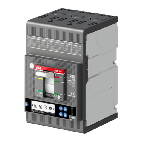
ABB SACE Emax E1.2 Quick start guide

DOC. N° 1SDH001330R0002 - ECN000058721 Rev. A
SACE Emax 2
Low voltage air circuit-breakers Emax E1.2-E2.2-E4.2-E6.2
Operating instructions for the design engineer

ABB | SACE Emax 2
2 | © 2017 ABB | 1SDH001330R0002 - ECN000058721 Rev. A |

© 2017 ABB SACE Emax 2 | I 1SDH001330R0002 - ECN000058721 Rev. A
Circuit-breakers E1.2-E2.2-E4.2-E6.2.......................................... 4
1 - Foreword ........................................................................4
2 - Contents .........................................................................4
3 - Standards .......................................................................4
Guide to the product choice ........................................................ 5
1 - List for Emax 2 selection.................................................5
Foreword .............................................................................. 5
Device................................................................................... 5
Standard............................................................................... 5
Mechanical characteristics ................................................... 5
Electrical characteristics....................................................... 6
Protection functions of the electronic trip units..................... 7
Electrical and mechanical accessories.................................. 8
Electronic accessories .......................................................... 8
2 - Selectivity between ABB SACE circuit-breakers .............9
Foreword .............................................................................. 9
Types of selectivity................................................................ 9
Further documents ............................................................... 9
Documents and Tools for the design engineer ......................... 10
1 - Foreword ......................................................................10
2 - Software list..................................................................10
e-Design ............................................................................. 10
DOC.................................................................................... 10
CAT ..................................................................................... 10
Curves ................................................................................ 10
DOCSolar............................................................................ 10
OTC .................................................................................... 10
Front CAD........................................................................... 11
Trip Unit simulator............................................................... 11
Ekip Connect ...................................................................... 11
Slide Rules.......................................................................... 11
Ekip View ............................................................................ 11
3 - Documentation list........................................................12
Brochure: introductory overview ......................................... 12
Brochure: History of air circuit-breakers ............................. 12
Brochure: retrofitting kit ...................................................... 12
Product notes for consultants............................................. 12
Product notes for switchgear engineers.............................. 12
Product notes the Ekip Link system.................................... 12
Product notes for Power Controller..................................... 12
Product notes for generator protections ............................. 12
Product notes: migration to Emax 2.................................... 12
White Paper for generator protections ................................ 13
White Paper for Ekip Power Controller................................ 13
White Paper for communication.......................................... 13
Product Notes for IEC 61850 .............................................. 13
Product notes for Network Analyzer ................................... 13
Catalogue ........................................................................... 13
Handbook ........................................................................... 13
Introduction to Ekip trip units.................................................... 14
1 - Presentation..................................................................14
Families and functionality ................................................... 14
Protections ......................................................................... 15
Measurements .................................................................... 16
Integrated functions: Self-diagnosis, Test and Power
Controller............................................................................ 16
Accessorizing modules ....................................................... 17
Ekip Dip protection trip unit....................................................... 18
1 - Operator interface.........................................................18
Introduction ........................................................................ 18
Components of the interface............................................... 18
LEDs................................................................................... 18
Protections: thresholds ....................................................... 19
Protections: times............................................................... 19
Settings .............................................................................. 19
iTest pushbutton ................................................................. 19
Test connector .................................................................... 19
2 - Protections ...................................................................20
L Protection ........................................................................ 20
S Protection........................................................................ 21
I Protection ......................................................................... 22
G Protection ....................................................................... 23
Neutral and frequency......................................................... 24
Additional protections......................................................... 25
Summary table of protections............................................. 26
3 - Measurements ..............................................................27
Introduction Measurements ................................................ 27
Instantaneous currents ....................................................... 27
Maximum and minimum currents........................................ 27
Trips.................................................................................... 27
Contact Wear...................................................................... 27
Number of operations ......................................................... 27
4 - Test...............................................................................28
Presentation........................................................................ 28
LED test.............................................................................. 28
Battery test ......................................................................... 28
Protection test .................................................................... 28
Opening test ....................................................................... 28
5 - List of alarms and signals ............................................. 29
LED view............................................................................. 29
Summary table of LED signals ............................................ 30
6 - Ekip Dip: additional functions .......................................32
Presentation........................................................................ 32
Maintenance ....................................................................... 32
Local Bus............................................................................ 32
Date and time ..................................................................... 32
Programmable States ......................................................... 33
Programmable Functions .................................................... 33
Circuit-breaker label and user Data..................................... 34
Info Page ............................................................................ 34
Date of installation .............................................................. 34
Load Profile Timers............................................................. 34
Energy Store Time .............................................................. 34
Led Alive............................................................................. 34
Open/Close Remote Direct Command ................................ 34
Modules network settings retention .................................... 34
Wink ................................................................................... 34
Glitch .................................................................................. 34
7 - Operating features ........................................................35
Primary operating currents.................................................. 35
Auxiliary power supply........................................................ 35
8 - Default parameters .......................................................36
Ekip Touch protection trip unit .................................................. 37
1 - Layout of the interface ..................................................37
Functions of the interface ................................................... 37
Components of the interface............................................... 37
Signallings .......................................................................... 38
Structure of the pages ........................................................ 38
Diagnosis bar...................................................................... 39
Main page........................................................................... 39
Start page........................................................................... 40
Navigation........................................................................... 40
2 - Alarm List Page.............................................................41
Description ......................................................................... 41
Components of the page .................................................... 41

II | © 2017 ABB SACE Emax 2 1SDH001330R0002 - ECN000058721 Rev. A
3 - Histograms Page ..........................................................42
Description ......................................................................... 42
Components of the page .................................................... 42
Possible operations ............................................................ 43
4 - Measuring instruments pages .......................................44
Description ......................................................................... 44
Components of the pages................................................... 44
Possible operations ............................................................ 44
5 - Measurements pages....................................................45
Description ......................................................................... 45
Components of the pages................................................... 45
Possible operations ............................................................ 45
6 - Menu.............................................................................46
Introduction ........................................................................ 46
Components of the page .................................................... 46
Components of the menus.................................................. 47
Protections Menu................................................................ 47
Advanced menus ................................................................ 48
Settings Menu..................................................................... 49
Test Menu ........................................................................... 50
About Menu ........................................................................ 51
Measurements Menu .......................................................... 51
Last Trip measurements...................................................... 52
Measurements history......................................................... 53
Waveforms.......................................................................... 54
Harmonics Measurement .................................................... 55
7 - Insertion of the password..............................................56
Function.............................................................................. 56
Description ......................................................................... 56
Components of the page .................................................... 57
8 - Setting the parameters..................................................58
Modifying a parameter........................................................ 58
Programming the trip unit ................................................... 58
Edit Parameters page by option.......................................... 59
Edit Parameters page by value ........................................... 59
Programming Page ............................................................. 60
9 - Touch protections .........................................................61
Presentation........................................................................ 61
L Protection ........................................................................ 62
S Protection........................................................................ 63
I Protection ......................................................................... 64
G Protection ....................................................................... 65
2I Protection ....................................................................... 66
Protection MCR .................................................................. 67
IU Protection....................................................................... 68
Hardware Trip ..................................................................... 68
Harmonic distortion ............................................................ 68
Current thresholds .............................................................. 69
T Protection ........................................................................ 70
Neutral................................................................................ 70
Iinst..................................................................................... 71
Additional functions ............................................................ 71
Summary table of basic protections.................................... 73
10 - Measuring Pro protections ..........................................75
Presentation........................................................................ 75
UV Protection ..................................................................... 76
OV Protection ..................................................................... 76
VU Protection ..................................................................... 77
UF Protection...................................................................... 77
OF Protection ..................................................................... 78
RP Protection ..................................................................... 78
Phase Sequence................................................................. 79
Cos φ.................................................................................. 79
Synchrocheck ..................................................................... 79
Summary table of Measuring Pro protections ..................... 80
11 - Hi-Touch protections...................................................81
Presentation........................................................................ 81
S2 Protection...................................................................... 82
D Protection........................................................................ 83
UV2 Protection.................................................................... 84
OV2 Protection ................................................................... 85
UF2 Protection.................................................................... 85
OF2 Protection.................................................................... 86
Set A-B............................................................................... 87
Hi- versions: additional functions........................................ 88
Summary table of Hi-Touch protections.............................. 89
Table of Additional functions of the protections .................. 89
12 - G Touch protections....................................................90
Presentation........................................................................ 90
S(V) Protection.................................................................... 91
RV Protection...................................................................... 92
RQ Protection ..................................................................... 92
OQ Protection..................................................................... 93
OP Protection ..................................................................... 94
UP Protection ..................................................................... 94
Summary table for G Touch protections.............................. 95
Table of Additional functions of the protections .................. 95
13 - G Hi-Touch protections ...............................................96
Presentation........................................................................ 96
ROCOF Protection .............................................................. 97
S(V) Protection.................................................................... 98
RQ2 Protection ................................................................... 99
Summary table of G Hi-Touch protections .........................100
14 - External toroid protections........................................101
Presentation.......................................................................101
Gext Protection..................................................................101
RC Protection ....................................................................103
Summary table of external toroid protections ....................104
Table of additional function of the Gext protection.............104
15 - Touch measurements ................................................ 105
Presentation.......................................................................105
Instantaneous currents ......................................................105
Tripping..............................................................................105
Events................................................................................106
Maximum and minimum currents.......................................107
Peak factor ........................................................................107
Contact Wear.....................................................................108
Datalogger .........................................................................108
Operation counters ............................................................109
Summary table of basic measurements .............................109
16 - Ekip Measuring Measurements .................................110
Presentation.......................................................................110
Instantaneous voltages ......................................................110
Instantaneous power .........................................................111
Tripping..............................................................................111
Maximum and Minimum voltage ........................................112
Maximum and minimum power ..........................................112
Power factor ......................................................................113
Energy counters.................................................................113
Instantaneous frequency....................................................113
Synchrocheck ....................................................................113
Summary table of Ekip Measuring measurements .............113
17 - Hi-Touch measurements ........................................... 114
Presentation.......................................................................114
Waveforms.........................................................................114
Harmonics .........................................................................114
Network Analyzer...............................................................114
18 - Test........................................................................... 118
Path ...................................................................................118
Presentation.......................................................................118
Autotest .............................................................................118
Trip Test .............................................................................118
© 2017 ABB SACE Emax 2 | III 1SDH001330R0002 - ECN000058721 Rev. A
Test CB..............................................................................118
Zone Selectivity .................................................................119
Ekip Signalling ...................................................................119
Rc Test...............................................................................119
19 - Self-diagnosis ...........................................................120
Alarms and signals.............................................................120
Self-diagnosis....................................................................120
Protections and Measurements .........................................121
Programming errors ...........................................................122
20 - Operating features .................................................... 123
Electrical characteristics....................................................123
21 - Additional Ekip Touch functions ................................124
Functional characteristics ..................................................124
Line frequency ...................................................................124
Local/Remote ....................................................................124
Local Bus...........................................................................124
Harmonics .........................................................................124
Power Controller................................................................124
Programmable functions....................................................125
System ..............................................................................125
Maintenance ......................................................................125
Additional options via remote / front control ......................126
Programmable States ........................................................126
Filters.................................................................................126
Circuit-breaker label and user Data....................................126
Info Page ...........................................................................126
Date of installation .............................................................127
Load Profile Timers............................................................127
Energy Store Time .............................................................127
Led Alive............................................................................127
Open/Close Remote Direct Command ...............................127
Modules network settings retention ...................................127
Change Double Set of parameters always .........................127
Repeat zone selectivity S/G HW ........................................127
Zone selectivity input functions .........................................127
Wink ..................................................................................128
Glitch .................................................................................128
Wizard Reset .....................................................................128
22 - Default parameters....................................................129
Ekip Touch default parameters...........................................129
23 - Ekip Power Controller ............................................... 131
Presentation.......................................................................131
trip units ............................................................................131
Parameters on the display .................................................131
Measurements on the display ............................................131
Information displayed ........................................................131
Protection curves ......................................................................132
1 - Introduction ................................................................ 132
2 - DIP protections........................................................... 133
Tripping curve for L-I protections.......................................133
Tripping curve for L-S(t = k / I 2)-I protections.....................134
Tripping curve for L-S(t = k)-I protections ..........................135
Tripping curves for G protection (t = k / I 2).........................136
Tripping curves for G protection (t = k)...............................137
3 - Touch protections .......................................................138
Tripping curve for L-I protections.......................................138
Tripping curve for L-S(t = k / I 2)-I protections.....................139
Tripping curve for L-S(t = k)-I protections ..........................140
Tripping curves for protection L according to IEC 60255 ...141
Tripping curves for G protection (t = k / I 2).........................143
Tripping curves for G protection (t = k)...............................144
Tripping curves for IU protection........................................145
4 - Measuring Pro protections.......................................... 146
Tripping curves for UV protection.......................................146
Tripping curves for protection OV ......................................146
Tripping curves for VU protection.......................................147
Tripping curves for protection UF.......................................147
Tripping curves for protection OF.......................................148
Tripping curves for RP protection.......................................148
5 - Hi-Touch protections................................................... 149
Tripping curves for protection D.........................................149
6 - G Touch protections.................................................... 150
Tripping curves for S(V) protection.....................................150
Tripping curves for protection RV.......................................150
Tripping curves for RQ protection ......................................151
Tripping curves for OQ protection......................................151
Tripping curves for OP protection ......................................152
Tripping curves for UP protection ......................................152
7 - G Hi-Touch protections ...............................................153
Tripping curves for protection ROCOF ...............................153
8 - External toroid protections.......................................... 154
Tripping curves for protection Rc.......................................154
System Interface .......................................................................155
Documents ........................................................................155
Specific applications.................................................................156
1 - Zone Selectivity ..........................................................156
Description ........................................................................156
Zone Selectivity with ABB SACE circuit-breakers ..............156
Zone Selectivity with SACE Emax 2 circuit-breakers..........157
2 - Load control................................................................159
General description............................................................159
Operating details ...............................................................159
Connections and equipment ..............................................160
Access from the Ekip Connect...........................................162
Access from the display.....................................................163
3 - Generator protection................................................... 164
Accessories ...............................................................................165
1 - Preliminary considerations.......................................... 165
Introduction .......................................................................165
Accessory combination tables ...........................................165
Disassembly operations for circuit breakers E1.2...............167
Disassembly operations for circuit breakers E2.2-
E4.2-E6.2...........................................................................168
2 - Wiring diagrams..........................................................169
General wiring diagrams ....................................................169
Circuit-breaker terminal box ..............................................171
Electronic accessories..............................................................176
1 - Introduction ................................................................ 176
Operating conditions .........................................................176
2 - Ekip Supply modules ..................................................177
Description ........................................................................177
Compatibility......................................................................177
Electrical characteristics....................................................177
Connections ......................................................................178
Signallings .........................................................................178
3 - Ekip Measuring modules............................................. 179
Description ........................................................................179
Compatibility and power supply.........................................179
Electrical characteristics....................................................179
Isolation transformer..........................................................179
Measurements ...................................................................180
Connections ......................................................................180
Access from the display.....................................................181
Signallings .........................................................................184

IV | © 2017 ABB SACE Emax 2 1SDH001330R0002 - ECN000058721 Rev. A
4 - Ekip Synchrocheck module......................................... 185
Description ........................................................................185
Compatibility and power supply.........................................185
Electrical characteristics....................................................186
Isolation transformer..........................................................186
Measurements ...................................................................186
Connections ......................................................................187
Signallings .........................................................................188
Access from the display.....................................................189
5 - Ekip Signalling 4K module ..........................................193
Description ........................................................................193
Compatibility and power supply.........................................193
Electrical characteristics....................................................193
Connections ......................................................................194
Access from the display.....................................................195
Signallings .........................................................................199
6 - Ekip Signalling 2K modules......................................... 200
Description ........................................................................200
Compatibility and power supply.........................................200
Electrical characteristics....................................................200
Connections ......................................................................201
Access from the display.....................................................202
Signals and inputs/outputs ................................................207
7 - Ekip Com Modbus RTU modules ................................ 208
Description ........................................................................208
Compatibility and power supply.........................................208
Signallings .........................................................................208
Termination resistor ...........................................................209
Connections ......................................................................210
Access from the display.....................................................211
8 - Ekip Com Profibus DP modules .................................. 212
Description ........................................................................212
Compatibility and power supply.........................................212
Connections ......................................................................213
Termination resistors..........................................................214
Access from the display.....................................................214
Signallings .........................................................................215
9 - Ekip Com DeviceNet modules™ ................................. 216
Description ........................................................................216
Compatibility and power supply.........................................216
Connections ......................................................................217
Termination resistor ...........................................................218

Access from the display.....................................................218

Signallings .........................................................................219
10 - Ekip Com Modbus TCP modules ..............................220
Description ........................................................................220
Compatibility and power supply.........................................221
Connections ......................................................................221
Access from the display.....................................................222
Configuration .....................................................................224
Signallings .........................................................................224
11 - Ekip Com Profinet modules....................................... 225
Description ........................................................................225
Compatibility and power supply.........................................225
Connections ......................................................................226
Access from the display.....................................................227
Signallings .........................................................................227
12 - Ekip Com EtherNet/IP™ modules .............................228
Description ........................................................................228
Compatibility and power supply.........................................229
Connections ......................................................................229
Access from the display.....................................................230
Signallings .........................................................................231
13 - Ekip Com IEC 61850 modules................................... 232
Description ........................................................................232
Compatibility and power supply.........................................232
Connections ......................................................................233
Access from the display.....................................................234
Configuration .....................................................................235
Signallings .........................................................................236
14 - Ekip Link module ......................................................237
Description ........................................................................237
Compatibility and power supply.........................................238
Connections ......................................................................239
Access from the display.....................................................240
Configuration .....................................................................241
Signallings .........................................................................242
15 - Ekip Com Actuator module ....................................... 243
Description ........................................................................243
Connections ......................................................................243
Compatibility......................................................................243
16 - Other accessories .....................................................244
Ekip LCD ...........................................................................244
Rating Plug ........................................................................244
Toroid S.G.R. .....................................................................244
Rc Toroid ...........................................................................244
Ekip Connect software.......................................................245
Ekip Bluetooth module.......................................................245
Ekip T&P module ...............................................................246
Module Ekip Programming.................................................246
Ekip TT module..................................................................246
Ekip Signalling 10K modules..............................................247
Ekip Signalling Modbus TCP..............................................247
Ekip Multimeter module .....................................................248
External neutral..................................................................248
Contacts Ekip AUP ............................................................248
Ekip RTC contact...............................................................248
Electrical accessories...............................................................249
1 - Electrical control accessories .....................................249
YO-YC-YO2-YC2 (1): Opening and closing coil....................249
YU: Undervoltage coil ........................................................250
YR: Remote resetting coil ..................................................251
M: Motor............................................................................252
2 - Electrical signalling accessories.................................. 253
AUX 4Q: auxiliary open-closed contacts............................253
AUX 6Q (1): Additional open/closed auxiliary contacts.........254
AUX 15Q: External additional open/closed auxiliary
contacts.............................................................................255
AUP: auxiliary position contacts ........................................256
RTC: ready to close signalling contact...............................257
S51: trip unit tripping signalling contact.............................258
S33 M/2: springs charged signalling contact .....................259
Mechanical accessories ...........................................................260
1 - Mechanical Protection accessories............................. 260
PBC: opening and closing pushbutton protection..............260
IP54 protection ..................................................................260
HTC / LTC (1): Terminal-cover ..............................................261
PB (1): Phase separators......................................................261
2 - Mechanical safety accessories ...................................262
KLC: open position key lock ..............................................262
PLC: padlock .....................................................................262
Anti-insertion lock..............................................................263
MOC: Operation counter....................................................263
PLP: padlock in connected/test/disconnected positions ...263
KLP: key lock for connected/test/disconnected positions .264
KLP lock additional accessory ...........................................264
SL: shutter lock..................................................................265
SLE (1): external shutter lock ...............................................265
DLC: Door opening lock with the circuit-breaker in closed
position..............................................................................265

© 2017 ABB SACE Emax 2 | V 1SDH001330R0002 - ECN000058721 Rev. A
DLP (1): door opening lock with the circuit-breaker in
connected/test position .....................................................266
DLR (1): lock on racking-in/racking-out of the moving part with
the door open ....................................................................266
Fail safe .............................................................................266
3 - Mechanical Interlocks .................................................267
Mechanical interlock of type A - Two Circuit-breakers .......267
Mechanical interlock of type B - Three Circuit-breakers ....267
Mechanical interlock of type C - Three Circuit-breakers ....267
Mechanical interlock of type D - Three Circuit-breakers ....267
4 - Operating modes for E2.2-E4.2-E6.2 ..........................268
Manual operations for opening and closing the circuit-
breaker ..............................................................................268
Mechanical status indicators .............................................270
Circuit breaker racking-in/racking-out operations ..............271
Mechanical position indicators ..........................................275
5 - Operating mode for E1.2............................................. 276
Manual operations for opening and closing the circuit-
breaker ..............................................................................276
Mechanical status indicators .............................................278
Circuit breaker racking-in/racking-out operations ..............279
Mechanical position indicators ..........................................281
6 - Environmental conditions............................................ 282
Installation environment.....................................................282
Temperatures of the installation environment.....................282
Particular weather conditions.............................................282
Dusty environments ...........................................................282
Vibration ............................................................................282
Altitude ..............................................................................283
Electromagnetic compatibility............................................283
Storage Environment .........................................................283
7 - Installation ..................................................................284
Dimensions ........................................................................284
Positioning anchor plates E1.2...........................................285
Positioning anchor plates E2.2-E4.2-E6.2..........................285
Earthing (solo E2.2-E4.2-E6.2) ...........................................286
Clearances.........................................................................286
Phase separators (for E2.2-E4.2-E6.2 only)........................286
Connection to the power circuit.........................................287
8 - Technical characteristics............................................. 290
Protection degree ..............................................................290
Dissipated power...............................................................290
Derating due to temperature ..............................................291
Current limiting curve.........................................................292
9 - Accessories ................................................................293
Standard accessories for fixed circuit-breakers .................293
Standard accessories for withdrawable circuit-breakers....293
Accessories for circuit-breakers.........................................293
Identification of alarms or failures ...........................................294
Introduction .......................................................................294
Faults, causes and remedies..............................................295
Faults signalled on the display...........................................298
LEAP analysis program.............................................................299
1 - Presentation................................................................299
LEAP objectives.................................................................299
Characteristics of the analysis ...........................................299
Content of the LEAP report................................................299
2 - Leap offers.................................................................. 300
Types of analysis programs................................................300
LEAP Easy Audit ................................................................300
LEAP Audit ........................................................................301
LEAP Stand Alone..............................................................301
LEAP + PMP ......................................................................302
Service .......................................................................................303
1 - Power Care................................................................. 303
Foreword ...........................................................................303
Description ........................................................................303
Services.............................................................................303
Service Area ......................................................................303
Levels ................................................................................303

VI | © 2017 ABB SACE Emax 2 1SDH001330R0002 - ECN000058721 Rev. A

ABB | SACE Emax 2
|3 | © 2017 ABB | 1SDH001330R0002 - ECN000058721 Rev. A

ABB | SACE Emax 2
4 | © 2017 ABB | 1SDH001330R0002 - ECN000058721 Rev. A Circuit-breakers E1.2-E2.2-E4.2-E6.2 | 3 - Standards
Circuit-breakers E1.2-E2.2-E4.2-E6.2
1 - Foreword
SACE Emax 2 is the new series of low voltage air circuit-breakers up to 6300 A, designed for managing all low
voltage electrical installations with the maximum efficiency: from industrial installations, marine applications,
conventional power generation and renewable energy installations, to buildings, malls, data centers and
communication networks.
2 - Contents
This manual contains all the useful information for:
• Facilitating the choice of the product and of the features required.
• Rapid access to all the necessary information for proper design.
• Proper use of all the features available with the solid-state protection trip units.
• All the supporting documentation.
• Link to management software.
For further information call: __________
3 - Standards
Emax 2 circuit-breakers and their accessories comply with the following international standards:
• IEC 60947
• EN 60947
• CEI EN 60947
• IEC 61000
• UL 1066
They comply with the following EC directives:
• "Low Voltage Directives" (LVD) no.. 2006/95/EC
• "Electromagnetic Compatibility Directive" (EMC) no. 2004/108/EC
Emax 2 circuit-breakers also feature a range certified according to these standards:
• Russian - GOST (Russia Certificate of Conformity)
• Chinese - China CCC (China Compulsory Certification)

ABB | SACE Emax 2
Guide to the product choice | 1 - List for Emax 2 selection5 | © 2017 ABB | 1SDH001330R0002 - ECN000058721 Rev. A
Guide to the product choice
1 - List for Emax 2 selection
Foreword
The circuit-breaker must check and protect , in case of failure and malfunction, the installation components
that are connected to it. To perform this function, Emax 2 circuit-breakers offer a series of options, that can
be selected by the user according to the particular requirements of the installation.
For a good design, the main characteristics the components must be selected with the greatest care.
In order to help the design engineers in selecting the Emax2 circuit-breakers, a sheet is provided below
containing the main selection criteria for air circuit-breakers. This sheet can be completed (in whole or in part)
by the design engineer to guide subsequent design choices and can be used by the client for work contracts.
Besisdes, this sheet is a useful tool for rapid configuration in CAT selection software.
Device
Type of device
Circuit-breaker
Switch-disconnector
Standard
Reference standard
IEC (EN 60947-2)
UL (UL 1066-ANSI C37.50)
Mechanical characteristics
Insulation function
Yes
No
Nº poles
3
4
Installation version
Fixed
Withdrawable
Terminals
Horizontal/Vertical
Spread
Front
Extended front
Spread front
Floor
For 4x240 FcCuAl cable
NOTE: details of the terminals are given in Emax 2 catalogue available on the website http://
new.abb.com/low-voltage/products/circuit-breakers/emax2.

ABB | SACE Emax 2
6 | © 2017 ABB | 1SDH001330R0002 - ECN000058721 Rev. A Guide to the product choice | 1 - List for Emax 2 selection
Electrical characteristics
Service rated voltage
400 V AC
415 V AC
500 V AC
525 V AC
690 V AC
______ V AC
Rated uninterrupted current (40°C) (Iu)
100 A 800 A 2500 A
200 A 1000 A 3200 A
250 A 1200 A 4000 A
400 A 1250 A 5000 A
600 A 1600 A 6000 A
630 A 2000 A 6300 A
Ultimate short-circuit breaking capacity (lcu)
42 kA 120 kA
50 kA 130 kA
66 kA 150 kA
85 kA 200 kA
100 KA a ______ V:
Service short-circuit breaking capacity (lcs)
According to the reference standard:______ % of Icu
Admissible rated short-time withstand current (Icw)
Without intentional delay (class A)
With intentional time-delay (category B):
1 s Icw ______ kA
3 s Icw ______ kA
NOTE: make sure that the combination of all the electrical values selected is available. For
further details, consult Emax 2 catalogue available on the website http://new.abb.com/low-
voltage/products/circuit-breakers/emax2.

ABB | SACE Emax 2
Guide to the product choice | 1 - List for Emax 2 selection7 | © 2017 ABB | 1SDH001330R0002 - ECN000058721 Rev. A
Protection functions of the
electronic trip units
Basic protections that can be configured with Ekip DIP, Ekip Touch and Ekip LCD protection trip units
Overload (L - ANSI 49)
Time-delayed overcurrent
Instantaneous overcurrent (l - ANSI 50)
Earth fault (G - ANSI 51N & 50N TD)
Additional protections available with Ekip Touch and Ekip LCD protection trip units (all versions)
Programmable instantaneous overcurrent (2I - ANSI 50)
Earth fault with external toroid (Gext - ANSI 51G & 50GTD)
Current unbalance (IU – ANSI 46)
Zone Selectivity for S and G protections (ANSI 68)
Undervoltage (UV - ANSI 27)
Overvoltage (OV - ANSI 59)
Underfrequency (UF - ANSI 81L)
Overfrequency (OF - ANSI 81H)
Voltage unbalance (VU – ANSI 47)
Residual current (Rc – ANSI 64 & 50 NTD)
Reverse active power (RP - ANSI 32R)
Synchrocheck (SC - ANSI 25)
Cyclical direction of the phases (ANSI 47)
Power factor (ANSI 78)
Additional protections available with Ekip Touch and Ekip LCD protection trip units (in all Hi- versions)
Second time-delayed overcurrent (S2 – ANSI 50TD)
Second earth fault (G2 – ANSI 50GTD/51G & 64REF)
Directional overcurrent (D – ANSI 67)
Zone Selectivity for D protection (ANSI 68).
Second undervoltage and overvoltage (UV2 and OV2 – ANSI 27 and 59)
Second underfrequency and overfrequency (UF2 and OF2 – ANSI 87L and 87H)
Additional protections available with Ekip Touch and Ekip LCD protection trip units (in all G versions)
Residual current earth fault (Rc - ANSI 87N)
Voltage controlled overcurrent (S(V) - ANSI 51V)
Residual overvoltage (RV – ANSI 59N)
Loss of field or reverse reactive power (RQ – ANSI 40 or 32RQ)
Reactive overpower (OQ – ANSI 32OF)
Active overpower (OP – ANSI 32OF)
Active underpower (UP – ANSI 32LF)
Additional protections available with Ekip Touch and Ekip LCD protection trip units (all G Hi- versions)
Rate of change of frequency (ROCOF – ANSI 81R)
Second voltage controlled overpower (S2(V) - ANSI 51V)
Second protection against loss of field or reverse reactive power (RQ – ANSI 40 or 32R)
NOTE: for full details on the operation of the electronic protections, see the relevant chapters
Ekip Dip protection trip unit (starting on page 18) and Ekip Touch protection trip unit
(starting on page 37).

ABB | SACE Emax 2
8 | © 2017 ABB | 1SDH001330R0002 - ECN000058721 Rev. A Guide to the product choice | 1 - List for Emax 2 selection
Electrical and mechanical
accessories
Electrical signalling
Open/closed auxiliary contacts - AUX
Ready to close signalling contact - RTC
Ready to close signalling contact Ekip – RTC
Ekip protection trip unit tripping signalling contact – S51
Remote resetting - YR
Service trip units
First and second opening coil - YO
First and second closing coil - YC
Undervoltage coil - YU
Motor operator
Motor
Protections
Protection device for opening and closing push buttons - PBC
Compartment door flange
Terminal-covers and separators
High terminal-covers - HTC
Low terminal-covers - LTC
Phase separators PB
Other accessories
mechanical operation counter - MOC
NOTE: for full details on Emax 2 electrical and mechanical accessories see chapter “ Electrical
accessories” starting on page 249).
Electronic accessories
Ekip Measuring - Protection and measurements of voltage, power and energy
Ekip Signalling 10K/ 4K/ 2K/ Modbus TCP - Programmable input and output contacts
Ekip Supply - Power supply for trip units and modules
Ekip COM - Communication with multiple protocols
Ekip Synchrochek - Synchronism between two power supply sources
Ekip Multimeter - Power supply and measurements from switchgear front
Ekip LCD - Interface with LCD display for particular environmental conditions
NOTE: for full details on Emax 2 electronic accessories see chapter “Electronic accessories”
starting on page 176).

ABB | SACE Emax 2
Guidetotheproductchoice|2-SelectivitybetweenABBSACEcircuit-breakers9 | © 2017 ABB | 1SDH001330R0002 - ECN000058721 Rev. A
2 - Selectivity between ABB SACE circuit-breakers
Foreword
It is possible to obtain selectivity between ABB SACE circuit-breakers (including Emax 2).
There is selectivity in an installation when, in the event of an overload or short-circuit, it is possible to identify
and isolate the point of overload or fault by opening only some circuit-breakers to guarantee service continuity
to the installation.
NOTE: selectivity is recommended in all installations with multiple switchgears or circuit-
breakers connected, for example cascading or in a tree (with a main circuit-breaker on the
supply side, and other circuit-breakers downstream to protect areas on the other side). Thus,
only the circuit-breaker immediately upstream the overload or fault trips, and avoids opening
of the circuit-breakers further upstream.
Types of selectivity
With ABB SACE electronic trip units selectivity can be:
• Current-based selectivity, activated in the event of over-current, and in which the protections of the
trip units are set with different current thresholds, based on the principle the closer the fault point is to the
power supply the greater the current will be.
• Time selectivity, activated in the event of a short-circuit in which the S protection normally trips, and in
which the protections of the trip units are set with different tripping times, so that with cascading circuit-
breakers the circuit-breakers further downstream open before those further upstream.
• Time-current selectivity, which is a combination of the previously mentioned types, and in which the
protections of the trip units are set so that the tripping times and current thresholds increase with proximity
to the power supply.
• Energy selectivity, which uses current-limiting circuit-breakers, characterized by extremely short tripping
times in the event of a short-circuit to avoid the current reaching the peak value (in the case of ABB SACE
circuit-breakers, for example, all the moulded-case circuit-breakers of the Tmax series and certain air
circuit-breakers of the Emax series are limiters).
• Zone Selectivity, which is an evolution of time selectivity, and in which is a dialog created between the
trip units by means of output and input blocking signals. For more information on Zone Selectivity with
ABB SACE circuit-breakers and in particular Emax 2, see the chapter “Specific applications" starting on
page 156.
Further documents
For each type of selectivity, the protections must be set so that only those circuit-breakers capable of isolating
the overload or fault open, without the rest of the installation being de-energized. Relevant definitions, operating
principles, areas of application, advantages and disadvantages, requirements, indications for setting the
protections and examples are provided in the Technical Application Paper QT1 1SDC007100G0205 "Low
voltage selectivity with ABB circuit-breakers".

ABB | SACE Emax 2
10 | © 2017 ABB | 1SDH001330R0002 - ECN000058721 Rev. A Documents and Tools for the design engineer | 2 - Software list
Documents and Tools for the design engineer
1 - Foreword
Various software programs and documents are available that allow optimization of the performance and
installation of Emax 2. Most of them are available free on the internet.
2 - Software list
The following software programs are available for Emax 2.
e-Design
ABB software suite that includes the following tools: DOC, CAT, Curves, DOCSolar, OTC and UniSec (for the
configuration of medium voltage switchgear).
Further information is available on the website abb.com (Overview) which is the direct link to download the
software (e-DeSiGn).
DOC
ABB SACE software for designing and calculating single-line diagrams for low and medium voltage electrical
installations, for choosing protection and operating devices, and for checking and coordinating the protections.
DOC is available with the e-Design software suite.
CAT
ABB SACE software for preparing technical/commercial estimates for ABB SACE products, and to facilitate
the creation of quotations and offers.
CAT is available with the e-Design software suite.
Curves
Software for designing, calibrating and to printing the trip curves of the protection devices.
Curves is available with the e-Design software suite.
DOCSolar
Software that allows a design to be produced for photovoltaic systems connected to the network, assisting
the designer at every stages of the project.
DOCSolar is available with the e-Design software suite.
OTC
Thermal calculation software that allows you to check the thermal behavior of switchgear and to size fans and
air conditioners to be installed in the switchgear
OTC is available with the e-Design software suite.
Front CAD
Software that provides libraries of graphical blocks for the products for ABB switchgear design to be used in
the context of the latest available versions of AutoCAD, AutoCAD LT and IntelliCAD.
Further information on the documentation is available on the website abb.com, in particular: FrOnt CAD.
Trip Unit simulator
It allows you to simulate the operation and the various programming options of the protection trip units.
Further information on the documentation is available on the website abb.com, in particular: trip unit SimulAtOr.
Ekip Connect
ABB SACE software for interfacing with the low voltage circuit-breakers equipped with a compatible
protection trip unit.
Further information on the documentation is available on the ABB library website, in particular: ekip COnneCt,
and on Android market, in particular: App ekip COnneCt.
Slide Rules
App for sizing low voltage electrical cables according to the installation methods specified by current
regulations and installation practices.
Further information on the documentation is available on the Apple Store, in particular: SliDe ruleS.
Ekip View
It supervises the communication network. It analyzes changes in electrical values and the monitoring of the
installation conditions. The application is only available in English.
Further information on the documentation is available on the website abb.com, in particular: ekip view.
NOTE: the link starts the download of the software package, which requires approximately
665 Mb of space.

ABB | SACE Emax 2
Documents and Tools for the design engineer | 2 - Software list11 | © 2017 ABB | 1SDH001330R0002 - ECN000058721 Rev. A
Front CAD
Software that provides libraries of graphical blocks for the products for ABB switchgear design to be used in
the context of the latest available versions of AutoCAD, AutoCAD LT and IntelliCAD.
Further information on the documentation is available on the website abb.com, in particular: FrOnt CAD.
Trip Unit simulator
It allows you to simulate the operation and the various programming options of the protection trip units.
Further information on the documentation is available on the website abb.com, in particular: trip unit SimulAtOr.
Ekip Connect
ABB SACE software for interfacing with the low voltage circuit-breakers equipped with a compatible
protection trip unit.
Further information on the documentation is available on the ABB library website, in particular: ekip COnneCt,
and on Android market, in particular: App ekip COnneCt.
Slide Rules
App for sizing low voltage electrical cables according to the installation methods specified by current
regulations and installation practices.
Further information on the documentation is available on the Apple Store, in particular: SliDe ruleS.
Ekip View
It supervises the communication network. It analyzes changes in electrical values and the monitoring of the
installation conditions. The application is only available in English.
Further information on the documentation is available on the website abb.com, in particular: ekip view.
NOTE: the link starts the download of the software package, which requires approximately
665 Mb of space.

ABB | SACE Emax 2
12 | © 2017 ABB | 1SDH001330R0002 - ECN000058721 Rev. A Documents and Tools for the design engineer | 3 - Documentation list
3 - Documentation list
The documentation (brochures, flyers, White Papers, etc.) is listed below.
Brochure: introductory overview
Main features of SACE Emax 2 circuit-breakers.
Further information on the documentation is available on the ABB library website, in particular in the document
1SDC200023B0201.
Brochure: History of air circuit-
breakers
Presentation of the origin and evolution of ABB air circuit-breakers ABB for low voltage applications.
Further information on the documentation is available on the ABB library website, in particular in the document
1SDC200024B0201.
Brochure: retrofitting kit
Overview of retrofitting kits for New Emax circuit-breakers.
Further information on the documentation is available on the ABB library website, in particular in the document
1SDC200034l0202.
Product notes for consultants
General overview of the features of Emax 2 circuit-breakers, specifically for consultants.
Further information on the documentation is available on the ABB library website, in particular in the document
1SDC200032l0201.
Product notes for switchgear
engineers
General overview of the features of Emax 2 circuit-breakers, specifically for switchgear engineers
Further information on the documentation is available on the ABB library website, in particular in the document
1SDC200028l0201.
Product notes the Ekip Link
system
Introduction to the new Ekip Link switchgear control system
Further information on the documentation is available on the ABB library website, in particular in the document
1SDC200031l0202.
Product notes for Power
Controller
Introduction to the new Power Controller load management system.
Further information on the documentation is available on the ABB library website, in particular in the document
1SDC200030l0202.
Product notes for generator
protections
General features for the new generator protections available with Emax 2 protection trip units.
Further information on the documentation is available on the ABB library website, in particular in the document
1SDC200035l0202.
Product notes: migration to
Emax 2
Advantages and details of migration from New Emax to Emax 2 circuit-breakers.
Further information on the documentation is available on the ABB library website, in particular in the document
1SDC200036l0201.

ABB | SACE Emax 2
Documents and Tools for the design engineer | 3 - Documentation list13 | © 2017 ABB | 1SDH001330R0002 - ECN000058721 Rev. A
White Paper for generator
protections
White Paper on generator protections.
Further information on the documentation is available on the ABB library website, in particular in the document
1SDC007409G0202.
White Paper for Ekip Power
Controller
White Paper on the Power Controller function.
Further information on the documentation is available on the ABB library website, in particular in the document
1SDC007410G0202.
White Paper for communication
White paper of communication modules for Emax2.
Further information on the documentation is available on the ABB library website, in particular in the document
1SDC007412G0201.
Product Notes for IEC 61850
Overview of the new IEC 61850 communication modules.
Further information on the documentation is available on the ABB library website, in particular in the document
1SDC200038l0201.
Product notes for Network
Analyzer
Introduction to the new Network Analyzer measurement and analysis system.
Further information on the documentation is available on the ABB library website, in particular in the document
1SDC200037l0202.
Catalogue
Emax 2 general catalogue.
Further information on the documentation is available on the ABB library website, in particular in the document
1SDC200023D0204.
Handbook
The scope of this manual for electrical installations is to provide the design engineer and the user of electrical
installations with a rapid access work tool.
Further information on the documentation is available on the ABB library website, in particular in the document
1SDC010002D0206.

ABB | SACE Emax 2
14 | © 2017 ABB | 1SDH001330R0002 - ECN000058721 Rev. A Introduction to Ekip trip units | 1 - Presentation
Introduction to Ekip trip units
1 - Presentation
Families and functionality
SACE Emax 2 can be configured with five different types of protection trip unit, distinguished by type of
interface and functionality. One trip unit has a dip-switch interface (Ekip Dip) while the others are equipped
with a touchscreen display (Ekip Touch).
Ekip Dip Ekip Touch
Ekip Hi-Touch
Ekip GTouch
Ekip G Hi-Touch
Ekip Measuring Pro
Ekip Measuring
Figure 1
All trip units have protection and measuring functions that refer to the primary currents of the installation and
are available in the following versions:
• Ekip DIP: LI, LSI, LSIG
• Ekip Touch: LI, LSI, LSIG
• Ekip Hi-Touch: LSI, LSIG
• Ekip G Touch: LSIG
• Ekip G Hi-Touch: LSIG
The Ekip Touch trip unit can be equipped with the Ekip Measuring module to extend the measurement
functions, or the protection and measurement functions (with the Ekip Measuring Pro module), to voltage,
power and energy.
NOTE: Ekip Hi-Touch, Ekip G Touch and Ekip G Hi-Touch trip units have the Ekip Measuring
Pro module mounted as standard.
The corresponding LCD model (Ekip LCD, Ekip Hi-LCD, Ekip G LCD, Ekip G Hi-LCD) is available for all Ekip
Touch versions if the installation must operate under particularly aggressive environmental conditions.
The following chapters describe all the functional and usage specifications of the Ekip Dip and Ekip Touch
trip units, organised by topic:
• User interface: for correct use of the interface.
• Protections: description of the protections available with each model of the trip unit.
• Measurements: description of the measurements available for each trip unit.
• Test: to allow the operator to perform tests on the unit.
• Self-diagnosis: description of the integrated self-checking function on the trip unit.
• Accessories: presentation of all the accessory modules by trip unit and the related additional functions.
All characteristics are described for each protection trip unit:
Trip units Page
Ekip Dip 18
Ekip Touch 37
This manual suits for next models
3
Table of contents
Other ABB Other manuals
Popular Other manuals by other brands

Siemens
Siemens Simatic RF600 System manual

Wilo
Wilo Control SC-Fire Jockey Installation and operating instructions

Würth
Würth ORSY Series installation instructions

ReelCraft
ReelCraft 5005 Series operating instructions

Siemens
Siemens MDS D126 Compact operating instructions

Sunex Tools
Sunex Tools 66037 owner's manual