manuals.online logo
Brands
  1. Home
  2. •
  3. Brands
  4. •
  5. ABB
  6. •
  7. Other
  8. •
  9. ABB AMVAC Quick start guide

ABB AMVAC Quick start guide

Other manuals for AMVAC

4

Other ABB Other manuals

ABB REX 521 Use and care manual

ABB

ABB REX 521 Use and care manual

ABB Relion RER615 User manual

ABB

ABB Relion RER615 User manual

ABB REC650 ANSI User manual

ABB

ABB REC650 ANSI User manual

ABB MREL-01 User manual

ABB

ABB MREL-01 User manual

ABB EP010 Quick start guide

ABB

ABB EP010 Quick start guide

ABB REX 521 Use and care manual

ABB

ABB REX 521 Use and care manual

ABB SACE Tmax XT2 User manual

ABB

ABB SACE Tmax XT2 User manual

ABB REU 610 Product manual

ABB

ABB REU 610 Product manual

ABB Vmax 12 Quick guide

ABB

ABB Vmax 12 Quick guide

ABB REM 610 Product manual

ABB

ABB REM 610 Product manual

ABB RET620 User manual

ABB

ABB RET620 User manual

ABB RELION REF610 Product manual

ABB

ABB RELION REF610 Product manual

ABB REM 610 User manual

ABB

ABB REM 610 User manual

ABB REG650 ANSI User manual

ABB

ABB REG650 ANSI User manual

ABB MICRO-51 User manual

ABB

ABB MICRO-51 User manual

ABB SACE Emax E1.2 Quick start guide

ABB

ABB SACE Emax E1.2 Quick start guide

ABB REM 610 User manual

ABB

ABB REM 610 User manual

ABB SPAA 341 C /E351 User manual

ABB

ABB SPAA 341 C /E351 User manual

ABB CM-MPS.11 User manual

ABB

ABB CM-MPS.11 User manual

ABB VD4 Series User manual

ABB

ABB VD4 Series User manual

ABB SACE Tmax XT UL User manual

ABB

ABB SACE Tmax XT UL User manual

ABB VD4 12 Quick guide

ABB

ABB VD4 12 Quick guide

ABB REF 542plus Product manual

ABB

ABB REF 542plus Product manual

ABB REM 610 User manual

ABB

ABB REM 610 User manual

Popular Other manuals by other brands

Opticon EduMic Compatibility guide

Opticon

Opticon EduMic Compatibility guide

Kessil A360W owner's manual

Kessil

Kessil A360W owner's manual

TEFAL ULTRA COMPACT MIXER manual

TEFAL

TEFAL ULTRA COMPACT MIXER manual

Martin Audio WS18X - SCHEMATICS manual

Martin Audio

Martin Audio WS18X - SCHEMATICS manual

Hendrickson AR2 series Service instructions

Hendrickson

Hendrickson AR2 series Service instructions

GO Industries 38017 installation instructions

GO Industries

GO Industries 38017 installation instructions

Cissell 30LBCMAN2 manual

Cissell

Cissell 30LBCMAN2 manual

RIDGID K-60SP manual

RIDGID

RIDGID K-60SP manual

Gage Bilt GB751SH-5 Original instructions

Gage Bilt

Gage Bilt GB751SH-5 Original instructions

OVE SIERRA 60 installation manual

OVE

OVE SIERRA 60 installation manual

ReelCraft 7800 OLB21 operating instructions

ReelCraft

ReelCraft 7800 OLB21 operating instructions

Body Armor 4x4 ECO-SERIES user manual

Body Armor 4x4

Body Armor 4x4 ECO-SERIES user manual

ROBLIN DROP Dimensions

ROBLIN

ROBLIN DROP Dimensions

EMG EMG-ACB BARREL Installation information

EMG

EMG EMG-ACB BARREL Installation information

MiniSolar MT-150 Assembling Guide

MiniSolar

MiniSolar MT-150 Assembling Guide

Parkside PSZ 250 B2 Operation and safety notes

Parkside

Parkside PSZ 250 B2 Operation and safety notes

Tyent ACE-13 user manual

Tyent

Tyent ACE-13 user manual

Parkside 55992 translation of original operation manual

Parkside

Parkside 55992 translation of original operation manual

manuals.online logo
manuals.online logoBrands
  • About & Mission
  • Contact us
  • Privacy Policy
  • Terms and Conditions

Copyright 2025 Manuals.Online. All Rights Reserved.

AMVACTM
Vacuum Circuit Breaker with Magnetic
Actuator Mechanism
AAMMVVAACC
Universal applications:
• Medium voltage motor starting
applications
• Capacitor switching
• Retrofit applications to replace
existing circuit breakers in repetitive
duty applications
• Mining applications where high
reliability and resistance to dust and
humidity are critical
AMVAC circuit breakers have been
fully tested to the most recent
versions of ANSI C37.04, C37.06,
and C37.09. Using "k" factor equals
1 as the test criteria, the AMVAC is
the first ANSI medium voltage
circuit breaker to successfully
complete standard and definite
purpose capacitor switching tests as
described in the revised standards.
Available for 5, 15, and 27 kV
applications, in stationary and
drawout forms, this next generation
circuit breaker offers solutions for
many applications.
2
3
AMVAC. The circuit breaker.
Although many refinements have been made throughout the 80-90 year
history of the medium voltage circuit breaker, there have been only four
generations of circuit breaker design. Early circuit breakers were spring
charged units with separate close and trip springs. These units were used for
older air-magnetic breakers. The second generation used the same
mechanism modified for use with a vacuum bottle. The new generation of
circuit breakers, such as the ADVAC breaker with a torroidal spring, were
designed specifically for use with vacuum technology.
Each generation reflects the best technology available at the time of their
introduction, building on the strengths of previous designs, yet adding new
innovations, marking true turning points.
Although it is well established that vacuum interrupters are capable of more
than 10,000 operations, conventional stored energy circuit breakers seldom
operate beyond 10,000 operations without teardown, re-lubrication, and/or
replacement of parts. More than 300 parts are required to perform spring
charging, closing, anti-pumping and tripping functions. Conventional stored
energy breakers also place limitations on the types of control voltages
allowed. Vacuum interrupters were mounted in open moldings, making them
susceptible to dust, moisture, and corrosive atmospheres.
The AMVAC is truly the next generation in medium voltage vacuum
technology. With the AMVAC, ABB is the first to combine the unique
requirements of vacuum interrupter technology to a stored energy
mechanism designed to exploit these capabilities. Using a flux-shifting
device with integral permanent magnets, the AMVAC mechanism has just
one moving part. Having only open and close coils, an electronic controller,
and capacitors for energy storage, the AMVAC circuit breaker mechanism is
capable of 100,000 operations. Vacuum interrupters are embedded in a pro-
prietary epoxy material, achieving excellent dielectric and thermal capabilities.
Eliminating mechanism operated cell switches, the AMVAC breaker packages
all auxiliary control contacts on the circuit breaker. These are just a few of
the features that mark a departure from the conventional stored energy
breaker and introduce new capabilities and benefits for the modern
power systems.
4
AAMMVVAACC
Summary of benefits:
• Simple mechanical operation
• Fewer than 10 moving parts
• Manual opening capability
• Capable of open-close-open after loss
of control power
• High reliability
Emergency manual breaking mechanism
Electronic controller
Magnetic actuator
Electrical energy storage
Sensor for switching position detection
Auxiliary contacts
The magnetic actuator,
encapsulated vacuum interrupter
pole assemblies, electronic
controller, capacitors, and push
button/capacitor discharge
assembly are the key components
for this next generation product.
The magnetic actuator has a
magnetic frame assembly, two
identical operating coils, two rare
earth magnets, and a single moving
armature. Instead of mechanical
assemblies for armature position
sensing, proximity sensors detect
armature position for the
electronic controller. The rare earth
magnets are especially encapsulated
to eliminate the corrosion normally
associated with this type of
magnet. Evaluation confirms that
these permanent magnets will
retain 99% of their flux density for
over 100 years.
Similar projections find that the
capacitors used for stored energy
have lifetimes up to 10 years.
These special capacitors charge in
as little as seven seconds after
control power is available and are
periodically "topped off" by the
electronic controller as needed.
Covers over the capacitor terminals
prevent accidental contact. The
capacitors are discharged by a
unique discharge assembly when
the circuit breaker is moved to the
"Out" position and the racking
truck handles are moved inward to
unlock the circuit breaker from the
breaker compartment.
The AMVAC circuit breaker is
designed to provide many years of
trouble free service for the end
user.
5
AMVAC. Qualities that convince.
Maintenance free vacuum
interrupter and current
carrying parts in one
embedded assembly.
5 kV
15 kV 27 kV
Innovation extends to the vacuum interrupter
assembly, as well. For the first time in any
vacuum circuit breaker, the interrupter and the
current carrying parts are completely embedded in
a proprietary epoxy resin. Thermal performance
of the interrupter is improved as the epoxy resin
draws heat away from hot spots for a more even
heat distribution. Moreover, the interrupter pole
assembly is fully skirted so that push rod and
other moving parts of the current transfer area are
isolated and protected from external influences.
As a result, accumulations of dust, dirt, and
condensation do not increase tracking and partial
discharge as they do in non-embedded designs.
6
AMVAC. Low maintenance
permanent magnet technology. Instantaneous
representation of
magnetic flux density
distribution
Magnetic latching in a
limit position.
Magnetic latching plus
current build up in one
coil.
Armature reaching the
opposite limit position.
Following the advance of vacuum
interruption in the field of medium voltage
circuit breakers in the last 20 years, a natural
teaming of technology has been achieved
with the addition of magnetic actuator
technology. The requirements of one
technology are optimally matched by the
opportunities of the other. Magnetic actuator
technology naturally provides the suitable
travel-time and force-travel characteristics for
the vacuum switching devices. All operating
mechanism functions are integrated in the
magnetic actuator of the AMVAC circuit
breaker. The actuator is a bi-stable magnet
system, in which armature change-of-state is
accomplished by the magnetic field of two
electrically excited coils. The armature is held
magnetically in the limit positions by the
fields of two rare-earth permanent magnets.
Switching operations are achieved by
excitation of one of the two coils until the
retaining force of the permanent magnets is
exceeded. Even on complete failure of
auxiliary power, electrical operation is still
possible for a period up to 200 seconds.
When capacitor stored energy is no longer
sufficient to achieve tripping, the circuit
breaker can then be opened with the
assistance of a manual trip handle.
The armature of the magnetic actuator is
linked to an operating shaft connected via
insulated push rods to each of the vacuum
interrupters. The only points of lubrication
for this mechanism are at the union of the
armature to the operating shaft, the pivot
points of the operating shaft, and the pivot
points of the operating shaft to the push
rods. Long life synthetic lubricants are
applied during assembly to further reduce the
need for lubrication during the life of the
circuit breaker. During circuit breaker rack-
ing, mechanical interlocks from the racking
mechanism block the movement of the
magnetic actuator armature so that the circuit
cannot be closed in any racking position other
than "Test" or "Connect".
7
The electronic controller uses robust components and circuit board con-
forming coatings to prolong the life of the device. The electronic con-
troller will operate on AC or DC control power because it utilizes an AC
to DC converter internally. Instead of selecting from a long list of con-
trol power options, the user only needs to select a controller for low volt-
age control power (24-60 VAC or VDC) or a controller for high voltage
control power (110-250 VAC or VDC). Inside these ranges, the user may
apply any value of direct current, or any value of 50 or 60 cycle alternat-
ing current to achieve circuit breaker operation. The electronic controller
incorporates all capacitor charging, open/close coil switching, anti-pump-
ing, interlocking, and armature position details. Self-monitoring functions
are programmed to monitor proximity sensors, the microprocessor, and
other key functions with annunciation and/or circuit breaker opening pos-
sible. Radio frequency and transient testing has been performed on the
electronic controller to ensure that it is resistant to such abnormal condi-
tions. The electronic controller demands up to four amperes continuous,
10 amperes peak during capacitor charging; only four watts of energy is
needed to maintain controller functions and capacitor full charge.
Proximity sensors
provide highly reliable
armature position
information to the
electronic controller.
AMVAC. Circuit-breaker of
the high tech generation.
AMVAC. Technical data.
Breaker Nominal Rated Rated Short Short Close and Impulse
Type Voltage Voltage Circuit Time Latch Level
Class kV Current kA Current kA Peak (BIL) kV
Sym. (k=1) (2 secs.) Crest
5AMV25 5 4.76 25.0 25.0 65 60
5AMV31 5 4.76 31.5 31.5 82 60
5AMV40 5 4.76 40.0 40.0 104 60
15AMV25 15 15.00 25.0 25.0 65 95
15AMV31 15 15.00 31.5 31.5 82 95
15AMV40 15 15.00 40.0 40.0 104 95
27AMV16 27 27.00 16.0 16.0 42 125
27AMV25 27 27.00 25.0 25.0 65 125
Table 1-Short Circuit Ratings:
Rated Rated Short 1200 Ampere Continuous 2000 Ampere Continuous
Voltage Circuit Current Rating Current Rating
(kV RMS) (kA RMS) General Definite General Definite
Purpose Purpose* Purpose Purpose*
4.76 25.0 400 630 400 630
4.76 31.5 400 630 400 630
4.76 40.0 400 - 400 -
15.00 25.0 400 630 400 630
15.00 31.5 400 630 400 630
15.00 40.0 400 - 400 -
27.00 16.0 160 400 160 400
27.00 25.0 160 400 160 400
Table 2-Capacitance Switching Ratings:
Parameter 5 kV 15 kV 27 kV
Mechanical operations-mechanism 100,000 100,000 100,000
Mechanical operations-vacuum interrupter 30,000 30,000 30,000
Operating cycles at rated current 30,000 30,000 30,000
Operating cycles at short-circuit current 100 100 100
Control power at rest <4 watts <4 watts <4 watts
Control power continuous current <4 A <4 A <4 A
during capacitor charging
Operating time-close 60 ms 60 ms 60 ms
Operating time-trip 45 ms 45 ms 45 ms
Height (fixed mount)(mm) 25.65” (651.5) 25.65” (651.5) 27.42” (696.5)
Depth (fixed mount) (mm) 16.93” (429.9) 16.93” (429.9) 16.93” (429.9)
Width-drawout & stationary (frame) (mm) 29.53” (750) 29.53” (750) 29.53” (750)
Width-retrofit (frame) (mm) 17.72” (450) 17.72” (450) 17.72” (450)
Weight lbs (kg) 321.93/412.34 321.93/412.34 321.93/412.34
(avg 750 mm fixed mt/drawout) (146/187) (146/187) (146/187)
Table 3-Mechanical Details:
8* Isolated and Back to Back
AMVAC. The modern circuit breaker.
1. Upper Primary Terminal
2. Vacuum Interrupter
3. Epoxy Potting Compound
4. Lower Primary Terminal
5. Flexible Connector
6. Wipe Springs
7. Insulated Pushrod
8. Jackshaft
9. Stroke Adjustment
10. Position Sensors
11. Close Coil
12. Permanent Magnets
13. Armature
14. Open Coil
15. Manual Opening Actuator
16. Mechanism Enclosure
The AMVAC is the first
vacuum circuit breaker
to combine low
maintenance embedded
vacuum interrupters, a
low maintenance
magnetic actuator, and a
maintenance-free
electronic controller.
The result is a medium
voltage circuit breaker
capable of 100,000
operations.
AAMMVVAACC
The equipment specifications:
• Interchangeable with ADVAC
• Completely concealed moving parts
• UL Labeling and CSA compliance
• Low Power consumption
• ANSI compliance at 5, 15, and 27 kV
9
10
General
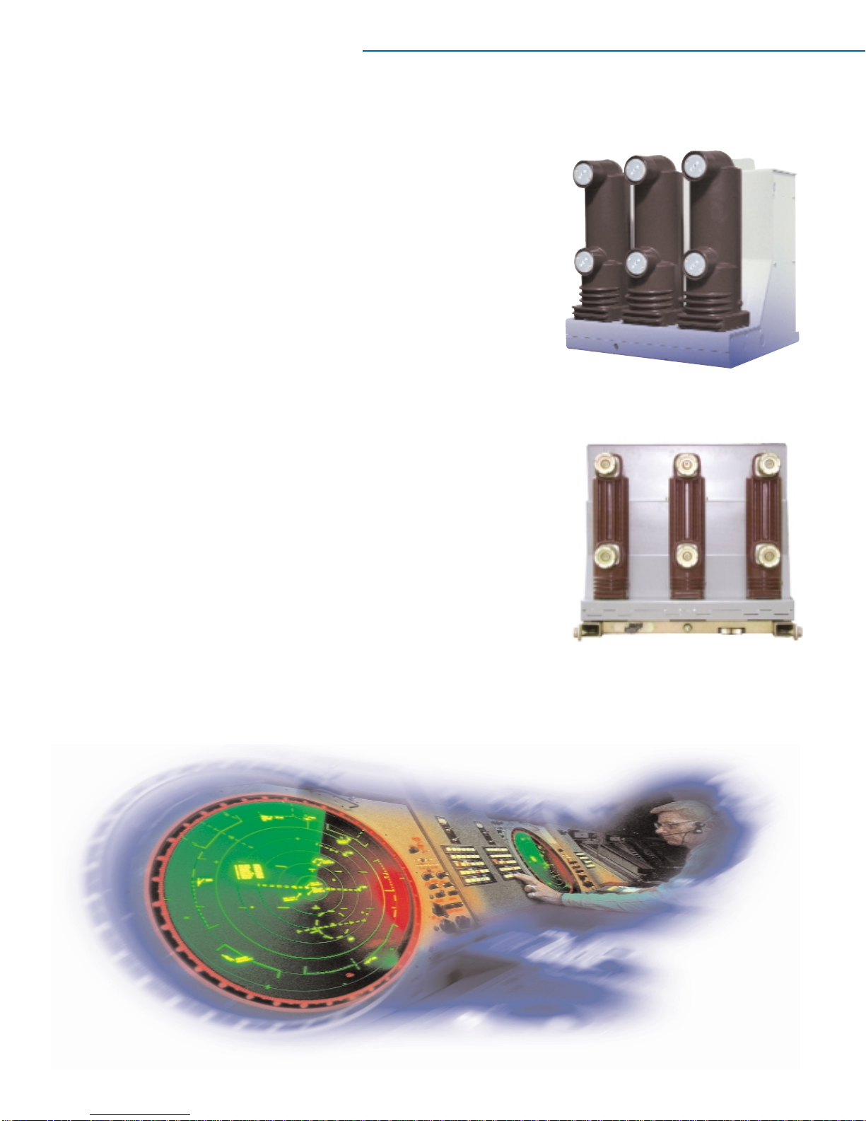
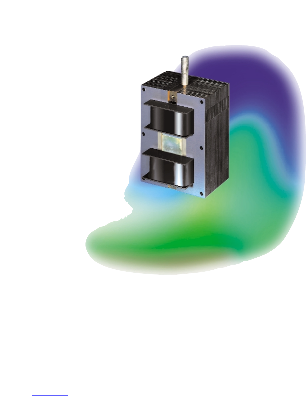
The Circuit breaker shall be an ABB AMVAC or approved equal, three-pole,
drawout (or stationary) type, electrically operated with stored energy magnetic
actuator operating mechanism. The circuit breaker is intended for use as a
general purpose device in accordance with the latest revisions of the
following ANSI standards applying to 5, 15, or 27 kV
applications: ANSI C37.04, C37.06, and C37.09.
Option: Definite purpose or non-standard ratings are
required in accordance with project data sheets, and
availability is confirmed in writing with the vendor.
Definite purpose ratings shall be in accordance with the
latest revisions of the following ANSI standards: C37.04,
C37.06, and C37.09. Circuit breakers of this same type,
rating and control features shall be electrically and
mechanically interchangeable.
Drawout Circuit Breaker Racking System and
Interlocks
The circuit breaker shall be inserted and withdrawn by
means of a breaker mounted racking system, which
can be operated with the compartment door open or
closed. The racking system shall provide smooth
consistent racking, and shall secure the breaker
from both sides of the cell in all racking
positions. During racking, the breaker shall
automatically open and close cell-mounted
safety shutters to cover stationary primary
contacts when the breaker is not in the
“Connected” position.
The racking system shall have
three distinct positions. In
addition to the withdrawn
position (free movement):
“Disconnected” (both
primary and secondary
contacts disengaged), “Test”
(primary contacts disconnected and
shutter closed), and “Connected” (primary and
secondary contacts engaged). Positive stops shall be provided for all three positions, with deliberate operator intervention required to
enable continued insertion or withdrawal of the circuit breaker from any position. The racking system and all moving parts of the
breaker-cell interface, including the secondary coupler, shutter actuator and ground contact, shall be capable of 500 complete
rack-in/rack-out operations without maintenance.
It shall not be possible to insert or withdraw a closed breaker, and the breaker shall not be allowed to close within a cell unless it is in the
“Connected”, “Test”, or “Disconnected” position. Electrical and mechanical blocking means shall be employed to preclude breaker
contact closure in any position other than “Connected”, “Test”, or “Disconnected”. The stored energy capacitors shall be automatically
discharged in the “Disconnected” position prior to removing the circuit breaker from the circuit breaker compartment.
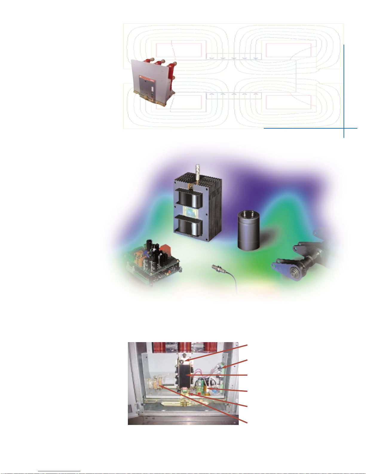
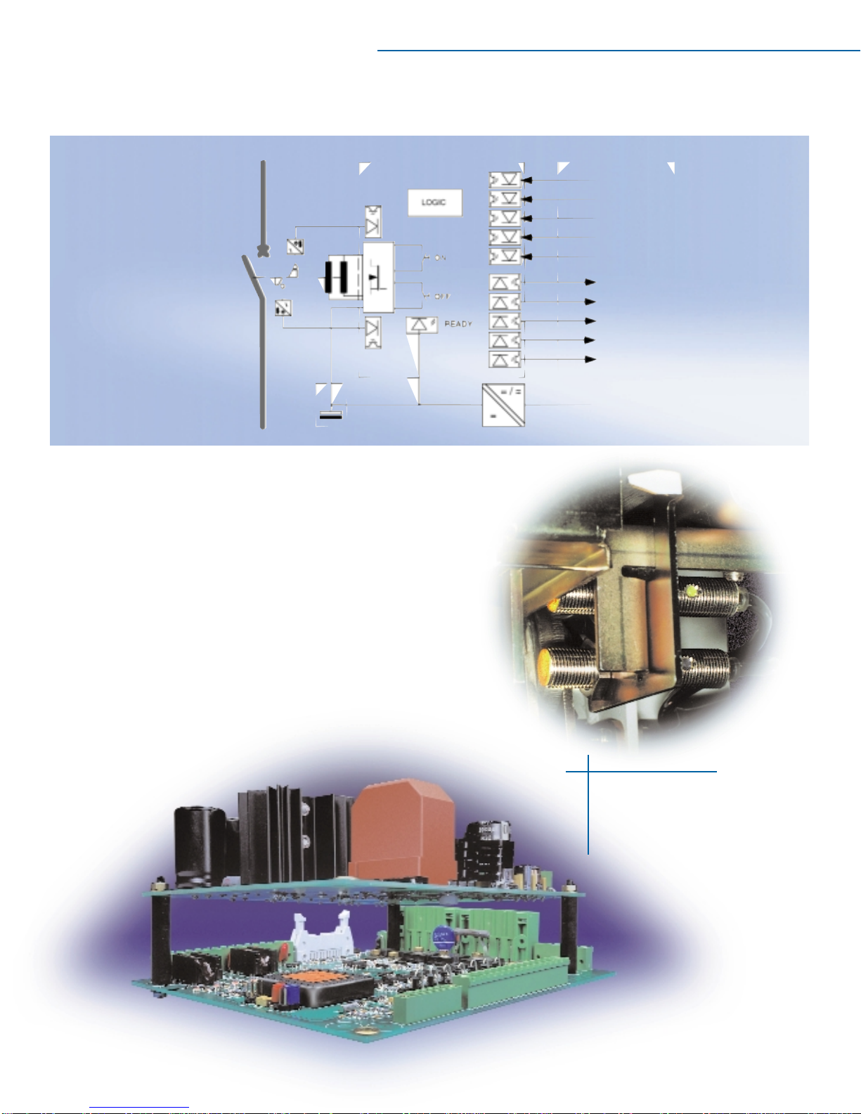
Controls
Opening and closing speed shall be independent of the operator or of the control voltage within the rated control voltage range. Circuit
breaker charge, close, and trip circuits shall be electrically separated, and control voltage for each circuit shall be independently selectable
from the full range of ANSI preferred control voltages. Manual provisions shall be provided for tripping the circuit breaker. These
provisions shall be installed and easily accessible at the front of the breaker.
AMVAC. Circuit breaker specifier's guide.