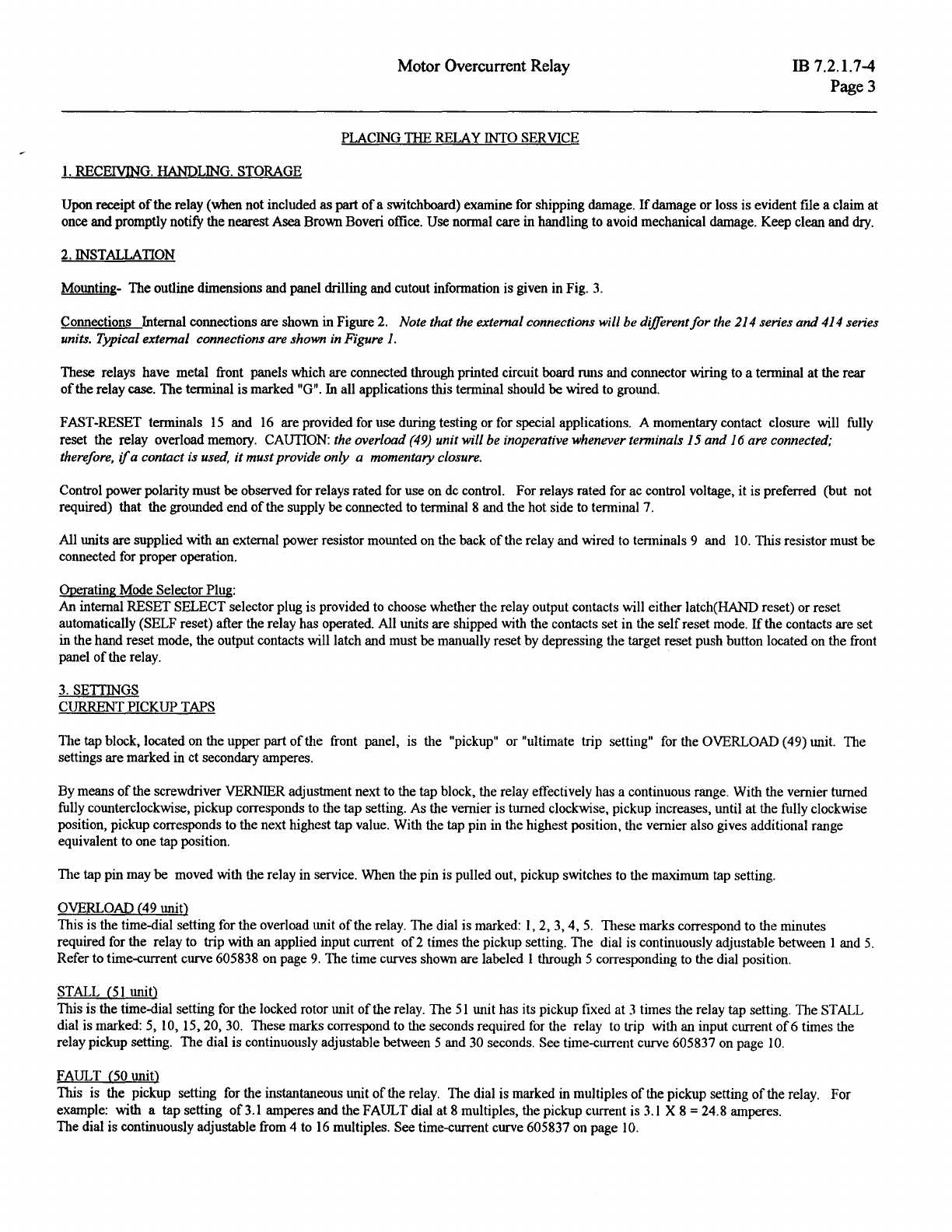
Motor Overcurrent Relay
PLACING
1HE
RELAY INTO SERVICE
1.
RECEIVING. HANDLING. STORAGE
IB 7.2.1.7-4
Page3
Upon receipt
of
the relay (when not included
as
part
of
a switchboard) examine for shipping damage.
If
damage or loss is evident file a claim at
once and promptly notify the nearestAsea Brown Boveri office. Use normal care in handling to avoid mechanical damage. Keep clean and
dry.
2. INSTALLATION
Mounting- The outline dimensions and panel drilling and cutout information is given in Fig.
3.
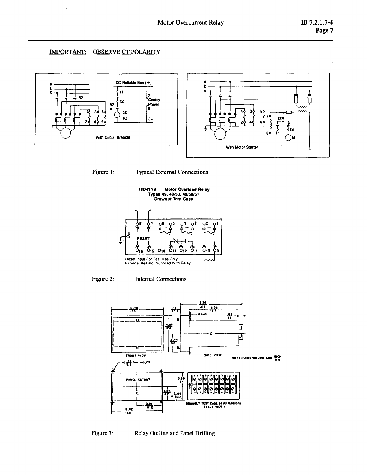
Connections Internal connections are shown in Figure 2. Note that the external connections will be different
for
the 214 series
and
414 series
units. Typical external connections are shown in Figure
1.
These relays have metal front panels which are connected through printed circuit board runs and connector wiring to a terminal
at
the rear
of
the relay case. The terminal is marked "G".
In
all applications this terminal should be wired
to
ground.
FAST-RESET terminals
15
and
16
are provided for use during testing or for special applications. A momentary contact closure will fully
reset the relay overload memory. CAUTION: the overload (49) unitwill be inoperative
when1..'Ver
terminals 15
and
16
are connected;
therefore,
if
a contact is used,
it
mustprovide only a momentary closure.
Control power polarity must be observed for relays rated for use on de control. For relays rated for ac control voltage,
it
is preferred (but not
required) that the grounded end
of
the supply be connected to terminal 8 and the hot side to tenninal 7.
All units are supplied with an external power resistor mounted on the back
of
the relay and wired to tenninals 9 and
10.
Tilis resistor must be
connected for proper operation.
Ooerating Mode Selector Plug:
An internal RESET SELECT selector plug is provided
to
choose whether the relay output contacts will either Iatch(HAND reset) or reset
automatically (SELF reset) after the relay has operated. All units are shipped with the contacts set in the
self
reset mode.
If
the contacts are set
in the hand reset mode, the output contacts will latch and must be manually reset by depressing the target reset push button located on the front
panel
of
the relay.
3.
SETTINGS
CURRENT PICKUP TAPS
The tap block, located on the upper part
of
the front panel, is the "pickup" or "ultimate trip setting" for the OVERLOAD (49) unit. The
settings are marked in ct secondary amperes.
By means
of
the screwdriver VERNIER adjustment next to the tap block, the relay effectively has a continuous range. With the vernier turned
fully counterclockwise, pickup corresponds to the tap setting. As the vernier is turned clockwise, pickup increases, until
at
the fully clockwise
position, pickup corresponds to the next highest tap value. With the tap pin in the highest position, the vernier also gives additional range
equivalent to one tap position.
The tap pin may be moved with the relay in service. When the pin is pulled out, pickup switches
to
the maximum tap setting.
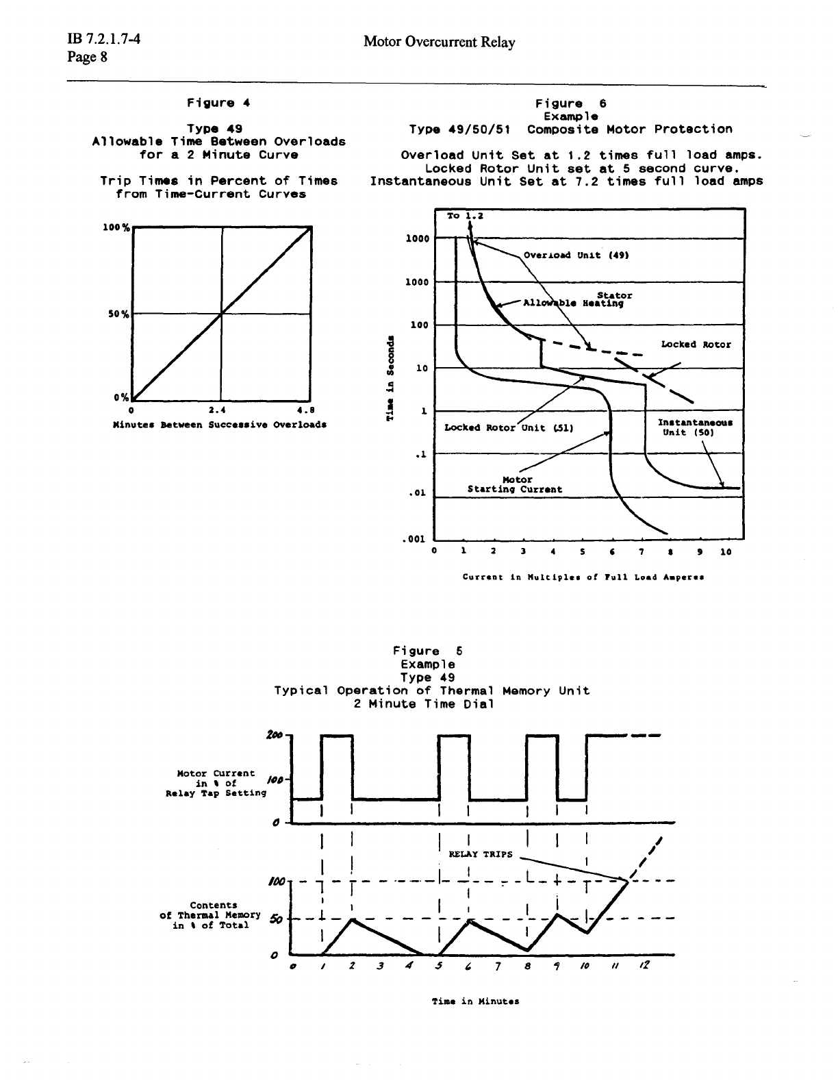
OVERLOAD (49 unit)
This is the time-dial setting for the overload unit
of
the relay. The dial is marked:
l,
2, 3, 4,
5.
TI1ese
marks correspond to the minutes
required for the relay to trip with an applied input current
of2
times the pickup setting. The dial is continuously adjustable between l and
5.
Refer to time-current curve 605838 on page
9.
The time curves shown are labeled I through 5 corresponding to the dial position.
STALL (51 unit)
This is the time-dial setting for the locked rotor unit
of
the relay. The
51
unit has its pickup fixed at 3 times the relay tap setting. The STALL
dial is marked: 5, 10, 15, 20, 30. These marks correspond to the seconds required for the relay
to
trip with an input current
of
6 times the
relay pickup setting. The dial is continuously adjustable between 5 and 30 seconds. See time-current curve 605837 on page
10.
FAULT (50 unit)
This is the pickup setting for the instantaneous unit
of
the relay. The dial is marked in multiples
of
the pickup setting
of
the relay. For
example: with a tap setting
of3.l
amperes and the FAULT dial
at
8 multiples, the pickup current is
3.1X8
= 24.8 amperes.
The dial is continuously adjustable from 4 to
16
multiples. See time-current curve 605837 on page I
0.