ABB TA200DU User manual

—
OPERATING INSTRUCTION
Thermal overload relays TA200DU
ATEX
003 DE
Betriebsanleitung Thermisches Überlastrelais für
explosionsgefährdete Bereiche
006 EN
Operating instructions for thermal overload relay
for potentially explosive areas
009 ES
Manual de instrucciones relé térmico de sobrecarga
para áreas potencialmente explosivas
012 FR
Instructions de service relais thermique pour zones
explosibles
015 IT
Istruzioni per l'uso relè termico per zone a rischio
d'esplosione
018 SV
Bruksanvisning för Termiskt överlastrelä för
explosionsfarliga omgivningar
021 CN
用于有爆炸危险区域的热过载继电器使用说明书
024 RU
Руководство по эксплуатации теплового реле
перегрузки для взрывоопасных зон
PTB 02 ATEX 3045
II (2) G

32CDC106006M5702- OPERATING INSTRUCTION - TA200DU ATEX
Sicherheitshinweise
• Montage und Installation dürfen nur von aus-
gebildetem Fachpersonal, nach den anerkan-
nten technischen Regeln, Vorschriften und
relevanten Normen vorgenommen werden!
• Ungenügend angezogene Klemmschrauben
führen zu unzulässiger Erwärmung!
• Die zulässigen Umgebungsbedingungen sind zu
beachten (siehe technische Daten und Katalog).
• Geräte, die sichtbare Transportschäden auf-
weisen, dürfen nicht eingesetzt werden
—
Thermisches Überlastrelais für
explosionsgefährdete Bereiche
TA200DU
Warnung! Gefährliche Spannung!
Allgemeine Beschreibung
Die erhöhte Gefahr bei Einsatz der Geräte in
explosionsgefährdeten Bereichen verlangt die
konsequente Beachtung folgender Hinweise
und Normen:
• IEC/EN 60079-0 Explosionsfähige Atmosphäre
–Teil 0: Allgemeine Anforderungen
• IEC/EN 60079-1 Explosionsfähige Atmosphäre –
Teil 1: Geräteschutz durch druckfeste
Kapselung „d“
• IEC/EN 60079-7 Explosionsfähige Atmosphäre –
Teil 7: Geräteschutz durch erhöhte Sicherheit „e“
• IEC/EN 60079-14 Explosionsfähige Atmosphäre
- Teil 14: Projektierung, Auswahl und Errichtung
elektrischer Anlagen
• IEC/EN 60079-17 Explosionsfähige Atmosphäre
- Teil 17: Prüfung und Instandhaltung
elektrischer Anlagen
• IEC/EN 60079-31 Explosionsfähige Atmosphäre
–Teil 31: Geräte-Staubexplosionsschutz durch
Gehäuse
• EN 50495 Sicherheitseinrichtungen für
den sicheren Betrieb von Geräten im
Hinblick auf Explosionsgefahren
Das thermische Überlastrelais TA200DU ist
zugelassen unter Gerätegruppe II, Kategorie (2) im
Bereich „G“(Bereiche, in denen explosionsfähige
Gas-, Dampf-, Nebel-, Luft-Gemische vorhanden
sind)
PTB 02 ATEX 3045
II (2) G
Das thermische Überlastrelais TA200DU ist nicht
für die Aufstellung bzw. den Betrieb im explo-
sionsgefährdeten Bereich geeignet. Bei Verwend-
ung in explosionsgefährdeten Bereichen müssen
die Geräte durch entsprechende Maßnahmen der
erforderlichen Zündschutzart entsprechen.
Für Starterkombinationen mit TA200DU und
Motorschhützen der AF-Reihe ist ein geeigneter
Kurzschlussschutz zur Erlangung einer
Zuordnungsart „2“ nach EN 60947-4-1 zu wählen.
Entsprechende Informationen bezüglich geprüfter
Starterkombinationen werden von ABB online
bereitgestellt: siehe „Coordination tables for
motor protection“
http://applications.it.abb.com/SOC/Page/
Selection.aspx

2CDC106006M5702- OPERATING INSTRUCTION - TA200DU ATEX 4
Hinweise
• Bei Ex-Anwendungen ist ein Nachweis der
Wirksamkeit der installierten Schutzeinrichtungen
vor der Inbetriebnahme erforderlich!
• Die Schutzfunktion des Gerätes ist der
thermische Überlastschutz von Motoren.
Im Überlastfall wird der Motor, durch Öffnen
des NC-Kontaktes des elektromechanischen
Überlastrelais abgeschaltet.
• Der sichere Zustand ist ein geöffneter
NC-Kontakt des Gerätes, über den
das Lastschütz gesteuert wird.
Montage und Inbetriebnahme
Der Austausch des TA200DU darf nur durch ein
gleichwertiges, den Vorschriften entsprechend
gekennzeichnetes Gerät erfolgen.
In Anwendungen zum Schutz von Motoren in
explosionsgefährdeten Bereichen, darf das
Gerät nur mit Einstellung „manuelles Rücksetzen“
betrieben werden.
• Einstellung des Motornennstroms
am frontseitigen Einstellknopf.
Hierzu am TA200DU die Einstellung auf
den Nennstromwert des Motors, gemäß
Vorgabe EG-Baumusterprüfbescheinigung
bzw. Typenschild vornehmen.
Bei der Auswahl des Überlastrelais ist die Eignung
anhand der Auslösekennlinien bzw. Auslöseklasse
zu überprüfen. Maßgebend sind die Werte für das
Verhältnis Motoranlauf IAzu Motornennstrom IN
und die kürzeste tE-Zeit, die in der ATEX-Konfor-
mitätsbescheinigung oder in der EG-Baumuster-
prüfbescheinigung und auf dem Typenschild des
Motors vermerkt sein müssen. Das Thermische
Überlastrelais muss innerhalb der tE-Zeit
auslösen, d. h., die Auslösekennlinie aus kaltem
Zustand muss unterhalb des Koordinatenpunktes
IA/IN und der tE-Zeit verlaufen.
Die Anschlussleitungen sind entsprechend den
Vorgaben, bzw. den anzuwendenden Normen
zu dimensionieren.
Sicherheitsdaten TA200DU
Gemäß DIN EN 50495 können an eine
Sicherheitseinrichtung für die Kategorie 2G die
Anforderungen an ein SIL1 und eine HFT = 0
gestellt werden. Das thermische Überlastrelais
der Baureihe TA200DU kann als Komponente einer
Sicherheitseinrichtung, z. B. zusammen mit
einem geeigneten Lastsschütz, diese
Anforderungen erfüllen.

52CDC106006M5702- OPERATING INSTRUCTION - TA200DU ATEX
11.2 1.5 246810 15 20 30 40 60 80
2
1
20
10
1
2
3
4
5
50
40
30
20
10
7
5
4
3
2
1
0.1
0.05
0.005
0.01
I
e
Std
s
min
3 100 x
7.2
47,4 s
15,8 s
tripping time
three pole
3 x Ie
5 x Ie
7.2 x Ie
multiples of rated current
20,0 s
4,3 s
7,6 s
two pole
three pole
Imin
two pole
fuse 315 A gL.
tripping time t
multiples of rated current Ie
Imin 130 A Imax 175 A
8,6 s
31,8 s
11,6 s
6,4 s
three pole
Imax
EN Multiples of rated current Tripping time 2-pole 3-pole Fuse
DE Vielfaches vom Nennstrom Auslösezeit 2-polig 3-polig Sicherung
TA200DU
Die technischen Daten und Kennlinien für weitere Strombereiche finden Sie auf unserer Internetseite
https://library.abb.com/r?cid=9AAC100113&q=TA200DU
Für Nennströme zwischen dem 3- und 8-fachen des Einstellwertes beträgt die Toleranz ±20%
Beispiel zur Ermittlung eines geeigneten Überlastrelais:
Der Motor mit erhöhter Sicherheit hat folgende Daten:
400 V, 50 Hz/60Hz, 77 kW, Ie= 132 A, IA/IN= 7,3, Temperaturklasse T3, tE-Zeit = 13 s
Nach unten stehender Auslösekurve liegt die Auslösezeit unterhalb der tE-Zeit des Motors.

2CDC106006M5702- OPERATING INSTRUCTION - TA200DU ATEX 6
Safety instructions
• Mounting and installation may only be done
by trained technical personnel, according to
the recognized technical rules, regulations,
and relevant standards!
• Insufficiently tightened locking screws lead
to an inadmissible rise in temperature!
• Always observe the permitted ambient
conditions (see technical data and catalog).
• Devices with visible transport damage
must not be used.
—
Thermal overload relay for
potentially explosive areas
TA200DU
Warning! Hazardous voltage!
General description
The extended risks when using these devices in
potentially explosive areas requires consistent
adherence to the following notes and standards:
• IEC/EN 60079-0 Explosive atmospheres –Part
0: General requirements
• IEC/EN 60079-1 Explosive atmospheres –Part 1:
Equipment protection by flameproof
enclosure "d"
• IEC/EN 60079-7 Explosive atmospheres –Part 7:
Equipment protection by increased safety "e"
• IEC/EN 60079-14 Explosive atmospheres - Part
14: Electrical installations design, selection
and erection
• IEC/EN 60079-17 Explosive atmospheres - Part
17: Electrical installations inspection and
maintenance
• IEC/EN 60079-31 Explosive atmospheres –Part
31: Equipment dust ignition protection by
enclosure
• EN 50495 Safety devices required for the safe
functioning of equipment with respect to
explosion risks
The TA200DU thermal overload relay is authorized
under device group II, category (2) in the "G" area
(areas with potentially explosive gas, steam,
smoke or air mixtures).
PTB 02 ATEX 3045
II (2) G
The TA200DU thermal overload relay is not suit-
able for installation and/or operation in poten-
tially explosive areas. When using the devices in
potentially explosive areas, preventive measures
must be taken, e. g. within suitable enclosure.
For starter combinations with TA200DU devices
and AF motor contactors appropriate protection
against short-circuit is to be selected for reaching
coordination type "2" according to EN 60947-4-1.
Information regarding verified starter combina-
tions is provided online by ABB.
see "Coordination tables for motor protection"
http://applications.it.abb.com/SOC/Page/
Selection.aspx

72CDC106006M5702- OPERATING INSTRUCTION - TA200DU ATEX
Notes
For explosion-proof applications, the efficiency
of the installed protection devices has to be
verified prior to commissioning!
• The protection function of the device is the
thermal overload protection of motors. In case
of an overload trip, the motor is switched off by
opening the NC contact of the electromechanical
overload relay.
• The safe state is an open NC contact of the
device used to control the load contactor.
Mounting and commissioning
The TA200DU may only be replaced by an equivalent
device, marked in accordance with the regulations.
For applications protecting motors in potentially
explosive areas, the device may only be used if it
is configured for "manual reset".
• Setting the rated motor current is done
using the adjusting knob on the front side.
For this purpose, the rated motor current has
to be adjusted on the TA200DU according to the
EC type examination certificate specification
and/or the type plate.
When selecting the overload relay, check its
suitability by means of the trip curves and/or
the trip class. Decisive values are the ratio
between the motor startup current IAand the
rated motor current IN, as well as the shortest
time tE. These values have to be marked in the EC-
type examination certificat or in the EC type
examination certificate and on the type plate of
the motor. The thermal overload relay must trip
within the time tE. This means that the trip
curve from the cold state has to be below
the coordination point IA/INand the time tE.
The connecting cables have to be dimensioned
according to the specifications and/or the
applicable standards.
Safety specifications TA200DU
According to DIN EN 50495, the requirements
for a SIL 1 and a HFT = 0 can be placed on
safety equipment for categories 2G
The TA200DU thermal overload relay can meet
these requirements if used as a component of the
safety equipment, e.g. in cooperation with a
suitable load contactor.

2CDC106006M5702- OPERATING INSTRUCTION - TA200DU ATEX 8
TA200DU
The technical specifications and charateristic curves for each current range can be found on our website
https://library.abb.com/r?cid=9AAC100113&q=TA200DU. For nominal currents between three and eight times the set-
point, the tolerance is +/- 20%
Example for the determination of a suitable overload relay:
The motor with enhanced safety has the following data:
400 V, 50 Hz/60Hz, 77 kW, Ie= 132 A, IA/IN= 7.3, temperature class T3, time tE= 13 s
According to the tripping curve below , the trip time is smaller than the time tEof the motor.
11.2 1.5 246810 15 20 30 40 60 80
2
1
20
10
1
2
3
4
5
50
40
30
20
10
7
5
4
3
2
1
0.1
0.05
0.005
0.01
I
e
Std
s
min
3 100 x
7.2
47,4 s
15,8 s
tripping time
three pole
3 x Ie
5 x Ie
7.2 x Ie
multiples of rated current
20,0 s
4,3 s
7,6 s
two pole
three pole
Imin
two pole
fuse 315 A gL.
tripping time t
multiples of rated current Ie
Imin 130 A Imax 175 A
8,6 s
31,8 s
11,6 s
6,4 s
three pole
Imax

92CDC106006M5702- OPERATING INSTRUCTION - TA200DU ATEX
Instrucciones de seguridad
• ¡El montaje y la instalación únicamente deberán
ser efectuados por personal especializado con
la respectiva formación profesional, en confor-
midad con las reglas técnicas reconocidas,
las especificaciones y normas relevantes!
• ¡Tornillos de conexión no apretados suficiente-
mente causarán un calentamiento inadmisible!
• Se deberán observar las condiciones ambien-
tales admisibles (véanse los datos técnicos
y el catálogo).
• No se deberán emplear aquellos dispositivos
que muestren daños de transporte visibles
—
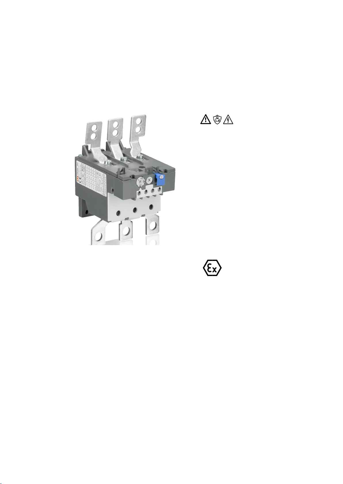
Relé térmico de sobrecarga para
áreas potencialmente explosivas
TA200DU
¡Advertencia! ¡Tensión peligrosa!
Descripción general
Los riesgos al emplear los dispositivos en áreas po-
tencialmente explosivas exigen la observación con-
secuente de las siguientes instrucciones y normas:
• IEC/EN 60079-0 Atmósferas explosivas –Parte
0: Requerimientos generales
• IEC/EN 60079-1 Atmósferas explosivas –Parte
1: Protección de equipos mediante envolvente
antideflagrante "d"
• IEC/EN 60079-7 Atmósferas explosivas –Parte
7: Protección de equipos mediante mayor
seguridad "e"
• IEC/EN 60079-14 Atmósferas explosivas –Parte
14: Diseño, elección y realización de
instalaciones eléctricas
• IEC/EN 60079-17 Atmósferas explosivas –Parte
17: Inspección y mantenimiento de instalaciones
eléctricas
• IEC/EN 60079-31 Atmósferas explosivas –Parte
31: Protección contra explosión de polvo de
equipos mediante carcasa
• EN 50495 Dispositivos de seguridad requeridos
para el funcionamiento seguro de un equipo
respecto a los riesgos de explosión
El relé térmico de sobrecarga TA200DU forma parte
del grupo de dispositivos II, categoría (2) y está ho-
mologado para el uso en entornos de la categoría
"G" (existencia de mezclas explosivas de gas, vapor,
humo o mezclas de aire).
PTB 02 ATEX 3045
II (2) G
El relé térmico de sobrecarga TA200DU no es
apropiado para la instalación o bien el funciona-
miento en áreas potencialmente explosivas.
En caso de su utilización en áreas potencialmente
explosivas, los dispositivos deberán corre-
sponder al tipo de protección requerido
adoptando las medidas correspondientes.
Para las combinaciones de arranque de motor con
TA200DU y contactores de la serie AF se deberá
seleccionar una protección contra cortocircuitos
apropiada para obtener el tipo de asignación "2"
según EN 60947-4-1.
ABB pone a disposición los datos referentes a
combinaciones comprobadas de motores de
arranque en Internet:
véase "Coordination tables for motor protection"
http://applications.it.abb.com/SOC/Page/
Selection.aspx

2CDC106006M5702- OPERATING INSTRUCTION - TA200DU ATEX 10
Notas
• ¡En el caso de aplicaciones Ex, se requerirá la
demostración de la eficacia de los dispositivos
de protección instalados antes de la puesta
en funcionamiento!
• La función de protección del dispositivo es la
protección de sobrecarga térmica de motores.
En caso de sobrecarga, el motor será apagado
mediante la apertura del contacto NC del relé
de sobrecarga electromecánico.
• El estado seguro es el contacto NC abierto
del dispositivo, a través del cual se controla
el contactor de carga.
Montaje y puesta en funcionamiento
La sustitución del TA200DU únicamente deberá
ser
realizada con algún dispositivo equivalente, mar-
cado en concrdancia con las normativas vigentes.
En aplicaciones para la protección de motores en
áreas potencialmente explosivas, el dispositivo
únicamente deberá ser operado con el ajuste
"reset manual".
• Ajuste de la corriente nominal del motor a
través del botón de ajuste en el lado frontal.
Para esto, efectuar el ajuste del valor de
corriente nominal del motor en el TA200DU
según la especificación del certificado de
examen CE de tipo o bien de la placa de
características.
Al seleccionar el relé de sobrecarga, se deberá
comprobar su idoneidad a base de las curvas
características de disparo o bien la clase de
disparo. Prevalecerán los valores para la relación
de corriente de arranque del motor IAy corriente
nominal del motor INy el tiempo tE más corto, los
cuales deberán estar anotados en el certificado
de conformidad tipo EC o en el certificado de
examen CE de tipo y en la placa de características
del motor. El relé térmico de sobrecarga deberá
disparar dentro del tiempo tE, es decir que la
curva característica de disparo desde el estado
frío deberá desarrollarse por debajo del punto
de coordenadas IA/INy el tiempo tE.
Los cables de conexión deberán ser
dimensionados en conformidad con las
especificaciones o bien las normas aplicables.
Datos de seguridad TA200DU
Según DIN EN 50495, los requerimientos para un
SIL1 y HFT=0 deben ser satisfechos en dispositivos
de seguridad categoría 2G.
El relé térmico de sobrecarga de la serie TA200DU,
como componente de un dispositivo de seguridad,
puede satisfacer estas exigencias, p. ej. con un
contactor de carga apropiado.

11 2CDC106006M5702- OPERATING INSTRUCTION - TA200DU ATEX
TA200DU
Los datos técnicos y las curvas características para otros rangos de corriente se encuentran en nuestra página
web https://library.abb.com/r?cid=9AAC100113&q=TA200DU Para corrientes nominales entre 3 y 8 veces el valor de
ajuste, la tolerancia será de ±20%
Ejemplo para la determinación de un relé de sobrecarga adecuado:
El motor con seguridad aumentada presenta los siguientes datos:
400 V, 50 Hz/60Hz, 77 kW, Ie = 132 A, IA/IN= 7,3, clase de temperatura T3, tiempo tE= 13 s
Según la curva de disparo indicada más abajo, el tiempo de disparo se encuentra por debajo del tiempo tEdel motor.
11.2 1.5 246810 15 20 30 40 60 80
2
1
20
10
1
2
3
4
5
50
40
30
20
10
7
5
4
3
2
1
0.1
0.05
0.005
0.01
I
e
Std
s
min
3 100 x
7.2
47,4 s
15,8 s
tripping time
three pole
3 x Ie
5 x Ie
7.2 x Ie
multiples of rated current
20,0 s
4,3 s
7,6 s
two pole
three pole
Imin
two pole
fuse 315 A gL.
tripping time t
multiples of rated current Ie
Imin 130 A Imax 175 A
8,6 s
31,8 s
11,6 s
6,4 s
three pole
Imax
EN Multiples of rated current Tripping time 2-pole 3-pole Fuse
ES Múltiplos de la corriente nominal tiempo de disparo de 2 polos de 3 polos Fusible

2CDC106006M5702- OPERATING INSTRUCTION - TA200DU ATEX 12
Consignes de sécurité
• Le montage et l’installation doivent être ex-
écutés exclusivement par du personnel qualifié
et dûment formé, selon les réglementations
techniques applicables et en respectant les
normes en vigueur !
• Des vis de serrage insuffisamment serrées
peuvent provoquer un échauffement excessif !
• Respecter les conditions ambiantes admissibles
(cf. Caractéristiques techniques et catalogue).
• Ne pas utiliser les appareils qui présentent des
dommages visibles dus au transport.
—
Relais de surcharge thermique
pour zones explosives
TA200DU
Avertissement! Tension électrique
dangereuse!
Description générale
Le risque accru lors de l‘utilisation des appareils
en zones explosives demande le respect strict
des consignes et normes suivantes :
• IEC/EN 60079-0 Atmosphères explosives –
Partie 0 : Exigences générales
• IEC/EN 60079-1 Atmosphères explosives –
Partie 1 : Protection du matériel par enveloppes
antidéflagrantes « d »
• IEC/EN 60079-7 Atmosphères explosives –
Partie 7 : Protection de l’équipement par
sécurité augmentée « e »
• IEC/EN 60079-14 Atmosphères explosives –
Partie 14 : Conception, sélection et construction
des installations électriques
• IEC/EN 60079-17 Atmosphères explosives –
Partie 17 : Inspection et maintenance des
installations électriques
• IEC/EN 60079-31 Atmosphères explosives –
Partie 31 : Protection du matériel contre
l’inflammation des poussières par enveloppe
• EN 50495 Dispositifs de sécurité nécessaires
pour le fonctionnement sûr d’un matériel vis-à-
vis des risques d’explosion
Le relais de surcharge thermique TA200DU est
certifié pour le groupe d‘appareils II, catégorie
(2) dans la zone « G » (zones où se trouvent
des mélanges explosifs de gaz, de vapeur,
de brouillard et d‘air).
PTB 02 ATEX 3045
II (2) G
Le relais de surcharge thermique TA200DU n‘est
pas approprié pour une implantation ou bien
un fonctionnement dans des zones explosives.
En cas d‘utilisation dans des zones explosives, les
appareils doivent être conformes au mode de pro-
tection requis en prenant les mesures appropriées.
Pour des ensembles démarreurs avec relais de sur-
charge thermique TA200DU et contacteurs de la
série AF sélectionner une protection contre les
courts-circuits approprié pour assurer une coordi-
nation de type « 2 » selon la norme EN 60947-4-1.
Des informations supplémentaires relatives
aux ensembles démarreurs certifiés sont
disponibles en ligne :
cf. « Coordination tables for motor protection »
http://applications.it.abb.com/SOC/Page/
Selection.aspx

13 2CDC106006M5702- OPERATING INSTRUCTION - TA200DU ATEX
Notes
• Pour des applications Ex, il est indispensable
de certifier l’efficacité des dispositifs de
protection installés avant la mise en service !
• La fonction de l’appareil est de protéger des
moteurs d’une surcharge thermique. En cas
de surcharge, l’alimentation du moteur sera
coupée en ouvrant le contact NF du relais
de surcharge électromécanique.
• La sécurité est assurée par un contact NF
permettant de commander le contacteur
de charge.
Montage et mise en service
Le remplacement du relais TA200DU‘effectue
toujours par un appareil de même type marqué
conformément aux prescriptions en vigueur.
Dans des applications conçues pour la protection
de moteurs en zones explosives, ne faire
fonctionner l‘appareil qu‘avec le réglage
« Réinitialisation manuelle ».
• Le réglage du courant nominal moteur s’effectue
par rotation du potentiomètre sur la face avant.
Le courant nominal du moteur doit être réglé
conformément aux spécifications CE et/ou aux
données de la plaque signalétique du moteur.
Lors de la sélection du relais de surcharge
thermique, s‘assurer de son adéquation au
besoin à l‘aide des caractéristiques techniques
et de la classe de déclenchement. Les valeurs
à prendre en compte sont le rapport entre le
courant de démarrage moteur IAet le courant
nominal IN, et le temps de déclenchement tE.
Ces valeurs doivent figurer dans le certificat EC
type, ou dans l‘attestation d‘examen CE ou
sur la plaque signalétique du moteur. Le relais
de surcharge thermique doit déclencher dans un
temps inférieur au temps tE, en d‘autre termes,
la courbe de déclenchement à l‘état froid doit
passer en dessous des coordonnées du point
IA/IN; tE(voir exemple).
Le dimensionnement des câbles de raccordement
doit s‘effectuer conformément aux
spécifications ou bien aux normes en vigueur.
Données de sécurité relais TA200DU
Selon la norme DIN EN 50495, un dispositif de
sécurité prévu pour la catégorie 2G doit remplir les
exigences suivantes : SIL1 et HFT = 0.
Le relais de surcharge thermique de la série
TA200DU peut satisfaire à ces exigences comme
composant d‘un dispositif de sécurité, par ex.
conjointement avec un contacteur de charge.

2CDC106006M5702- OPERATING INSTRUCTION - TA200DU ATEX 14
TA200DU
Vous trouverez les caractéristiques techniques et courbes pour d'autres plages d'intensité sur notre site Inter-
net https://library.abb.com/r?cid=9AAC100113&q=TA200DU
La tolérance est de ±20 % pour des courants nominaux entre 3 et 8 fois la valeur de consigne la valeur de consigne
Exemple de détermination d'un relais de surcharge adapté :
Pour un moteur à sécurité renforcée présentant les caractéristiques suivantes :
400 V, 50 Hz/60 Hz, 77 kW, Ie= 132 A, IA/IN= 7,3, classe de température T3, temps tE= 13 s
Selon la courbe de déclenchement ci-dessous, le temps de déclenchement est au-dessous du temps tE du moteur.
11.2 1.5 246810 15 20 30 40 60 80
2
1
20
10
1
2
3
4
5
50
40
30
20
10
7
5
4
3
2
1
0.1
0.05
0.005
0.01
I
e
Std
s
min
3 100 x
7.2
47,4 s
15,8 s
tripping time
three pole
3 x Ie
5 x Ie
7.2 x Ie
multiples of rated current
20,0 s
4,3 s
7,6 s
two pole
three pole
Imin
two pole
fuse 315 A gL.
tripping time t
multiples of rated current Ie
Imin 130 A Imax 175 A
8,6 s
31,8 s
11,6 s
6,4 s
three pole
Imax
EN Multiples of rated current Tripping time 2-pole 3-pole Fuse
FR Multiple du courant de reglage Temps de déclenchement 2 broches 3 broches Fusible

15 2CDC106006M5702- OPERATING INSTRUCTION - TA200DU ATEX
Istruzioni di sicurezza
• Le operazioni di montaggio e installazione sono
riservate a personale specializzato esperto delle
regole della tecnica comunemente accettate,
disposizioni e della relativa normativa!
• Il serraggio non corretto dei morsetti può
provocare un surriscaldamento eccessivo!
• Rispettare le condizioni ambientali ammesse
(si vedano i dati tecnici e il catalogo).
• Non è ammessa l'installazione del dispositivo nel
caso siano presenti evidenti danni da trasporto.
—
Relè di sovraccarico termico
per zone a rischio d’esplosione
TA200DU
Avvertenza! Tensione pericolosa!
Descrizione generale
Il maggior rischio dovuto all’utilizzo dei dispositivi
in zone a rischio d’esplosione richiede il rigoroso
rispetto delle seguenti indicazioni e norme:
• IEC/EN 60079-0 Atmosfere esplosive –Parte 0:
Requisiti generali
• IEC/CEI EN 60079-1 Atmosfere esplosive –Parte
1: Protezione mediante custodia a prova
d’esplosione "d"
• IEC/CEI EN 60079-7 Atmosfere esplosive –Parte
7: Apparecchiature con modo di protezione a
sicurezza aumentata "e"
• IEC/CEI EN 60079-14 Atmosfere esplosive –
Parte 14: Progettazione, scelta e installazione
degli impianti elettrici
• IEC/CEI EN 60079-17 Atmosfere esplosive –
Parte 17: Verifica e manutenzione degli impianti
elettrici
• IEC/CEI EN 60079-31 Atmosfere esplosive –
Parte 31: Protezione contro polveri combustibili
mediante custodia
• EI EN 50495 sistemi di sicurezza negli impianti
con rischio di esplosione
Il relè di sovraccarico termico TA200DU è
omologato per il gruppo dispositivi II, categoria (2)
nell’area "G" (area nella quale sono presenti miscele
di gas, vapore, nebbia e aria deflagranti).
PTB 02 ATEX 3045
II (2) G
Il relè di sovraccarico termico TA200DU non è
idoneo all’utilizzo e al funzionamento in zone
a rischio d’esplosione. In caso di installazione in
zone a rischio d’esplosione, i dispositivi devono
essere dotati del tipo di protezione antidefla-
grante con misure addizionali.
Per le combinazioni con TA200DU e contattori
della Serie AF si dovrà prevedere una protezione
contro corto circuito atta ad ottenere un coordina-
mento "tipo 2" secondo la norma CEI EN 60947-4-
1.
Il database completo delle tabelle di coordinamento
è disponibile sul sito Web ABB: si vedano le
"Coordination tables for motor protection"
http://applications.it.abb.com/SOC/
Page/Selection.aspx

2CDC106006M5702- OPERATING INSTRUCTION - TA200DU ATEX 16
IndicazioniPer applicazioni Ex, prima della messa
in funzione è necessaria la dimostrazione
dell’efficacia delle protezioni installate!
Il relè svolge la funzione di protezione contro
il sovraccarico termico di motori. In caso di
sovraccarico il motore sarà arrestato dall’apertura
del contattore di potenza azionato mediante
l’apertura del contatto NC del relè
elettromeccanico di protezione.
La sicurezza sulla disattivazione del contattore
è garantita dall’apertura del contatto NC
del relè termico.
Installazione e messa in servizio
La sostituzione del relè TA200DU è permessa solo
con un dispositivo equivalente, contrassegnato
come richiesto dalla normativa.
In applicazioni per la protezione di motori in zone
a rischio d’esplosione, l’utilizzo del dispositivo è
permesso solo con l’impostazione "Reset
manuale".
• Impostazione della corrente motore nominale
con il trimmer frontale.
Sul TA2000DU impostare il valore della corrente
nominale del motore in base all’omologazione
di tipo CE risp. alla targhetta conoscitiva.
Per selezionare un relè di sovraccarico adatto,
verificarne l’idoneità in base alle caratteristiche
d’intervento rispondenti alla classe
d’intervento. Sono fondamentali i valori per il
rapporto tra la corrente di avviamento IA e la
corrente motore nominale IN e il l’intervallo
minimo tE che devono essere riportati nella
dichiarazione di conformità EC-Type o
nell’omologazione di tipo CE nonché sulla
targhetta conoscitiva del motore. Il relè di
sovraccarico termico deve intervenire entro
il tempo tE, la caratteristica d’intervento allo
stato a freddo cioè deve essere inferiore alla
coordinata IA/IN e al tempo tE.
Dimensionare i cavi di connessione in base alle
indicazione risp. alla normativa applicabile.
Dati di sicurezza TA200DU
In base alla DIN EN 50495, a un dispositivo di si-
curezza per la categoria 2G si possono richiedere i
requisiti richiesti a un SIL1 e a una HFT = 0.
Il relè di sovraccarico termico della Serie TA200DU
utilizzato in combinazione con un contattore
adeguatamente dimensionato è in grado di
soddisfare questi requisiti.

17 2CDC106006M5702- OPERATING INSTRUCTION - TA200DU ATEX
TA200DU
Per i dati tecnici e le caratteristiche relative ad altri modelli con altre regolazioni si veda la nostra pagina inter-
net:https://library.abb.com/r?cid=9AAC100113&q=TA200DU Per correnti nominali da 3 a 8 volte il valore di regolazi-
one la tolleranza è del ± 20 %
Esempio per la determinazione di un relè di sovraccarico adatto:
Il motore in condizioni di sicurezza maggiori ha le seguenti caratteristiche:
400 V, 50 Hz/60Hz, 77 kW, Ie= 132 A, IA/IN= 7,3, classe di temperatura T3, tempo tE= 13 s
In base alla caratteristica d’intervento sottostante, l’intervallo d’intervento è inferiore al tempo tEdel motore.
11.2 1.5 246810 15 20 30 40 60 80
2
1
20
10
1
2
3
4
5
50
40
30
20
10
7
5
4
3
2
1
0.1
0.05
0.005
0.01
I
e
Std
s
min
3 100 x
7.2
47,4 s
15,8 s
tripping time
three pole
3 x Ie
5 x Ie
7.2 x Ie
multiples of rated current
20,0 s
4,3 s
7,6 s
two pole
three pole
Imin
two pole
fuse 315 A gL.
tripping time t
multiples of rated current Ie
Imin 130 A Imax 175 A
8,6 s
31,8 s
11,6 s
6,4 s
three pole
Imax
EN Multiples of rated current Tripping time 2-pole 3-pole Fuse
IT Multiplo della corrente di regolazione Tempo di apertura Bipolare Tripolare Fusibile

2CDC106006M5702- OPERATING INSTRUCTION - TA200DU ATEX 18
Säkerhetsföreskrifter
• Montering och installation får endast utföras
av utbildad personal, i enlighet med erkända
tekniska regler, föreskrifter och gällande
normer!
• Otillräckligt åtdragna anslutningsskruvar
orsakar otillåten uppvärmning!
• Tillåtna omgivningsförhållanden ska
beaktas (se tekniska data och katalog).
• Enhet som uppvisar synliga transportskador
får inte användas.
—
Termiskt överlastrelä för
explosionsfarliga omgivningar
TA200DU
Varning! Farlig spänning!
Allmän beskrivning
Den ökade risken vid användning av utrustning
i explosionsfarliga miljöer kräver att följande
anvisningar och normer följs konsekvent:
• IEC/EN 60079-0 Explosiv atmosfär - Del 0:
Allmänna fordringar
• IEC/EN 60079-1 Explosiv atmosfär - Del 1:
Utförande med explosionstät kapsling ”d”
• IEC/EN 60079-7 Explosiv atmosfär - Del 7:
Utförande med höjd säkerhet ”e”
• IEC/EN 60079-14 Explosiv atmosfär - Del 14:
Konstruktion, val och utförande av elinstallationer
• IEC/EN 60079-17 Explosiv atmosfär - Del 17:
Kontroll och underhåll av elektriska
installationer
• IEC/EN 60079-31 Explosiv atmosfär - Del 31:
Utrustning i utförande med dammskyddande
kapsling
• EN 50495 Säkerhetsanordningar som fordras
för att utrustningen ska fungera säkert,
med avseende på explosionsrisk
Det termiska överlastreläet TA200DU är godkänt i
enlighet med apparatgrupp II, kategori (2) i område
”G”(områden där det finns explosionsfarliga gas-,
ång-, dim- och luftblandningar).
PTB 02 ATEX 3045
II (2) G
Det termiska överlastreläet TA200DU är inte
lämpligt för uppställning eller drift i explosions-
farliga miljöer. Vid användning i explosionsfarliga
miljöer måste enheten uppfylla kraven för nödvän-
dig antändningstyp.
För startkombinationer med TA200DU och
motorskydd i AF-serien ett lämpligt kortslut-
ningsskydd väljas för att uppnå koordination
typ ”2” enligt EN 60947-4-1.
Motsvarande information gällande koordinerade
startkombinationer kan erhållas från ABB online:
se ”Coordination tables for motor protection”
http://applications.it.abb.com/SOC/Page/
Selection.aspx

19 2CDC106006M5702- OPERATING INSTRUCTION - TA200DU ATEX
Hänvisning
• Vid Ex-användningar krävs att den installerade
skyddsanordningen verifieras före idrifttagning!
• Enhetens skyddsfunktion är termiskt
överbelastningsskydd. Vid överbelastning
kopplas motorn från av kontaktorn genom
att NC-kontakten för elektromekaniska
överlastreläer öppnas.
• Säkert tillstånd för enheten är öppen
NC-kontakt som styrs via lastskyddet.
Montering och idrifttagning
TA200DU får endast bytas mot en likvärdig
enhet som uppfyller föreskrifterna.
Vid användning för skydd av motorer i
explosionsfarliga miljöer får enheten endast tas
i drift med inställningen ”manuell återställning”.
• Ställ in motorns märkström med
inställningsknappen på framsidan.
Ställ in märkströmmen för motorn på TA200DU
i enlighet med uppgifterna i EU-intyget
eller på typskylten.
Vid val av överlastrelä ska lämpligheten kontrolleras
med hjälp av utlösningsriktlinjerna samt utlösning-
sklassen. Värdena för förhållandet mellan mo-
torstartströmmen IA och motormärkströmmen
IN och kortaste tE-tid, som måste vara angivna
på EC-Type intyget, i EU-godkännandet och på mo-
torns typskylt. Det termiska överlastreläet måste
utlösas inom tE-tiden, dvs. utlösningskurvan från
kallt tillstånd måste ligga under koordinatpunk-
terna IA/IN och tE-tiden.
Anslutningsledningarna ska dimensioneras
i enlighet med anläggningsdata, samt
tillämpade standarder.
Säkerhetsdata för TA200DU
Enligt DIN EN 50495 kan kraven
på en SIL1 och en HFT = 0 ställas på en
säkerhetsanordning för kategori 2G
Det termiska överlastreläet i serien TA200DU kan
uppfylla dessa krav som en komponent i en
säkerhetsanordning, t.ex. tillsammans med
en lämplig kontaktor.

2CDC106006M5702- OPERATING INSTRUCTION - TA200DU ATEX 20
TA200DU
Utlösningskarakteristik i kallt tillstånd
https://library.abb.com/r?cid=9AAC100113&q=TA200DU
För märkströmmar mellan tre och åtta gånger inställningsvärdet är toleransen ±20 %
Exempel för bestämning av ett lämpligt överbelastningsrelä:
Motorn med ökad säkerhet har följande data:
400 V, 50/60 Hz, 77 kW, Ie= 132 A, IA/IN= 7,3, temperaturklass T3, tE-tid = 13 s
Enligt nedanstående utlösningskurva ligger utlösningstiden under tE-tiden för motorn.
11.2 1.5 246810 15 20 30 40 60 80
2
1
20
10
1
2
3
4
5
50
40
30
20
10
7
5
4
3
2
1
0.1
0.05
0.005
0.01
I
e
Std
s
min
3 100 x
7.2
47,4 s
15,8 s
tripping time
three pole
3 x Ie
5 x Ie
7.2 x Ie
multiples of rated current
20,0 s
4,3 s
7,6 s
two pole
three pole
Imin
two pole
fuse 315 A gL.
tripping time t
multiples of rated current Ie
Imin 130 A Imax 175 A
8,6 s
31,8 s
11,6 s
6,4 s
three pole
Imax
EN Multiples of rated current Tripping time 2-pole 3-pole Fuse
SV Multipelfaktor för utlösningsström Utlösningstid 2-polig 3-polig Säkring

安全提示
• 只允许经过培训的专业人员按照公认的技术规
则和规定以及相关标准进行装配和安装工作!
• 止动螺钉未拧紧时会导致不允许的升温!
• 请注意允许的环境条件(见技术数据和产品样册)。
• 若在继电器上发现运输损坏,则不得将其投
入使用。
—
用于有爆炸危险区域的热过载继电器
TA200DU
警 告 !电 压 危 险 !
一般描述
由于在有爆炸危险区域中使用继电器时危险加大,
因此请务必遵守以下注意事项和标准:
• IEC/EN 60079-0 爆炸性环境 –第0部 分 :一 般 要 求
• IEC/EN 60079-1 爆炸性环境 –第1部 分 :隔 爆 外
壳“ d”
型设备防护
• IEC/EN 60079-7 爆炸性环境 –第7部 分 :增 加 安 全
性“ e”型 设 备 防 护
• IEC/EN 60079-14 爆炸性环境 –第14部 分 :电 气 设
备 的 设 计 、选 择 和 安 装
• IEC/EN 60079-17 爆炸性环境 –第17部 分 :电 气 设 备
的检查和维护
• IEC/EN 60079-31 爆炸性环境 –第31部 分 :通 过 壳
体的设备粉尘爆炸防护
• EN 50495 涉及爆炸风险的设备安全运行所需的安
全装置
TA200DU热过载继电器被归入第II(2)类 设 备 ,被 许 可
用 于“ G”类 区 域 (存 在 爆 炸 性 气 体 、蒸 汽 、雾 气 、空 气
混和物的区域)和
PTB 02 ATEX 3045
II (2) G
TA200DU热过载继电器不适合在有爆炸危险的区
域中安装或运行。 若要在有爆炸危险的区域中使用,
必须采取合适的措施以使继电器满足相应防点燃
类别的要求。
由TA200DU和AF系列电机接触器组成的组合式
启动器 应选择合适的短路保护,以满足按照
EN 60947-4-1的“ 2”类 要 求 。
有关经检验组合式启动器的信息在ABB网站上提供:
请参阅“电机保护配合表”
http://applications.it.abb.com/SOC/
Page/Selection.aspx
21 2CDC106006M5702- OPERATING INSTRUCTION - TA200DU ATEX
IECEx BVS 17.0074
Table of contents
Languages:
Other ABB Relay manuals