ABB SPAM 150 C Parts list manual

SPCJ 4D34
TRIP
PROGRAM
RESET
STEP
L1 L2 L3
o
IRF
I
II
I
956
SGR 1
SGR 2
SGB
SGF
kc
θ
<
I
I
%
[]
t
Σ
s
[]
si
<
t
s
[]
∆
t
Σ
s/h
[]
s
[]
t
∆
L
I
I
%
[]
∆
o
t
s
[]
>>
t
s
[]
n
II
/
>>
n
s
II
/
s
t
s
[]
n
θ
II
/
6x
t
s
[]
p
[]
%
θ
a
[]
%
θ
i
[]
%
o
I
n
I
[]
%
s
3
I
>
>
3
I
RS 641 Ser.No.
SPAM 150 C
U
aux
SPCJ 4D34
REGISTERS OPER.IND.
0000 0
1
2
3
4
5
6
7
8
n
/
L3
n
/
L1
n
/
L2
1
2
3
4
5
6
7
8
>
>
o
<
2
5
9
EXT.TRIP
9
t
%
[]
%
θ
[]
955D
I
II
II
I
I
I
I
II
80...265V
18...80V –
n=
()
I
I
5A1A
n=
I
()
o
I
5A1A
o
I
n
I
∆
2
θ
a
θ
>
θ
t
θ
>
θ
t
i
i
+
t
Σ
si EINH
+
I
∆
θ
m%
[]
min
[ ]
I
2
t
%
[]
%
[]
L
I
t
I
2
ss
–
~NO
NC
f
n= 50Hz
60Hz
SPAM 150 C
Motor protection relay
User´s manual and Technical description

2
1MRS 750637-MUM EN
Issued 1997-03-05
Modified 2002-04-24
Version B (replaces 34 SPAM 8 EN1)
Checked MK
Approved OL
Data subject to change without notice
SPAM 150 C
Motor protection relay
Contents Characteristics ................................................................................................................ 2
Area of application.......................................................................................................... 3
Short description of operation ........................................................................................ 3
Connection diagram ....................................................................................................... 4
Connections ................................................................................................................... 6
Control signals between the modules .............................................................................. 7
Abbreviations of signal names ......................................................................................... 7
Operation indicators ....................................................................................................... 8
Power supply and output relay module........................................................................... 9
Technical data (modified 2002-04) ............................................................................... 10
Maintenance and repair ................................................................................................ 13
Spare parts .................................................................................................................... 13
Ordering numbers ........................................................................................................ 13
Dimensions and instructions for mounting .................................................................. 14
Information required with order ................................................................................... 14
The complete user´s manual includes the following separate manuals:
Motor protection relay, general description 1MRS 750637-MUM EN
General characteristics of D type relay modules 1MRS 750066-MUM EN
Motor protection relay module type SPCJ 4D34 1MRS 750476-MUM EN
Versatile multifunction relay for the protection
of circuit breaker or contactor controlled a.c.
motors
Flexible single, two or three phase protection
relay for feeders etc.
Thermal overload protection, monitoring all
three phases, the thermal replica is adjustable
both for protected objects with or protected
objects without hot-spots
High-set overcurrent protection operating in-
stantaneously or with definite time characteris-
tic
Phase unbalance & single-phasing protection
with inverse time characteristic
Fast operating incorrect phase sequence protec-
tion
Sensitive definite time or instantaneous earth-
fault protection with tripping or only signalling
function
Characteristics Undercurrent protection with wide start cur-
rent and operate time setting ranges
Start-up supervision with Is2x ts-characteristic,
with a low-set overcurrent unit or as a start-up
time counter. The start-up supervision can also
cooperate with a speed switch on the motor
shaft of an ExE-type motor
Continuous self-supervision of hardware and
software
Current range handled meets the requirements
for ExE motor drives of Zone 1
Two versions; one with a normally open trip
contact for circuit-breaker controlled drives and
another with a normally closed trip contact for
contactor controlled drives
Fibre-optic serial communication over the SPA
bus provides access to any relay data
Powerful support software for parametrization
of the relay and for recording of measured and
recorded values, events, etc.

3
The microprocessor based motor protection
relay SPAM 150 C is an integrated design
current measuring multifunction relay for the
complete protection of a.c. motors. The main
area of application covers large or medium-sized
three-phase motors in all types of conventional
contactor or circuit breaker controlled motor
drives. The motor protection relay is available in
two versions, one with a making trip contact and
the other with a breaking trip contact.
The relay can also be used in other applications
requiring a single-, two- or three-phase over-
current and/or overload protection and non-
directional earth-fault protection.
Area of
application
The combined multifunction motor protection
relay is a secondary relay device which is con-
nected to the current transformers of the pro-
tected motor drive. The three phase currents
and the neutral current of the protected device
are continuously measured and on the basis of
this measurement, the thermal condition of the
motor is calculated and the faults of the network
are detected. In fault situations the protective
units of the relay provide alarm or trip the
circuit-breaker.
By appropriate programming of the output re-
lay matrix, various starting, prior alarm or re-
start inhibit signals are received as contact
functions. This contact information is used e.g.
for the blocking of co-operating protective re-
lays located upstreams, for connection to annun-
ciator units etc.
The motor protection relay contains one exter-
nal logic control input, which is activated by a
control signal on the auxiliary voltage level. The
influence of the control input on the relay is
determined by programming switches of the
measuring module. The control input can be
used either for blocking one or more of the
protective stages, for carrying out an external
trip order, for inhibiting a restart attempt or for
resetting a latched output relay in the manual
reset mode.
Short description
of operation
Fig. 1. Protective functions of the motor protection relay type SPAM 150 C.
The encircled numbers refer to the ANSI-numbering of protective functions.
START
THREE-PHASE THERMAL
OVERLOAD PROTECTION
TRIP
SIGNAL 1
SERIAL PORT
IL1
IL2
IL3
Io
PRIOR ALARM
OR SIGNAL 2
IRF SELF-SUPERV.
CONTROL
INPUT BS
CUMULATIVE START-UP
COUNTER AND RESTART
INHIBIT FUNCTION
SERIAL COMMUNICATION PORT
STALL PROTECTION WITH
SPEED SWITCH INPUT FOR
DRIVES WHERE ts > te
LOW-SET DEFINITE TIME
EARTH-FAULT PROTECTION
RESTART
ENABLE
DEFINITE TIME UNDER-
CURRENT PROTECTION
49
51N
37
46
INCORRECT PHASE SEQUENCE
AND PHASE INVERSE TIME
UNBALANCE PROTECTION
51
THERMAL STRESS SUPERVISION
ALT. THREE-PHASE DEFINITE TIME
OVERCURRENT PROTECTION
14
THREE-PHASE HIGH-SET
DEFINITE TIME OVERCURRENT
PROTECTION
50
48

4
Connection
diagram
SPAM 150 C
63
L1
L2
L3
70 71 72
0
65 66
68 69
77 78
IRF SIGNAL 1
-
+
TRIP
74 75
PRIOR ALARM
SIGNAL 2
80 81
10
11
11
SGB/1
SGB/2
SGB/7
SGB/8
SGB/3
TRIP
R
LATCHING
START
PRIOR ALARM
RESTART
ENABLE
1
I
-
I0
+
+
+
B
+
C
+
F
+
E
+
D
+
A
SGB/4
11
SGR1/8
SGB/5
SGB/6
U1 SPCJ 4D34
U3 SPTE 4E3
U2 SPTU _ R2
CONTROL
INPUT
IRF
Σ >
ts
3
STALL
I/O
I>>
Io>
I<
START
∆I
RESTART
INHIBIT
RESTART
INHIBIT
RELAY RESET
θ>θi
θ>θa
θ>θt
EXTERNAL TRIP
I x t
2
ss
252627
123456789
1 A
5 A
1 A
5 A
1 A
5 A
1 A
5 A
SERIAL
PORT
SPA-ZC_
Rx Tx
61
62
U
+ (~)
- (~)
+-
aux
~
SGR1/7
SGR1/6
SGR1/5
SGR1/4
SGR1/3
SGR1/2
SGR1/1
SGR2/8
SGR2/7
SGR2/6
SGR2/5
SGR2/4
SGR2/3
SGR2/2
SGR2/1
SG4/3
I >
s
SG4/2
TS1 SS1 SS2 SS3 TS2
Fig. 2. Connection diagram of the motor protection relay SPAM 150 C. The version shown is the
one with the normally open trip contact, i.e. with an auxiliary supply and output relay module type
SPTU 240R2 or SPTU 48R2.

5
Uaux Auxiliary voltage
A, B, C, D, E, F Output relays
IRF Self-supervision
SGB Switchgroup for the configuration of the blocking or control signal
TRIP Trip output relay, output 65-66
SIGNAL Signal on tripping
PRIOR ALARM Prewarning for a beginning overload condition
START Start information from the motor
RESTART ENABLE Starting of motor inhibited in fault conditions
U1 Motor protection module SPCJ 4D34
U2 Power supply and output relay module SPTU 240 R2 or SPTU 48 R2
with a normally open trip contact, SPTU 240 R3 or SPTU 48 R3 with
a normally closed trip contact
U3 Input module SPTE 4E3
SPA-ZC— Bus connection module
SERIAL PORT Serial communication port
Rx, Tx Receiver bus terminal (Rx) and the transmitter bus terminal (Tx) of
the bus connection module
STALL External stall control input
RESTART INHIBIT External restart inhibit control signal
LATCHING Latching function of the trip relay
68
69
77
78
80
81
Made in Finland
1
2
3
4
5
6
7
8
9
25
26
27
61
62
63
65
66
74
75
70
71
72
10
11
Serial Port
SPA
Fig. 3. Rear view of relay SPAM 150 C.

6
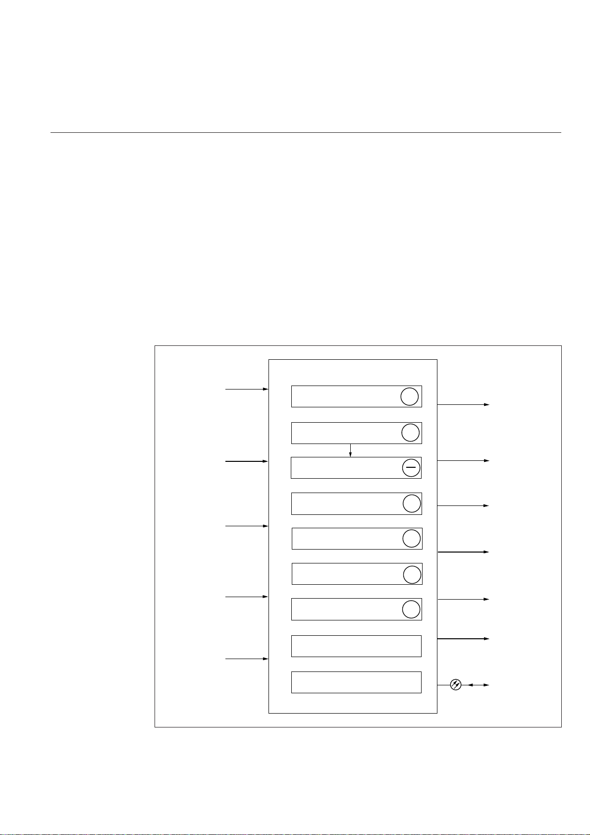
vides a latching function after any trip opera-
tion. After having latched the output relay must
be manually reset or reset by remote control.
The trip alarm signals from the relay module are
obtained via output relays B and C. The signals
to be routed to these relays are selected with
switches1...7 of switchgroup SGR1 and switches
4...8 of switchgroup SGR2 of the relay module.
Normally the output relays B and C are given
such a configuration that a thermal prior alarm
is obtained over relay C and the trip signals of
the protection units are linked to output relay B
to form an auxiliary trip signal. This is also the
default setting of the relay on delivery from the
factory.
The signals to be routed to the output relay D
are selected with switches 1, 2 and 3 of software
switchgroup SGR2 in the main menu of the
relay module. Switch SGR2/1 routes the ther-
mal prior alarm, switch SGR2/2 routes the
startup information for the motor and switch
SGR2/3 routes the start signal of the high-set
overcurrent stage to output relay D.
Output relay E, terminals 74-75, is a heavy duty
output relay capable of controlling a circuit
breaker, as the main trip relay A. Relay E is used
for controlling the restart of the motor. If the
thermal capacity used exceeds the set restart
inhibit level of the thermal unit, if the allowed
maximum cumulative start-up count is exceeded
or if the external restart inhibit signal is active
the output relay E prevents a motor restart
attempt. This also applies to a condition where
the protective relay is out of auxiliary voltage or
the relay is faulty.
Output relay F, terminals 70-71-72, operates as
the output relay of the integrated self-supervi-
sion system. The relay operates on the closed-
circuit principle, thus under normal service con-
ditions the contact gap 70-72 is closed. If a fault
is detected by the self-supervision system, or if
the auxiliary supply fails, the output relay drops
off, providing an alarm signal by closing the NO
contact 71-72.
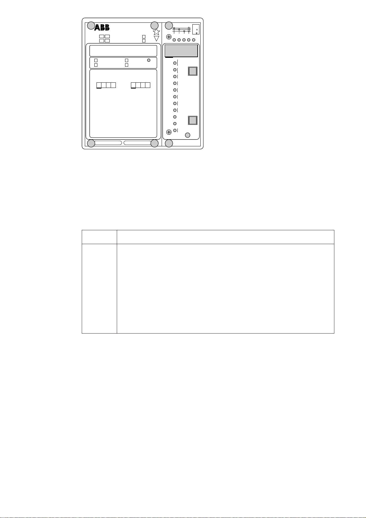
The relay is connected to the SPA data bus by
means of bus connection module type SPA-ZC
17 or SPA-ZC21. The bus connection module
is connected to the D type connector marked
SERIAL PORT on the rear panel of the relay.
The fibre-optic cables are connected to the
connectors Tx and Rx of the bus connection
module. The communication mode selector
switches on the bus connection module are set
in position "SPA".
The three phase currents are connected to ter-
minals 1-2, 4-5 and 7-8, when the rated current
of the secondary circuits is In= 5 A. When using
current transformers with a rated current of 1 A,
terminals 1-3, 4-6 and 7-9 are used. The ther-
mal overload protection may also be used in
single-phase or two-phase applications, in this
case inputs not used may be left unconnected.
To get a proper operation of the unbalance and
incorrect phase sequence protection in a two-
phase application, the two phase currents should
be summed in the third phase current input. In
single-phase applications, wiring the phase cur-
rent through two or three current inputs in series
may slightly increase the operating speed of the
relay and stabilize operation of the thermal unit.
The neutral current of the earth-fault protection
is connected to terminals 25-26 when the rated
current is 5 A and to terminals 25-27 when the
rated current is 1 A.
The control input 10-11 can be used in five
different ways:
- as the control input controlled by a motor
speed switch in Ex-type applications
- as the control input of an external blocking
signal for blocking the operation of the unbal-
ance or earth-fault protection units
- as the control input for an external trip signal
- as the control input for unlatching the trip relay
- as the control input for the restart enable relay.
The designed function is selected by means of
switches 1...8 of switchgroup SGB in the main
menu of the protection relay module.
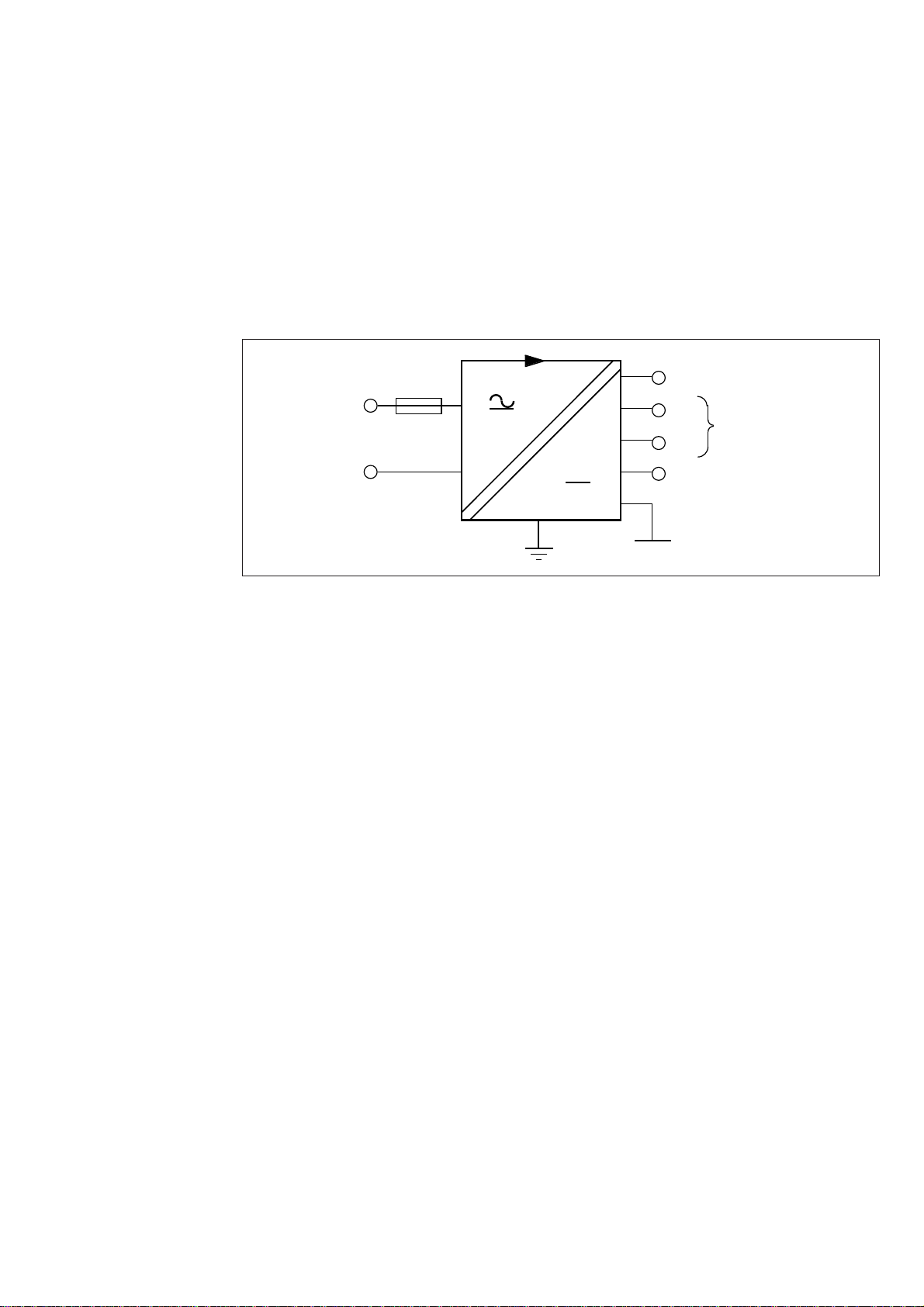
The auxiliary supply voltage of the relay is
connected to the terminals 61-62. At d.c. auxil-
iary supply voltage the positive lead is connected
to terminal 61. The accepted input voltage
range is determined by the type of power supply
and output relay module inserted in the relay
case. For further details see the description of the
power supply module. The accepted auxiliary
voltage range of the relay is indicated on the
front panel.
Output relay A provides the CB tripping com-
mands when the operate time of a protective
unit has elapsed. The earth-fault unit can be
made non-tripping, i.e. only signalling, with
switch 8 of switchgroup SGR1. On delivery from
factory all protective units are selected to per-
form tripping. A latching function of the output
relay A can be selected by means of switches
SGB/7 and SGB/8. Switch SGB/7 gives a latch-
ing function after a short-circuit, an earth-fault
or an unbalance tripping. Switch SGB/8 pro-
Connections

7
Control signals
between the
modules
The figure below schematically illustrates how
the starting, tripping, control and blocking sig-
nals can be programmed to obtain the required
function of the protection relay.
IL1
IL2
IL3
SGR1 / 3
SGR2 / 5
I>, Is
I>> t>>
t>, ts
to>, ko
Io>
Io
BS
SGB / 1
SGB / 2
SGB / 4
SGB / 5
SGB / 6
EXTERNAL TRIP
RELAY RESET
1
SGB / 7
RESET+
PROGRAM
1
SGB / 8
RESET+
PROGRAM
1
SS1
SS2
SPCJ 4D34
TS1
TS2
SS3
RESET
TRIP
A
B
C
D
F
IRF
E
RESTART
ENABLE
START /
PRIOR ALARM
PRIOR ALARM /
SIGNAL 2
SIGNAL1
TRIP
IRF
(AR2)
(AR1)
(AR3)
SPTU ___R2
INTERNAL SIGNAL DIAGRAM
I ,t
Θ
START
i
a
t
Θ
∆It∆
I< t<
RESTART INH.
∑ts
SGR2 / 1
SGR1 / 1
SGR2 / 4
SGR1 / 2
SGR1 / 4
SGR1 / 5
SGR2 / 6
SGR1 / 7
SGR2 / 8
SGR1 / 6
SGR2 / 7
SGR1 / 8
SGR2 / 3
STALL
RESTART
INH.
SGB / 3
SGR2 / 2
1
Θ>Θ
Θ>Θ
Θ>Θ
SG4 / 3
SG4 / 2
6x
Fig. 4. Control signals between the modules of the motor protection relay SPAM 150 C.
the measuring relay module. The functions of
the different switches are explained in the user´s
manual of the measuring module SPCJ 4D34.
The functions of the blocking and starting sig-
nalsare selected with theswitchesof switchgroups
SGF, SGB and SGR. The checksums of the
switchgroups are found in the setting menu of
Abbreviations of
signal names
IL1, IL2, IL3 Phase currents
I0Neutral current
BS Blocking or control Signal
SS1 Start Signal 1
SS2 Start Signal 2
SS3 Start Signal 3
TS1 Trip Signal 1
TS2 Trip Signal 2
AR1...3 Auto-Reclose start signals (not in use in SPAM 150 C)
IRF Internal Relay Fault signal
SGF Switch Group for Functions
SGB Switch Group for Blockings
SGR1...2 Switch Groups for Relay configuration

8
Operation
indicators
B) If the display is dark when one of the protec-
tion stages I>, I>> or I0> operates, the faulty
phase or the neutral path is indicated with a
yellow LED. If, for instance, the TRIP indi-
cator glows red, and the indicators IL1 and
IL2 at the same time are illuminated, over-
current has occurred on phase L1 and L2.
C) Besides being a code number at data presen-
tation, the leftmost red digit in the display
serves as a visual operation indicator. An
operation indicator is recognized by the fact
that the red digit alone is switched on. Nor-
mally the first event to appear is indicated.
For the thermal unit, however, a prior alarm
signal is later replaced by the trip indication,
if tripping is carried out. In order to enable
reading of actual thermal levels etc., it is
possible to acknowledge the indication of
the thermal unit while the unit is still acti-
vated. The same applies to a signalling earth-
fault.In these cases the indications are memo-
rized and reappear when the display is dark.
All operation indicators are automatically
reset when the motor is restarted. The fol-
lowing table, named OPERATION IND.
on the relay front panel, is a key to the
operation indicator code numbers used.
SPCJ 4D34
TRIP
PROGRAM
RESET
STEP
L1 L2 L3
o
IRF
I
II
I
956
SGR 1
SGR 2
SGB
SGF
kc
θ
<
I
I
%
[]
t
Σ
s
[]
si
<
t
s
[]
∆
t
Σ
s/h
[]
s
[]
t
∆
L
I
I
%
[]
∆
o
t
s
[]
>>
t
s
[]
n
II
/
>>
n
s
II
/
s
t
s
[]
n
θ
II
/
6x
t
s
[]
p
[]
%
θ
a
[]
%
θ
i
[]
%
o
I
n
I
[]
%
s
3
I
>
>
3
I
RS 641 Ser.No.
SPAM 150 C
U
aux
SPCJ 4D34
REGISTERS OPER.IND.
0000 0
1
2
3
4
5
6
7
8
n
/
L3
n
/
L1
n
/
L2
1
2
3
4
5
6
7
8
>
>
o
<
2
5
9
EXT.TRIP
9
t
%
[]
%
θ
[]
955D
I
II
II
I
I
I
I
II
80...265V
18...80V –
n=
()
I
I
5A1A
n=
I
()
o
I
5A1A
o
I
n
I
∆
2
θ
a
θ
>
θ
t
θ
>
θ
t
i
i
+
t
Σ
si EINH
+
I
∆
θ
m%
[]
min
[ ]
I
2
t
%
[]
%
[]
L
I
t
I
2
ss
–
~NO
NC
f
n= 50Hz
60Hz
A) The operation indicator TRIP is lit when
one of the protection stages operates. When
the protection stage resets, the red indicator
remains alight.
Indication Explanation
1θ> θa= The thermal level has exceeded the set prior alarm level
2θ> θt= The thermal unit has tripped
3θ> θi, ∑tsi, = The thermal restart inhibit level is exceeded, the startup time
EINH counter is full or the external inhibit signal is active
4 I>> = The high-set stage of the overcurrent unit has tripped
5∆I = The unbalance/incorrect phase sequence protection unit has
tripped
6I
2x t = The start-up stall protection unit has tripped
7I
0= The earth-fault unit has tripped
8 I< = The undercurrent unit has tripped
9 EXT.TRIP = An external tripping has been carried out
D) The TRIP indications persist when the pro-
tective stage returns to normal. The indica-
tor is reset by pushing the RESET/STEP
push-button. A restart of the motor auto-
matically resets the operation indications.
Further, the indicators may be reset via the
external control input 10-11 by applying a
control voltage to the input, provided that
the switch SGB/6 is in position 1.
The basic protective relay functions are not
depending on the state of the operation
indicators, i.e. reset or non-reset. The relay is
permanently operative.
E) In two minutes after the internal self-super-
vision system has detected a permanent relay
fault the red IRF indicator is lit and the
output relay of the self-supervision system
operates. Further, in most fault situations an
autodiagnostic fault code is shown in the
display. The fault code is composed of a red
figure 1 and a green code number, which
indicates the fault type. The fault code can
not be reset as long as the fault persists.
When a fault code appears on the display, the
code number should be recorded on a piece
of paper and given to the authorized repair
shop, when overhaul is ordered.

9
To be able to operate the relay needs a secured
auxiliary voltage supply. The power supply
module forms the voltages required by the meas-
uring relay module and the auxiliary relays. The
withdrawable power supply and output relay
module is located behind the system front panel,
which is fixed by means of four cross-slotted
screws. The power supply and output relay
module contains the power supply unit, all
output relays, the control circuits of the output
relays and the electronic circuitry of the external
control inputs.
The power supply and output relay module can
be withdrawn after removing the system front
panel. The primary side of the power supply
module is protected with a fuse, F1, located on
the PCB of the module. The fuse size is 1 A
(slow).
The power supply unit is a transformer con-
nected, i.e. galvanically isolated primary and
secondary side, flyback-type dc/dc converter. It
forms the dc secondary voltages required by the
measuring relay module; that is +24 V, ±12 V
and +8 V. The output voltages ±12 V and +24
V are stabilized in the power supply module,
while the +5 V logic voltage required by the
measuring relay module is formed by the stabi-
lizer of the relay module.
1 A slow +8V
+12V
-12V
+24V
Uaux
80...265 V ac & dc
18...80 V dc
Unstabilized logics
voltage
Operation amplifier
voltage
Output relay coil
voltage
Fig. 5.Voltage levels of the power supply module.
A green LED indicator Uaux on the system front
panel is illuminated when the power supply
module is in operation. The supervision of the
voltages supplying the electronics is placed in
the measuring module. If a secondary voltage
deviates from its rated too much, a self-supervi-
sion alarm will be established. An alarm is also
established when the power supply module is
withdrawn from the relay case, or when the
auxiliary power supply to the relay is inter-
rupted.
There are two versions of power supply and
output relay modules available. For both types,
the secondary sides and the relay configur-
ations are identical, but the input voltage ranges
differ.
Voltage ranges of the power supply modules:
- SPTU 240R2 or
SPTU 240R3 Uaux = 80...265 V dc/ac
- SPTU 48R2 or
SPTU 48R3 Uaux = 18...80 V dc
The modules SPTU 240 R2 or SPTU 240 R3
can be used with both ac and dc voltages.
Modules SPTU 48 R2 and SPTU 48 R3 are
designed for dc supply only. The auxiliary volt-
age range of the power supply module of the
relay assembly is indicated on the system front
panel.
The module SPTU 240R2 and SPTU 48R2
have a normally open trip contact whereas the
modules SPTU 240R3 and SPTU 48R3 have a
normally closed trip contact.
Power supply
and output relay
module

10
Energizing inputs
Phase and neutral current inputs,
terminals 1-2, 4-5, 7-8, 25-26 1-3, 4-6, 7-9, 25-27
Rated current In5 A 1 A
Thermal withstand capability
- continuously 20 A 4 A
- for 1 s 500 A 100 A
Dynamic current withstand, half-wave value 1250 A 250 A
Input impedance < 20 mΩ< 100 mΩ
Phase current monitoring range 0...63 x In
Neutral current monitoring range 0...210 % In
Rated frequency fn50 Hz / 60 Hz
Output contact ratings
Trip contact and restart enable contact
Contact type *) NO (normally open) NC (normally closed)
Terminals 65-66, 74-75 65-66
- Rated voltage 250 V dc/ac 250 V dc/ac
- Carry continuously 5 A 5 A
- Make and carry for 0.5 s 30 A 10 A
- Make and carry for 3.0 s 15 A 8 A
- Breaking capacity for dc, when the control
circuit time-constant L/R ≤40 ms,
at 48 / 110 / 220 V dc 5 A / 3 A / 1 A 1 A / 0.25 A / 0.15 A
Breaking capacity for ac 5 A 5 A
Signalling contacts
Terminals 70-71-72, 68-69, 77-78, 80-81
- Rated voltage 250 V dc/ac
- Rated current 5 A
- Make and carry for 0.5 s 10 A
- Make and carry for 3.0 s 8 A
- Breaking capacity for dc, when the control
circuit time-constant L/R ≤40 ms,
at 48 / 110 / 220 V dc control circuit voltage 1 A / 0.25 A / 0.15 A
External control inputs
Blocking, remote reset or remote setting input 10-11
External control voltage level 18...265 V dc or 80...265 V ac
Typical control current of input circuit 2…20 mA
Power supply and output relay module
Supply and relay module, type SPTU 240R2/ - R3 80...265 V dc/ac
Supply and relay module, type SPTU 48R2/ - R3 18...80 V dc
Power consumption under quiescent/operating
conditions ~4 W/ ~6 W
Note!
*) The trip contact 65-66 has different contact ratings depending on whether it is a normally open
contact (SPTU 240R2 or SPTU 48R2) or a normally closed contact (SPTU 240R3 or SPTU
48R3).
Technical data
(modified 2002-04)

11
Motor protection relay module SPCJ 4D34
Thermal overload unit
Setting of full load current, Iθ0.5...1.50 x In
Resolution of current setting 0.01 x In
Setting of maximum stall time, t6x 2.0...120 s
Resolution of stall time-setting 0.5 s
Cooling time-constant kcat zero current (standstill) 1...64 x the heating time constant
Thermal prior alarm level θa, if in use 50...100% of the thermal trip level θt
Restart inhibit level θi20...80% of the thermal trip level θt
Thermal unit initialization after an auxiliary
supply interrupt *) 70% of the thermal trip level θt,
i.e. hot motor
Low-set overcurrent unit **)
Setting range for I> 1.0...10.0 x In
Operate time t> 0.3…80 s
Current based start-up supervision **)
Startup current setting range Is1.0...10.0 x In
Startup time setting range ts0.3…80 s
Shortest operate time ~300 ms
High-set overcurrent unit
Setting range for I>> 0.5...20.0 x Inand ∞, infinite
Operate time t>> 0.04...30 s
Earth-fault protection unit
Setting range for I01.0...100% In
Operate time t00.05...30 s
Attenuation of the third harmonic, typ. -20 dB
Phase unbalance unit
Basic sensitivity ∆I, stabilized to phase current
levels below Iθ10...40% x ILand ∞, infinite
Operate time at lowest settable pick-up level, 10 % 20...120 s, inverse time
Operate time at full unbalance (single phasing) 1 s
Operate time incorrect phase sequence protection 600 ms
Undercurrent unit
Start current I< in per cent of the full load
current setting 30...80% Iθor out of operation
Operation inhibited below level 12% Iθ
Operate time 2...600 s
Time-based start inhibit counter
Setting range ∑tsi 5...500 s
Countdown rate of start time counter ∆ts/∆t 2...250 s / h
Note!
*) If the thermal prior alarm is set below 70%, the connection of the auxiliary supply to the relay
will cause a thermal prior alarm signal.
**)The operation can be defined either as a low-set definite time overcurrent function (SGF/7 = 0)
or as a current based start-up supervision function (SGF/7=1). Both functions cannot be used
at the same time. In either case, the time-counting can be stopped by a control signal to the speed
switch input (SGB/1 =1).

12
Data transmission
Transmission mode Fibre optic serial bus
Data code ASCII
Selectable data transfer rates 4800 or 9600 Bd
Fibre optic bus connection module
for supply from host relay
- for plastic core cables SPA-ZC 21 BB
- for glass fibre cables SPA-ZC 21 MM
Fibre optic bus connection module for
supply from separate power source
- for plastic core cables SPA-ZC 17 BB
- for glass fibre cables SPA-ZC 17 MM
Insulation Tests *)
Dielectric test IEC 60255-5 2 kV, 50 Hz, 1 min
Impulse voltage test IEC 60255-5 5 kV, 1.2/50 µs, 0.5 J
Insulation resistance measurement IEC 60255-5 >100 MΩ, 500 Vdc
Electromagnetic Compatibility Tests *)
High-frequency (1 MHz) burst disturbance test
IEC 60255-22-1
- common mode 2.5 kV
- differential mode 1.0 kV
Electrostatic discharge test IEC 60255-22-2 and
IEC 61000-4-2
- contact discharge 6 kV
- air discharge 8 kV
Fast transient disturbance test IEC 60255-22-4
and IEC 61000-4-4
- power supply 4 kV
- I/O ports 2 kV
Mechanical tests (tested with SPAJ 140 C)
Seismic tests acc. to ANSI/IEEE C37.98-1987
- operating basis earth-quake tests (OBE) 0.5…5.25 g
- safe shut-down earth-quake tests (SSE) 0.5…7.5 g
Vibration test 2…13.2 Hz, ±1.0 mm
13.2…100 Hz, ±0.7 g
Shock/bump test acc. to IEC 60255-21-2 20 g, 1000 bumps/direction
Environmental conditions
Corrosion test Battelle-test
Specified ambient service temperature range -10...+55°C
Long term damp heat withstand according
to IEC 60068-2-3 <95% at 40°C for 56 d
Transport and storage temperature range -40...+70°C
Protection by enclosure according to IEC 60529,
when the relay is panel mounted IP 54
Mass of the relay including flush mounting
relay case ~3.5 kg
*) The tests do not apply to the serial port, which is used exclusively for the bus connection module.

13
When the protective relay is operating under the
conditions specified in the section "Technical
data", the relay is practically maintenance-free.
The relay modules include no parts or compo-
nents subject to an abnormal physical or electri-
cal wear under normal operating conditions.
If the environmental conditions at the relay
operating site differ from those specified, as to
temperature, humidity, or if the atmosphere
around the relay contains chemically active gases
or dust, the relay ought to be visually inspected
in association with the relay secondary test or
whenever the relay modules are withdrawn from
the case. At the visual inspection the following
things should be noted:
- Signs of mechanical damage on relay modules,
contacts and relay case
- Accumulation of dust inside the relay cover or
case; remove by blowing air carefully
- Rust spots or signs of erugo on terminals, case
or inside the relay
On request, the relay can be given a special
treatment for the protection of the printed cir-
cuit boards against stress on materials, caused by
abnormal environmental conditions.
If the relay fails in operation or if the operating
values remarkably differ from those of the relay
specifications, the relay should be given a proper
overhaul. Minor measures can be taken by per-
sonnel from the instrument workshop of the
customer’s company, e.g. replacement of auxil-
iary relay modules. All major measures involv-
ing overhaul of the electronics are to be taken by
the manufacturer. Please contact the manufac-
turer or his nearest representative for further
information about checking, overhaul and re-
calibration of the relay.
Note!
Numerical protection relays contain electronic
circuits which are liable to serious damage due to
electrostatic discharge. Before removing a mod-
ule containing electronic circuits, ensure that
you are at the same electrostatic potential as the
equipment, for instance, by touching the relay
case.
Note!
Static protective relays are measuring instru-
ments and should be handled with care and
protectedagainst moisture and mechanicalstress,
especially during transport.
Maintenance
and repair
Spare parts Motor protection relay module SPCJ 4D34
Power supply and output relay module
Uaux = 80...265 V ac/dc SPTU 240R2 for NO trip contact
Uaux = 18...80 V dc SPTU 48R2 for NO trip contact
Uaux = 80...265 V ac/dc SPTU 240R3 for NC trip contact
Uaux = 18...80 V dc SPTU 48R3 for NC trip contact
Relay box, complete with input module SPTK 4E3
Input module as separate part SPTE 4E3
Bus connection module SPA-ZC 17 or SPA-ZC 21
Ordering
numbers
Motor protection relay with make type tripping contact
SPAM 150 C RS 641 014 - AA, CA, DA, FA
Motor protection relay with break type tripping contact
SPAM 150 C RS 641 015 - AB, CB, DB, FB
The last letters of the ordering number indicate the rated frequency fn and
the auxiliary voltage range Uaux of the relay as follows:
AA or AB equals fn= 50Hz and Uaux = 80…265 V ac/dc
CA or CB equals fn= 50Hz and Uaux = 18…80 V dc
DA or DB equals fn= 60Hz and Uaux = 80…265 V ac/dc
FA or FB equals fn= 60Hz and Uaux = 18…80 V dc
Power supply and output relay modules with make type tripping contact
SPTU 240R2 RS 941 021 - AA
SPTU 48R2 RS 941 021 - BA
Power supply and output relay modules with break type tripping contact
SPTU 240R3 RS 941 022 - AA
SPTU 48R3 RS 941 022 - BA

14
The relay is housed in a normally flush-mounted
case. The relay can also be arranged for semi-
flush mounting with the use of a 40 mm, 80 mm
or 120 mm raising frame, which reduces the
depth behind the panel by the same dimension.
The type designations of the raising frames are
SPA-ZX 111 for the 40 mm, SPA-ZX 112 for
the 80 mm and SPA-ZX 113 for the 120 mm
frame. A surface mounting case SPA - ZX 110
is also available.
The relay case is made of profile aluminium and
finished in beige.
A cast aluminium alloy mounting frame with a
rubber gasket provides a degree of protection by
enclosure to IP 54 between the relay case and the
panel surface when the relay is panel mounted.
Therelay case iscomplete with ahinged gasketed,
clear, UV-stabilized polycarbonate cover with a
sealable fastening screw. The degree of protec-
tion by enclosure of the cover is also IP 54.
A terminal strip and two multipole connectors
are mounted on the back of the relay case to
facilitate all input and output connections. To
each heavy duty terminal, i.e. the measuring
input, the power supply input or the trip out-
put, one 6 mm2or one or two 2.5 mm2wires can
be connected. No terminal lugs are needed. The
signalling outputs are available on a six pole
detachable connector and the serial bus con-
nects a 9-pin D-type connnector.
Dimensions and
instructions for
mounting
Information
required with
order
Example
1. Quantity and type designation 15 pcs SPAM 150 C
2. Ordering number RS 641 014 - AA
3. Trip contact N.O. or N.C. Normally open
4. Rated frequency fn= 50 Hz
5. Auxiliary voltage Uaux = 110 V dc
6. Accessories 15 pcs bus interface modules SPA-ZC21 MM
2 pcs fibre optical cables SPA-ZF MM 100
14 pcs fibre optical cables SPA-ZF MM 5
7. Special requirements —
Raising frame
SPA-ZX 111
SPA-ZX 112
SPA-ZX 113
176
136
96
74
114
154
ab
ab
Panel cut-out
129 ±1
139 ±1
142
162
136
30 34
250
186
216

SGR
SGB
SGF
SPCJ 4D29
TRIP
PROGRAM
RESET
STEP
L1 L2 L3
o
IRF
3>
I
I
II
I
>n
II
/
ks
>
t
[]
n
>>
II
/
s
>>
[]
t
s
o>
ko
[]
t
n
o>
II
/
s
>>
o
t
[]
n
>>
o
I
/
I
879B
I
Relay symbol
Self-supervision alarm indicator
(Internal Relay Fault)
Display, 1 + 3 digits
Reset / Step push-button
Programming push-button
Trip indicator
Module type designation
Fastening screw
Indicators for measured
quantities
Indicators for setting
parameters
Indicators for switchgroups
SGF, SGB and SGR
Fastening screw
General characteristics of
D-type relay modules
User´s manual and Technical description

2
General characteristics
of D type relay modules
Contents Front panel lay-out ......................................................................................................... 1
Control push buttons ..................................................................................................... 3
Display ........................................................................................................................... 3
Display main menu ................................................................................................... 3
Display submenus ..................................................................................................... 3
Selector switchgroups SGF, SGB, SGR .......................................................................... 4
Settings ........................................................................................................................... 4
Setting mode ............................................................................................................. 4
Example 1: Setting of relay operation values .............................................................. 7
Example 2: Setting of relay switchgroups................................................................... 9
Recorded information................................................................................................... 11
Trip test function ......................................................................................................... 12
Example 3: Forced activation of outputs ................................................................. 13
Operation indicators ..................................................................................................... 15
Fault codes.................................................................................................................... 15
1MRS 750066-MUM EN
Issued 95-04-12
Version A (replaces 34 SPC 3 EN1)
Checked JH
Approved TK
Data subject to change without notice

3
Control
push-buttons
The front panel of the relay module contains
two push buttons. The RESET / STEP push
button is used for resetting operation indicators
and for stepping forward or backward in the
display main menu or submenus. The PRO-
GRAM push button is used for moving from a
certain position in the main menu to the corre-
sponding submenu, for entering the setting
mode of a certain parameter and together with
the STEP push button for storing the set values.
The different operations are described in the
subsequent paragraphs in this manual.
Display The measured and set values and the recorded
data are shown on the display of the protection
relay module. The display consists of four digits.
The three green digits to the right show the
measured, set or recorded value and the leftmost
red digit shows the code number of the register.
The measured or set value displayed is indicated
by the adjacent yellow LED indicator on the
front panel. When a recorded fault value is being
displayed the red digit shows the number of the
corresponding register. When the display func-
tions as an operation indicator the red digit
alone is shown.
When the auxiliary voltage of a protection relay
module is switched on the module initially tests
the display by stepping through all the segments
of the display for about 15 seconds. At first the
corresponding segments of all digits are lit one
by one clockwise, including the decimal points.
Then the center segment of each digit is lit one
by one. The complete sequence is carried out
twice. When the test is finished the display turns
dark. The testing can be interrupted by pressing
the STEP push button. The protection func-
tions of the relay module are alerted throughout
the testing.
Display main menu Any data required during normal operation are
accessible in the main menu i.e. present meas-
ured values, present setting values and recorded
parameter values.
The data to be shown in the main menu are
sequentially called up for display by means of
the STEP push button. When the STEP push
button is pressed for about one second, the
display moves forward in the display sequence.
When the push button is pressed for about 0.5
seconds, the display moves backward in the
display sequence.
From a dark display only forward movement is
possible. When the STEP push button is pushed
constantly, the display continuously moves for-
ward stopping for a while in the dark position.
Unless the display is switched off by stepping to
the dark point, it remains lit for about 5 minutes
from the moment the STEP push button was
last pushed. After the 5 minutes' time-out the
dispaly is switched off.
Display submenus Less important values and values not very often
set are displayed in the submenus. The number
of submenus varies with different relay module
types. The submenus are presented in the de-
scription of the concerned protection relay
module.
A submenu is entered from the main menu by
pressing the PROGRAM push button for about
one second. When the push button is released,
the red digit of the display starts flashing, indi-
cating that a submenu has been entered. Going
from one submenu to another or back to the
main menu follows the same principle as when
moving from the main menu display to another;
the display moves forward when the STEP push
button is pushed for one second and backward
when it is pushed for 0.5 seconds. The main
menu has been re-entered when the red display
turns dark.
When a submenu is entered from a main menu
of a measured or set value indicated by a LED
indicator, the indicator remains lit and the ad-
dress window of the display starts flashing. A
submenu position is indicated by a flashing red
address number alone on the dispaly without
any lit set value LED indicator on the front
panel.

4
Selector switch-
groups SGF, SGB
and SGR
Part of the settings and the selections of the
operation characteristic of the relay modules in
various applications are made with the selector
switchgroups SG_ . The switchgroups are soft-
ware based and thus not physically to be found
in the hardware of the relay module. The indi-
catorof the switchgroup is lit when the checksum
of the switchgroup is shown on the display.
Starting from the displayed checksum and by
entering the setting mode, the switches can be
set one by one as if they were real physical
switches. At the end of the setting procedure, a
checksum for the whole switchgroup is shown.
The checksum can be used for verifying that the
switches have been properly set. Fig. 2 shows an
example of a manual checksum calculation.
When the checksum calculated according to the
example equals the checksum indicated on the
display of the relay module, the switches in the
concerned switchgroup are properly set.
Switch No Pos. Weigth Value
11x1=1
20x2=0
31x4=4
41x8=8
51x16=16
60x32=0
71x64=64
8 0 x 128 = 0
Checksum ∑=93
Fig. 2. Example of calculating the checksum of
a selector switchgroup SG_.
The functions of the selector switches of the
different protection relay modules are described
in detail in the manuals of the different relay
modules.
Settings Most of the start values and operate times are set
by means of the display and the push buttons on
the front panel of the relay modules. Each
setting has its related indicator which is lit when
the concerned setting value is shown on the
display.
In addition to the main stack of setting values
most D type relay modules allow a second stack
of settings. Switching between the main settings
and the second settings can be done in three
different ways:
1) By command V150 over the serial communi-
cation bus
2) By an external control signal BS1, BS2 or
RRES (BS3)
3) Via the push-buttons of the relay module, see
submenu 4 of register A.
Setting mode Generally, when a large number of settings is to
be altered, e.g. during commissioning of relay
systems, it is recommended that the relay set-
tings are entered with the keyboard of a
personal computer provided with the necessary
software. When no computer nor software is
available or when only a few setting values need
to be altered the procedure described below is
used.
Theregisters of the mainmenuand the submenus
contain all parameters that can be set. The
settings are made in the so called setting mode,
which is accessible from the main menu or a
submenu by pressing the PROGRAM push
button, until the whole display starts flashing.
This position indicates the value of the param-
eter before it has been altered. By pressing the
PROGRAM push button the programming se-
quence moves forward one step. First the
rightmost digit starts flashing while the rest of
the display is steady. The flashing digit is set by
means of the STEP push button. The flashing
cursor is moved on from digit to digit by press-
ing the PROGRAM push button and in each
stop the setting is performed with the STEP
push button. After the parameter values have
been set, the decimal point is put in place. At the
end the position with the whole display flashing
is reached again and the data is ready to be
stored.
A set value is recorded in the memory by press-
ing the push buttons STEP and PROGRAM
simultaneously. Until the new value has been
recorded a return from the setting mode will
have no effect on the setting and the former
value will still be valid. Furthermore any attempt
to make a setting outside the permitted limits for a
particular parameter will cause the new value to be
disqualified and the former value will be main-
tained. Return from the setting mode to the
main menu or a submenu is possible by pressing
the PROGRAM push button until the green
digits on the display stop flashing.

5
NOTE! During any local man-machine com-
munication over the push buttons and the dis-
play on the front panel a five minute time-out
function is active. Thus, if no push button has
been pressed during the last five minutes, the
relay returns to its normal state automatically.
This means that the display turns dark, the relay
escapes from a display mode, a programming
routine or any routine going on, when the relay
is left untouched. This is a convenient way out
of any situation when the user does not know
what to do.
Before a relay module is inserted into the relay
case, one must assure that the module has been
given the correct settings. If there however is
any doubt about the settings of the module to be
inserted, the setting values should be read using
a spare relay unit or with the relay trip circuits
disconnected. If this cannot be done the relay
can be sett into a non-tripping mode by pressing
the PROGRAM push button and powering up
the relay module simultaneously. The display
will show three dashes "- - -" to indicate the non-
tripping mode. The serial communication is
operative and all main and submenues are acces-
sible. In the non-tripping mode unnecessary
trippings are avoided and the settings can be
checked. The normal protection relay mode is
entered automatically after a timeout of five
minutes or ten seconds after the dark display
position of the main menu has been entered.
Normal status, display off
First measuring value
Last measuring value
Memorized values etc.
Actual setting value 1
SUBMENUMAIN MENU SETTING MODE
Second setting
value for stage 1
2
1Main setting
value for stage 1 10 0 0
INCREASE VALUE
STEP 0,5 s
MOVE FIGURE OR DECIMAL POINT
CURSOR WITH BUTTON PROGRAM 1 s
STORE NEW SETTING BY PRESSING
STEP AND PROGRAM SIMULTANEOUSLY
WHEN THE VALUE IS READY AND THE
WHOLE DISPLAY IS BLINKING
Actual setting value 2
FWD.STEP 1 s
REV. STEP 0,5 s
FWD.STEP 1 s
REV. STEP 0,5 s
NOTE! IN MOST MENU CHARTS THE SUBMENUS HAVE BEEN DRAWN IN A HORIZONTAL DIRECTION IN ORDER TO GET
ALL MAIN AND SUBMENU POSITIONS SHOWN IN THE SAME CHART.
STEP 0,5 s PROGRAM 1 s PROGRAM 5 s PROGRAM 5 s
Fig.3. Basic principles of entering the main menus and submenus of a relay module.

6
Normal status, display off
Current on phase L1
Current on phase L2
Current on phase L3
Neutral current Io
Maximum demand current
value for 15 minutes
4
Second setting
value for t> or k
Actual operate time t> or
multiplier k for stage I> 2
1
Second setting
value for I>>
Actual start value I>> 2
1
Second setting
value for t>>
Actual operate time t>>
of stage I>> 2
1
Second setting
value for Io>
Actual start value Io> 2
1
Second setting
value for to> or ko
Actual operate time to>
or multiplier ko 21
Second setting
value for Io>>
Actual start value Io>> 21
Second setting
value for to>>
Actual operate time to>> 2
1
Main setting of
SGF1 checksum
Actual setting of functional
switchgroup SGF1 2
1
Actual setting of blocking
switchgroup SGB 1Main setting of
SGB checksum
Actual setting of relay
switchgroup SGR1 1Main setting of
SGR1 checksum 2
Event (n-1)
value of phase L1 Event (n-2)
value of phase L1
Latest memorized, event (n)
value of phase L1
11 2
Event (n-1)
value of phase L2 Event (n-2)
value of phase L2
Latest memorized, event (n)
value of phase L2
21 2
Event (n-1)
value of phase L3 Event (n-2)
value of phase L3
Latest memorized, event (n)
value of phase L3
312
Main setting
value for t> or k
Main setting
value for I>>
Main setting
value for t>>
Main setting
value for Io>
Main setting
value for to> or ko
Main setting
value for Io>>
Main setting
value for to>>
Second setting of
SGB checksum
2
Second setting
value for I>
2
1Main setting
value for I>
Actual start value I>
SUBMENUS FWD. STEP 1 s
REV. STEP 0.5 s
M
A
I
N
M
E
N
U
R
E
V.
S
T
E
P
.5
s
F
W
D.
S
T
E
P
1
s
MAIN MENU SUBMENUS
STEP 0.5 s PROGRAM 1 s
Highest maximum
demand value found
1
Main setting of
SGF2 checksum
Main setting of
SGR2 checksum
Fig. 4.Example of part of the main and submenus for the settings of the overcurrent and earth-fault
relay module SPCJ 4D29. The settings currently in use are in the main manu and they are displayed
by pressing the STEP push button. The main menu also includes the measured current values, the
registers 1...9, 0 and A. The main and second setting values are located in the submenus and are
called up on the display with the PROGRAM push button.
Other manuals for SPAM 150 C
1
Table of contents
Other ABB Relay manuals

ABB
ABB SPAF 140 C Parts list manual

ABB
ABB REM 610 User manual

ABB
ABB SPAJ 160 C Parts list manual

ABB
ABB RELION REF615R Installation and operation manual

ABB
ABB SPAU 130 C Parts list manual

ABB
ABB KH-2 Manual

ABB
ABB RELION REF615R User manual

ABB
ABB TA 450 SU V1000 User manual

ABB
ABB D-3 User manual

ABB
ABB REU 610 Product manual
Popular Relay manuals by other brands

PickData
PickData ACTIO 24 quick start guide

Racal Instruments
Racal Instruments 1260-12 manual

Hella
Hella 3099 Operation and installation instructions

GE
GE LPS-D instruction manual

Measurement Computing
Measurement Computing USB-ERB24 user guide

Renu Electronics
Renu Electronics FPEM-1614RP-V2 quick start guide