ABB REJ 527 Product manual

REJ 527
Directional or Non-Directional
Earth-Fault Relay
Technical Reference Manual


3
Directional or Non-Directional
Earth-Fault Relay
Technical Reference Manual
REJ 527
1MRS 750616-MUM
Issued: 07.07.99
Version: B/05.07.2002
Checked: A.S.
Approved: L.N.
We reserve the right to change data without prior notice.
Contents
1. Introduction ...............................................................................5
1.1. About this manual .........................................................................5
1.2. The use of the relay ......................................................................5
1.3. Features ........................................................................................5
1.4. Guarantee .....................................................................................6
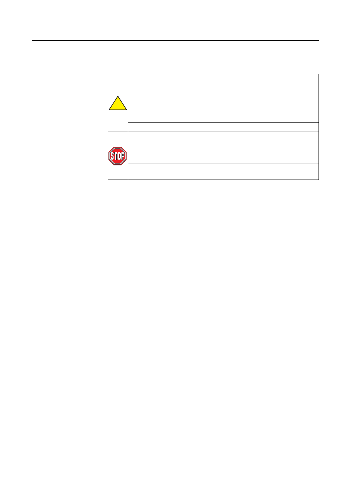
2. Safety information .....................................................................7
3. Instructions ................................................................................8
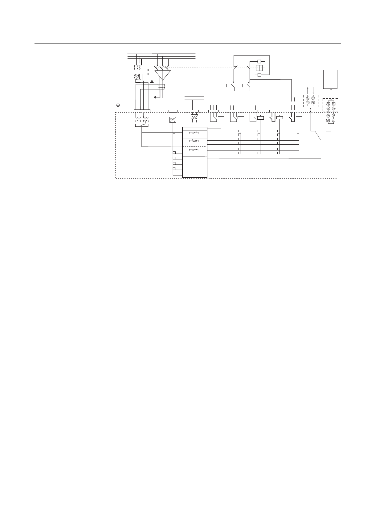
3.1. Application .....................................................................................8
3.2. Requirements ................................................................................8
3.3. Configuration .................................................................................8
4. Technical description .............................................................10
4.1. Functional description .................................................................10
4.1.1. Product functions .............................................................10
4.1.1.1. Schema of product functions ..............................10
4.1.1.2. Earth-fault current, zero-sequence voltage and
intermittent earth-faults ......................................10
4.1.1.3. Inputs .................................................................11
4.1.1.4. Outputs ...............................................................11
4.1.1.5. Circuit-breaker failure protection unit .................11
4.1.1.6. Disturbance recorder ..........................................11
4.1.1.7. HMI module ........................................................11
4.1.1.8. Non-volatile memory ..........................................11
4.1.1.9. Self-supervision ..................................................12
4.1.2. Measurements .................................................................12
4.1.3. Configuration ....................................................................13
4.1.4. Protection .........................................................................13
4.1.4.1. Block diagram ....................................................13
4.1.4.2. Directional or non-directional earth-fault
current unit 14
4.1.4.3. Zero-sequence voltage unit ................................18
4.1.4.4. Protection against intermittent earth-faults .........19
4.1.4.5. Time/current characteristics ...............................20
4.1.4.6. Settings ..............................................................29
4.1.4.7. Technical data on protection functions ..............37
4.1.5. Indicator LEDs and alarm indication messages ...............38
4.1.6. Commissioning test ..........................................................39
4.1.7. Disturbance recorder .......................................................39

4
1MRS 750616-MUM
Directional or Non-Directional Earth-Fault Relay
Technical Reference Manual
REJ 527
4.1.7.1. Function .............................................................39
4.1.7.2. Disturbance recorder data .................................39
4.1.7.3. Control and indication of disturbance recorder
status .................................................................40
4.1.7.4. Triggering ...........................................................41
4.1.7.5. Settings and unloading ......................................41
4.1.7.6. Event code of the disturbance recorder .............41
4.1.8. Recorded data of the last events .....................................41
4.1.9. External serial communication .........................................42
4.1.9.1. Communication ports .........................................42
4.1.9.2. IEC 60870-5-103 remote communication
protocol ..............................................................43
4.1.9.3. Event codes .......................................................48
4.1.9.4. SPA bus communication protocol parameters ...49
4.1.10.Self-supervision (IRF) system ..........................................56
4.1.11.Relay parameterization ....................................................56
4.2. Design description ......................................................................56
4.2.1. Input/output connections .................................................56
4.2.2. Serial communication connections ..................................59
4.2.3. Technical data .................................................................60
5. Ordering information ............................................................. 64
6. References .............................................................................. 65
7. Index ........................................................................................ 66
8. Abbreviations ......................................................................... 69
9. Check lists ......................................................................... 70
10.Customer feedback ............................................................... 73

1MRS 750616-MUM Directional or Non-Directional Earth-Fault Relay
Technical Reference Manual
REJ 527
5
1. Introduction
1.1. About this manual
The purpose of this manual is to provide the user with thorough information on the
protection relay REJ 527 and its applications, focusing on giving a technical
description of the relay.
Refer to the Operator’s Manual for instructions on how to use the
Human-Machine Interface (HMI) of the relay, also known as the Man-Machine
Interface (MMI), and to the Installation Manual for installation of the relay.
1.2. The use of the relay
The directional or non-directional earth-fault relay REJ 527 is intended for
earth-fault protection in medium voltage distribution networks but can also be used
for protection of generators, motors and transformers.
The REJ 527 is based on a microprocessor environment. A self-supervision system
continuously monitors the operation of the relay.
The HMI includes a Liquid Crystal Display (LCD) which makes the local use of the
relay safe and easy.
Localcontrolof therelayvia serialcommunicationcan becarriedoutwithaportable
computer connected to thefront connector and remote control via the rear connector
connected to the distribution automation system through the serial interface and the
fibre-optic bus.
1.3. Features
• Directional or non-directional low-set earth-fault current stage with
definite-time or inverse definite minimum time (IDMT) characteristic
• Directional or non-directional high-set earth-fault current stage with definite-time
characteristic
• Deblocking zero-sequence voltage stage with definite-time characteristic
• The two earth-fault current stages can be configured to operate alternatively as
two voltage stages: three-stage voltage monitoring operation possible
• Intermittent earth-fault protection
• Circuit-breaker failure protection (CBFP)
• Disturbance recorder
• recording time up to 19 seconds
• triggering by a start or a trip signal from any protection stage and/or by a binary
input signal
• records two analogue channels and seven digital channels
• adjustable sampling rate
• Non-volatile memory for
• up to 60 event codes
• setting values

6
1MRS 750616-MUM
Directional or Non-Directional Earth-Fault Relay
Technical Reference Manual
REJ 527
• disturbance recorder data
• recorded data of the five last events with time stamp
• number of starts for each stage
• alarm indication messages and LEDs showing the status at the moment of
power failure
• Two accurate measuring inputs
• Galvanically isolated binary input with a wide input voltage range
• All settings can be modified with a personal computer
• HMI with an alphanumeric LCD and manoeuvring buttons
• IEC 60870-5-103 and SPA bus communication protocols
• Two normally open power output contacts
• Two change-over signal output contacts
• Output contact functions freely configurable for desired operation
• Optical PC-connector for two-way data communication (front)
• RS-485 connector (rear) for system communication
• Continuous self-supervision of electronics and software. At an internal relay
fault (IRF), all protection stages and outputs are blocked.
• User-selectable rated frequency 50/60 Hz
• User-selectable password protection for the HMI
• Display of primary current and voltage values as well as phase angle values
• Multi-language support
1.4. Guarantee
Please inquire the guarantee of your nearest ABB representative.

1MRS 750616-MUM Directional or Non-Directional Earth-Fault Relay
Technical Reference Manual
REJ 527
7
2. Safety information
Dangerous voltages can occur on the connectors, even though the
auxiliary voltage has been disconnected
National and local electrical safety regulations must always be
followed
The device contains components which are sensitive to electrostatic
discharge
The frame of the device has to be carefully earthed
Only a competent electrician is allowed to carry out the electrical
installation
Non-observance can result in death, personal injury or substantial
property damage
Breaking the sealing tape on the rear panel of the device will result in
loss of warranty and proper operation will no longer be guaranteed
!

8
1MRS 750616-MUM
Directional or Non-Directional Earth-Fault Relay
Technical Reference Manual
REJ 527
3. Instructions
3.1. Application
The directional or non-directional earth-fault relay REJ 527 is a secondary relay
which is connected to the voltage and current transformers of the object to be
protected. The earth-fault current and the zero-sequence voltage unit continuously
measurethe zero-sequencevoltage, earth-fault current andphase angleof the object.
On detection of a fault, the relay will start, trip the circuit breaker, provide alarms,
record fault data, etc., in accordance with the application and the configured relay
functions.
The voltage unit includes low-set stage U0b> and the earth-fault current unit low-set
stage I0> and high-set stage I0>>. The earth-fault stages can be replaced by two
additional voltage stages, low-set stage U0> and high-set stage U0>>.
The protection functions are independent of each other and have their own setting
groups and data recordings. The voltage and current functions use conventional
transformer measurement.
An output contact matrix allows start or trip signals from the protection stages to be
routed to the desired output contact.
3.2. Requirements
When the REJ 527 is operating under the conditions specified below (see also
“Technical data”), it will be practically maintenance-free. The relay includes no
parts or components subject to abnormal physical or electrical wear under normal
operating conditions.
Environmental conditions
3.3. Configuration
Setting and connection example
The appropriate configuration of the output contact matrix enables the use of the
signals from the earth-fault current and the voltage unit as contact functions. The
start signals can be used for blocking co-operating protection relays, signalling and
initiating autoreclosing.
Figure 3.3.-1 represents the REJ 527 with the default configuration: all trips are
routed to trip the circuit breaker.
• Specified ambient service temperature range -10...+55°C
• Temperature influence on the operation accuracy of the
protection relay within the specified ambient service
temperature range
0.1% / °C
• Transport and storage temperature range -40...+70°C

1MRS 750616-MUM Directional or Non-Directional Earth-Fault Relay
Technical Reference Manual
REJ 527
9
)LJ &RQQHFWLRQGLDJUDPRIWKHGLUHFWLRQDOHDUWKIDXOWUHOD\
L1
L2
L3
PC
100V
~
~
PO1
IO
PO2
++
IRF
+
+
-
-
++
BI
0
I
IRF
+ -
Uaux
START
TRIP
START
TRIP
1
2
3
SGB1
SGB1
SGB1
Io>>
SGR1
SGR2
SGR3
SGR4
X
3
X
3
2
X
2
X
1
X
1
X
X
4
X
4
X
4
X
3
2
X
1
X
SGR5
SGR6
START
TRIP
5 6 3 4
13 14 15
1 2
17 18
1 2 3 4 6
SGB1
SGB1
SGB1
5
6
7
10 11 12 7 8 9
SO1
X2.1 X2.1 X2.1
SO2
X2.1 X2.1 X2.1 X2.1
X1.1
1MKC950001-1
RER 103
Tx Rx
Io>
Uob>
P1
P2
S2
S1
A
N
da
dn
ConD527
4SGB1
*REJ527B 418BAA: 2 = 5 A
3 = 1 A
REJ527B 411BAA: 2 = 1 A
3 = 0.2 A
*
Blocking of stage Io>>
Blocking of stage Io>
Blocking of stage Uob>
X=Default value
Optical
PC-interface
Spa Bus
I/O
INDICATIONS CLEARED
OUTP. CONT. UNLATCHED
AND INDIC. CLEARED
SWITCHGROUP SELECTION
MEMORIZED VALUES AND
INDIC. CLEARED; OUTPUT
CONTACTS UNLATCHED

10
1MRS 750616-MUM
Directional or Non-Directional Earth-Fault Relay
Technical Reference Manual
REJ 527
4. Technical description
4.1. Functional description
4.1.1. Product functions
4.1.1.1. Schema of product functions
)LJ 3URGXFWIXQFWLRQV
4.1.1.2. Earth-fault current, zero-sequence voltage and intermittent
earth-faults
Refer to sections:
• 4.1.4.2. “Directional or non-directional earth-fault current unit”
• 4.1.4.3. “Zero-sequence voltage unit”
• 4.1.4.4. “Protection against intermittent earth-faults”
50 N
Io
PrF5_7
Uo
51 N
59 N
67 N
62 BF
Earth-fault protection with definite- or
inverse-time characteristic, low-set stage
Earth-fault protection with instantaneous
or definite-time characteristic, high-set
stage
PO1
PO2
SO1
SO2
IRF
Zero-sequence voltage element
Circuit-breaker failure
protection
Remote reset, remote setting control or blocking
input for the different protection stages
Serial communication
Directional earth-fault element
Optical
pc-interface
Binary input BI

1MRS 750616-MUM Directional or Non-Directional Earth-Fault Relay
Technical Reference Manual
REJ 527
11
4.1.1.3. Inputs
TheREJ 527includes twoenergizinginputsandoneexternalbinary inputcontrolled
by an external voltage. For details, refer to section Input/output connections and
tables 4.1.4.6-7, 4.2.1-1and 4.2.1-5.Thefunctionofthebinaryinputis determined
using the SGB switches.
4.1.1.4. Outputs
The REJ 527 is provided with two power outputs (PO1 and PO2) and two signal
outputs (SO1 and SO2). Switchgroups SGR1...6 are used for routing start and trip
signals from the protection stages to the desired signal or power output. PO1 and
PO2 can be configured to be latched and the minimum pulse length to 40 or 80 ms.
4.1.1.5. Circuit-breaker failure protection unit
The REJ 527 features a circuit-breaker failure protection (CBFP) unit. The CBFP
unit will generate a trip signal via output PO2 if the fault has not been cleared on
expiration of the set operate time 0.10 s...1.00 s.
Normally, the CBFP unit controls the upstream circuit breaker. It can also be used
for tripping via redundant trip circuits of the same circuit breaker. The CBFP unit is
activated with a switch of switchgroup SGF1.
4.1.1.6. Disturbance recorder
TheREJ527 includesan internal disturbancerecorderwhich recordsthe momentary
measured values, or the RMS curves of the measured signals, and seven digital
signals: the external binary input signal and the states of the internal protection
stages. The disturbance recorder can be set to be triggered by a start or a trip signal
from any protection stage and/or by an external binary input signal,and either on the
falling or rising triggering edge.
4.1.1.7. HMI module
The HMI of the REJ 527 is equipped with six push-buttons and an alphanumeric
2x16 characters’ LCD. The push-buttons are used for navigating in the menu
structure and for adjusting set values.
An HMI password can be set to protect all user-changeable values from being
changed by an unauthorised person. The HMI password will remain inactive and
will thus not be required for altering parameter values until the default HMI
password has been replaced. Entering the HMI password successfully can be
selected to generate an event code. This feature can be used to indicate interaction
activities via the local HMI. For further information on the HMI, refer to the
Operator’s Manual.
4.1.1.8. Non-volatile memory
The REJ 527 can be configured to store various data in the non-volatile memory,
which will retain its data also in case of loss of auxiliary voltage. Alarm indication
messagesandLEDs,thenumberofstarts,disturbancerecorderdata,eventcodesand
recorded data can all be configured to be stored in the non-volatile memory whereas
setting values will always be stored.

12
1MRS 750616-MUM
Directional or Non-Directional Earth-Fault Relay
Technical Reference Manual
REJ 527
4.1.1.9. Self-supervision
The self-supervision system of the REJ 527 manages run-time fault situations and
informs the user about an existing fault. When the self-supervision system detects a
permanent internal relay fault, the READY indicator LED will start to blink. At the
same time the self-supervision alarm relay (also referred to as the IRF relay), which
is normally picked up, will drop off and a fault code will appear on the LCD. The
fault code is numerical and identifies the fault type. For fault codes, refer to section
Internal fault in the Operator’s Manual.
)LJ ,QWHUQDOIDXOW
Fault codes can indicate:
• no response on the output contact test
• faulty program, work or parameter memory
• internal reference voltage error
4.1.2. Measurements
The table below presents the measured values which can be accessed through the
HMI. The measured voltage is shown as a percentage of the rated voltage, Un, and
the measured currents of the rated current, In, of the energizing input. The phase
angle is shown in degrees and can be selected to be shown either as the angle
between the voltage and the current or as the angle between the basic angle and the
currentwith switch SGF3/8. If the measured currentand voltage values are too low,
i.e. lower than 0.50 percent, dashes will be shown on the LCD.
Faultc
C
E
STARTREADY TRIP
INTERNAL FAULT
FAULT CODE :56
Table 4.1.2-1 Measured values
Indicator Measured data
U0Zero-sequence voltage
I0Earth-fault current
IϕDirectional earth-fault current
ϕPhase angle

1MRS 750616-MUM Directional or Non-Directional Earth-Fault Relay
Technical Reference Manual
REJ 527
13
4.1.3. Configuration
The figure below illustrates how the start, trip and binary input signals can be
configured to obtain the required protection functionality.
)LJ 6LJQDOGLDJUDPRIWKHGLUHFWLRQDOHDUWKIDXOWUHOD\
The functions of the blocking and start signals are selected with the switches of
switchgroups SGF, SGB and SGR. The checksums of the switchgroups are found
under“SETTINGS”intheHMI menu. Thefunctionsoftheseswitchesareexplained
in detail in the corresponding SG_ -tables.
4.1.4. Protection
4.1.4.1. Block diagram
)LJ %ORFNGLDJUDPRIWKHGLUHFWLRQDOHDUWKIDXOWUHOD\5(-
+ ++
IRF
1
2
3
SGB1
SGB1
SGB1
Io>>
SGR1
SGR2
SGR3
SGR4
3
3
3
3
2
2
2
2
1
1
1
1
4
4
4
4
4
4
3
3
2
2
1
1
SGR5
SGR6
5 6 3 4
13 14 15
17 18
SGB1
SGB1
SGB1
5
6
7
10 11 12 7 8 9
X2.1
Io>
Uob>
SGF1...SGF5
Uo
Io
BI IRF SO2 SO1 PO2 PO1
SGB1
4
START
TRIP
START
TRIP
START
TRIP
Blocking of stage Io>>
Blocking of stage Io>
Blocking of stage Uob>
INDICATIONS CLEARED
OUTP. CONT. UNLATCHED
AND INDICATIONS CLEARED
MEMORIZED VALUES AND
INDIC.CLEARED; OUTPUT
CONTACTS UNLATCHED
SWITCHGROUP SELECTION
SGF1/5
1
1
C
to>>
1
C
START
TRIP
Uob>
Io>
Io>>
tb>
to>
SGR2/x
SGR1/x
SGR5/x
SGR6/x
SGR4/x
SGR3/x
tb>
70 ms
to>,k
70 ms
to>>
60 ms
0.12 * Io>
1.5 * Io>
1.25 * Io>
2 * Io>>
SGF2/1
Io>>
60 ms
SGB1/1
SGB1/2
SGB1/3
SGB1/5
SGB1/6
SGB1/7
SGF2/3
SGF2/7
SGF3/1
SGF3/3
SGF2/8
SGB1/4
SGB1/8
Uob
Io
BI
Uob>
Uo>
Io>
Uo>>
Block5_7
&
&
&
0.50% x Un
0.48% x In jb/Ij
j
0.1 ... 1s
SGF1/1
C5 s
PO1
1
SO1
SO2
4
3
21
1
C
5 s
PO2
SGF1/2
&
CLEAR INDICATIONS AND MEMORIZED VALUES
CLEAR INDICATIONS AND MEMORIZED VALUES; UNLATCH OUTPUT CONTACTS
CLEAR INDICATIONS
SETTINGS (Group 1/Group 2)
BASIC ANGLE CONTROL or Ijcharacteristic (sin(j) or cos(j))

14
1MRS 750616-MUM
Directional or Non-Directional Earth-Fault Relay
Technical Reference Manual
REJ 527
4.1.4.2. Directional or non-directional earth-fault current unit
The high-set and the low-set stage of the directional earth-fault current unit can be
configured to be either directional or non-directional. The directional
earth-fault stages can be given either a basic angle or a sin(ϕ) or a cos(ϕ)
characteristic.
The start and the tripping of the directional earth-fault stages with the basic angle
characteristic are based on measuring the earth-fault current, I0, the zero-sequence
voltage, U0,and the phase angle, ϕ, between the voltage and the current. An
earth-fault stage will start when the following three criteria are fulfilled at the same
time:
• The earth-fault current, I0,exceeds the set start value of the low- or high-set
earth-fault stage.
• The zero-sequence voltage, U0,exceeds the set start value of U0b>, which is the
same for both stages in the deblocking mode.
• The phase angle, ϕ, between the voltage and the current falls within the operation
sector ϕb±∆ϕ.
The basic angle of the network is -90°for isolated neutral networks and 0°for
resonant earthed networks, earthed with an arc suppression coil (Petersen coil) with
or without a parallel resistor. The operation sector is selectable and can be either
∆ϕ=±80°or ±88°. Both operation sectors can be extended.
When an earth-fault stage starts, a startsignal will begenerated and a start indication
shown on the HMI. If the above mentioned criteria remain fulfilled until the set
operate time elapses, the stage will deliver a trip signal and a trip indication will be
shown on the HMI. The trip indication will remain active although the protection
stage is reset. The direction of the fault spot is determined by means of the angle
between the voltage and the current. Basic angle ϕbcan be set between -90°and 0°.
When basic angle ϕbis 0-°, the negative quadrant of the operation sector can be
extended with ϕa(see Fig. 4.1.4.2.-1). Extended operation sector ϕacan be set
between 0 and 90°.
Figures 4.1.4.2.-1, 4.1.4.2.-2 and 4.1.4.2.-3 show examples of the basic angle
characteristic.

1MRS 750616-MUM Directional or Non-Directional Earth-Fault Relay
Technical Reference Manual
REJ 527
15
)LJ 2SHUDWLRQFKDUDFWHULVWLFRIWKHGLUHFWLRQDOHDUWKIDXOWSURWHFWLRQ
XQLWZKHQEDVLFDQJOHϕ
E
°RSHUDWLRQVHFWRU∆ϕ ±DQG
H[WHQGHGRSHUDWLRQVHFWRUϕ
D
)LJ 2SHUDWLRQFKDUDFWHULVWLFZKHQEDVLFDQJOHϕ
E
°RSHUDWLRQ
VHFWRU∆ϕ ±DQGH[WHQGHGRSHUDWLRQVHFWRUϕ
D
OPERATION
AREA
Io>
OPERATION
AREA
5
-80° -60° -40° -20° 0° 20° 40° 60° 80° 100°-100°
1
2
3
4
6
NON-OPERATION AREA
ϕb=0°
∆ϕ=80°
Io
In
-120°-140°
ϕa=40°
Ba_0_deg
Negative
quadrant
Positive
quadrant
OPERATION SECTOR
ϕb=0°
∆ϕ=80°
Uo
Io
ϕ
∆ϕ
Io>
LEAD LAG
ϕa=40°
Ba_0_degrees

16
1MRS 750616-MUM
Directional or Non-Directional Earth-Fault Relay
Technical Reference Manual
REJ 527
)LJ 2SHUDWLRQFKDUDFWHULVWLFZKHQEDVLFDQJOHϕ
E
°
The start and the tripping of the directional earth-fault stages with the sin(ϕ) or the
cos(ϕ) characteristic are based on measuring the earth-fault current, I0,the zero-
sequence voltage, U0,and the phase angle, ϕ, between the voltage and the current.
The sinus or cosinus value of the phase angle is calculated and multiplied by the
earth-fault current to get the directional earth-fault current, Iϕ. An earth-fault stage
will start when the following three criteria are fulfilled at the same time:
• The directional earth-fault current, Iϕ, exceeds the set start value of the
low- or high-set earth-fault stage.
• The zero-sequence voltage, U0,exceeds the set start value of U0b>, which is the
same for both stages in the deblocking mode.
• The phase angle, ϕ, between the voltage and the current falls within the operation
sector, corrected with ϕc.
When an earth-fault stage starts, a startsignal will begenerated and a start indication
shown on the HMI. If the above mentioned criteria remain fulfilled until the set
operate time elapses, the stage will deliver a trip signal and a trip indication will be
shown on the HMI. The trip indication will remain active although the protection
stage is reset. The direction of the fault spot is determined by means of the angle
between the voltage and the current. Directional earth-fault characteristic sin(ϕ)
corresponds to the earth-fault protection with the basic angle -90° and cos(ϕ) to the
earth-fault protection with the basic angle 0°.
Figures 4.1.4.2.-4 and 4.1.4.2.-5 show examples of the sin(ϕ) and the cos(ϕ)
characteristics.
Uo
Io
ϕ
∆ϕ
OPERATION SECTOR
ϕb=-90°
∆ϕ=80°
Io>
LEAD LAG
Ba_-90_degrees

1MRS 750616-MUM Directional or Non-Directional Earth-Fault Relay
Technical Reference Manual
REJ 527
17
)LJ 2SHUDWLRQFKDUDFWHULVWLFVLQϕ
)LJ 2SHUDWLRQFKDUDFWHULVWLFFRVϕ
The operation directions, forward or reverse, of the directional earth-fault stages can
be selected independently of each other. The directional stages can also be
separately configured to be non-directional.
When the earth-fault current exceeds the set start value of low-set stage I0>, the
earth-fault unit will start to deliver a start signal after a ~ 70 ms’ start time. When
the set operate time at definite-time characteristic or the calculated operate time at
IDMT characteristic elapses, the earth-fault unit will deliver a trip signal.
ϕ
Io
Uo
Io>(>)
ϕc=2..7°
ϕc=2..7°
Sin_fi_char
ϕ
Io
Uo
Io>(>)
ϕc=2..7°ϕc=2..7°
Cos_fi_char

18
1MRS 750616-MUM
Directional or Non-Directional Earth-Fault Relay
Technical Reference Manual
REJ 527
When the earth-fault current exceeds the set start value of high-set stage I0>>, the
earth-fault unit will start to deliver a start signal after a ~ 60 ms’ start time. When
the set operate time elapses, the earth-fault unit will deliver a trip signal.
It is possible to block the start and thetripping of an earth-faultstage by applying an
external binary input signal to the relay.
The inverse-time function of stage I0> can be set to be inhibited when stage I0>>
starts with a switch of switchgroup SGF2. In this case the operate time will be
determined by stage I0>>.
The high-set stage can be set out of operation. This state will be indicated by dashes
on the LCD and by “999” when the set start value is read via serial communication.
The set start value of stage I0>> can be automatically doubled in a start situation,
e.g. when the object to be protected is connected to a distribution network. Thus a
set start value below the connection inrush current level can be selected for stage
I0>>. A start situation is defined as a situation where the earth-fault current rises
from a value below 12% x I0> to a value above 150% x I0> in less than 60 ms. The
start situation ends when the current falls below 125% x I0>.
4.1.4.3. Zero-sequence voltage unit
When the zero-sequence voltage exceeds the set start value of low-set stage U0b>,
the voltage unit will start to deliver a start signal after a ~ 70 ms’ start time. When
the set operate time at definite-time characteristic elapses, the voltage unit will
deliver a trip signal.
The two current stages, I0> and I0>>, can be replaced by two additional voltage
stages, low-set stage U0> and high-set stage U0>>, to create a three-stage zero-
sequencevoltage module. Allthree voltage stages measure the same voltage but can
have separate settings both regarding sensitivity and operate time. The signalling
and trip relays can also be selected separately for all three stages.
When the zero-sequence voltage exceeds theset start value of low-set stage U0>, the
voltage unit will start to deliver a start signal after a ~ 70 ms’ start time. When the
set operate time at definite-time characteristic elapses, the voltage unit will deliver
a trip signal.
When the zero-sequence voltage exceeds the set start value of high-set stage U0>>,
the voltage unit will start to deliver a start signal after a ~ 60 ms’ start time. When
the set operate time elapses, the voltage unit will deliver a trip signal.
It is possible to block the start and the tripping of a voltage stage by applying an
external binary input signal to the relay.
High-set stage U0>> can be set out of operation. This state will be indicated by
dashes on the LCD and by “999” when the set start value is read via serial
communication.

1MRS 750616-MUM Directional or Non-Directional Earth-Fault Relay
Technical Reference Manual
REJ 527
19
4.1.4.4. Protection against intermittent earth-faults
An intermittent earth-fault typically occurs in an insulated cable where the
insulation has a crack and water leaks into the cable. The earth-fault dries up the
crack in the cable, extinguishing the fault, but reappears after a short time as water
leaks back through the crack. The process repeats, resulting in a succession of fault
current pulses.
)LJ ,QWHUPLWWHQWIDXOW
When the resetting time of the overcurrent unit is shorter than the interval between
the fault current pulses, the relay will be continually reset and not able to trip. A
resetting time longer than the start time, but short enough not to interfere with
normal operation of the protection and control system, will help to eliminate some
less common health and safety problems.
)LJ 6HOHFWDEOHUHVHWWLQJWLPH
Momentary peak
value of neutral
current Io
Momentary
value of
neutral
voltage Uo
Fundamental
amplitude of Io
Interm2
Set value
Trip level
≥100ms ≥100ms
Resettime

20
1MRS 750616-MUM
Directional or Non-Directional Earth-Fault Relay
Technical Reference Manual
REJ 527
The resetting time can be set to 80, 100, 500 or 1000 ms in SGF5. When the resetting
time is set to 100 ms or above, earth-fault stage I0> will operate as an intermittent
earth-fault stage.
1RWH
If the CBFP function is in use and a resetting time longer than 80 ms is selected, a
CBFP operate time longer than the resetting time is recommended.
4.1.4.5. Time/current characteristics
The low-set earth-fault current stage can be given either a definite-time or an inverse
definite minimum time (IDMT) characteristic whereas the high-set earth-fault
current stage and the voltage stage(s) feature the definite-time characteristic alone.
The settings of switches SGF4/1...6 determine the operation mode of the stage.
Refer to section Settings for additional information.
At IDMT characteristic, the operate time of the stage is dependent on the current
value: the higher the current value, the shorter the operate time. Six time/current
curve groups are available, of which four comply with the IEC 60255 standard: the
normal inverse, very inverse, extremely inverse and long-time inverse. The two
additional inverse-time curve groups, referred to as RI and RD, are special curve
groups according to ABB praxis.
Characteristics according to the IEC 60255 standard
The relay module incorporates four internationally standardized time/current curve
groupscalledextremelyinverse,very inverse,normalinverseand long-timeinverse.
The relationship between time and current is in accordance with the IEC 60255-3
standard and can be expressed as follows:
where
t = operate time
k = time multiplier
I0= earth-fault current value
I0> = set start value
Table 4.1.4.5-1 The values of constants
α
and
β
Time/current curve group αβ
Normal inverse 0.02 0.14
Very inverse 1.0 13.5
Extremely inverse 2.0 80.0
Long-time inverse 1.0 120
ts[] kβ×
Io
Io>
---------
α
1–
--------------------------=
Other manuals for REJ 527
3
Table of contents
Other ABB Relay manuals