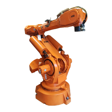
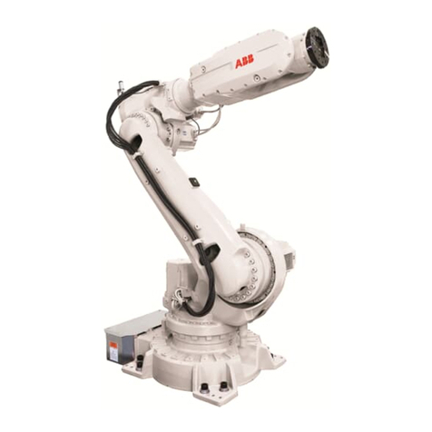
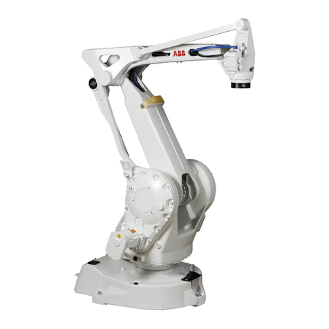
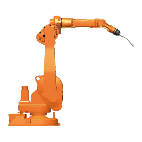
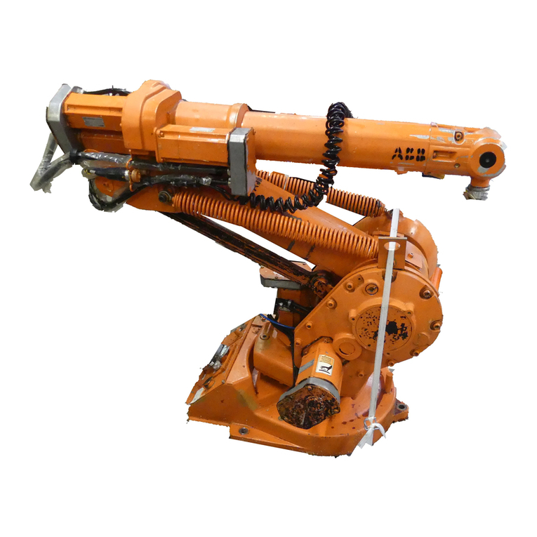
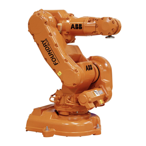
ABB IRB 660 User manual

ROBOTICS
Product manual
IRB 660

Trace back information:
Workspace 20C version a3
Checked in 2020-09-14
Skribenta version 5.3.075

Product manual
IRB 660 - 180/3.15
IRB 660 - 250/3.15
IRC5
Document ID: 3HAC025755-001
Revision: W
© Copyright 2006-2020 ABB. All rights reserved.
Specifications subject to change without notice.

The information in this manual is subject to change without notice and should not
be construed as a commitment by ABB. ABB assumes no responsibility for any errors
that may appear in this manual.
Except as may be expressly stated anywhere in this manual, nothing herein shall be
construed as any kind of guarantee or warranty by ABB for losses, damage to persons
or property, fitness for a specific purpose or the like.
In no event shall ABB be liable for incidental or consequential damages arising from
use of this manual and products described herein.
This manual and parts thereof must not be reproduced or copied without ABB's
written permission.
Keep for future reference.
Additional copies of this manual may be obtained from ABB.
Original instructions.
© Copyright 2006-2020 ABB. All rights reserved.
Specifications subject to change without notice.

Table of contents
9Overview of this manual ...................................................................................................................
16Product documentation ....................................................................................................................
18How to read the product manual ......................................................................................................
191 Safety
191.1 Safety information .............................................................................................
191.1.1 Limitation of liability .................................................................................
201.1.2 Requirements on personnel ......................................................................
211.2 Safety signals and symbols .................................................................................
211.2.1 Safety signals in the manual ......................................................................
231.2.2 Safety symbols on manipulator labels .........................................................
291.3 Robot stopping functions ....................................................................................
301.4 Installation and commissioning ............................................................................
331.5 Operation ........................................................................................................
331.5.1 Unexpected movement of robot arm ...........................................................
341.6 Maintenance and repair ......................................................................................
341.6.1 Maintenance and repair ............................................................................
371.6.2 Emergency release of the robot axes ..........................................................
381.6.3 Brake testing ..........................................................................................
391.7 Troubleshooting ................................................................................................
401.8 Decommissioning ..............................................................................................
412 Installation and commissioning
412.1 Introduction to installation and commissioning .......................................................
422.2 Unpacking .......................................................................................................
422.2.1 Pre-installation procedure .........................................................................
462.2.2 Working range and type of motion ..............................................................
482.2.3 Risk of tipping/stability .............................................................................
492.2.4 The unit is sensitive to ESD .......................................................................
502.3 On-site installation ............................................................................................
502.3.1 Lifting robot with fork lift ...........................................................................
552.3.2 Lifting robot with roundslings ....................................................................
582.3.3 Lifting robot with lifting slings ....................................................................
602.3.4 Manually releasing the brakes ...................................................................
622.3.5 Lifting the base plate ................................................................................
632.3.6 Securing the base plate ............................................................................
682.3.7 Orienting and securing the robot ................................................................
712.3.8 Fitting equipment on robot .......................................................................
752.3.9 Signal lamp (option) .................................................................................
762.3.10 Loads fitted to the robot, stopping time and braking distances .........................
772.4 Restricting the working range ..............................................................................
772.4.1 Axes with restricted working range .............................................................
782.4.2 Mechanically restricting the working range of axis 1 ......................................
802.4.3 Extended working range, axis 1 (option 561-1) .............................................
812.4.4 Installation of position switch, axis 1 (option) ................................................
872.5 Robot in cold environments .................................................................................
872.5.1 Start of robot in cold environments ............................................................
882.6 Electrical connections ........................................................................................
882.6.1 Robot cabling and connection points ..........................................................
913 Maintenance
913.1 Introduction ......................................................................................................
923.2 Maintenance schedule and expected component life ...............................................
923.2.1 Specification of maintenance intervals ........................................................
933.2.2 Maintenance schedule .............................................................................
953.2.3 Expected component life .........................................................................
Product manual - IRB 660 5
3HAC025755-001 Revision: W
© Copyright 2006-2020 ABB. All rights reserved.
Table of contents

963.3 Inspection activities ...........................................................................................
963.3.1 Inspecting the oil level in axis-1 gearbox .....................................................
983.3.2 Inspecting, oil level gearbox axes 2 - 3 .......................................................
1013.3.3 Inspecting, oil level gearbox axis 6 ............................................................
1033.3.4 Inspecting, balancing device bearings and piston rod guide ring ......................
1073.3.5 Inspecting, cable harness ........................................................................
1103.3.6 Inspecting the information labels ................................................................
1123.3.7 Inspecting the axis-1 mechanical stop pin ...................................................
1143.3.8 Inspecting the additional mechanical stops .................................................
1163.3.9 Inspection, dampers ................................................................................
1183.3.10 Inspection, position switch axis 1 ...............................................................
1203.3.11 Inspecting the signal lamp (option) .............................................................
1223.4 Replacement/changing activities ..........................................................................
1223.4.1 Type of lubrication in gearboxes ................................................................
1233.4.2 Changing oil, axis-1 gearbox .....................................................................
1263.4.3 Changing oil, gearbox axes 2 and 3 ...........................................................
1303.4.4 Changing oil, gearbox axis 6 .....................................................................
1323.4.5 Replacing the SMB battery ........................................................................
1363.5 Lubrication activities ..........................................................................................
1363.5.1 Lubricating balancing device bearings and piston rod ....................................
1393.6 Cleaning activities .............................................................................................
1393.6.1 Cleaning the IRB 660 ...............................................................................
1414 Repair
1414.1 Introduction ......................................................................................................
1424.2 General procedures ...........................................................................................
1424.2.1 Performing a leak-down test ......................................................................
1434.2.2 Mounting instructions for bearings .............................................................
1454.2.3 Mounting instructions for sealings ..............................................................
1484.2.4 Cut the paint or surface on the robot before replacing parts ............................
1494.2.5 The brake release buttons may be jammed after service work .........................
1504.3 Complete robot .................................................................................................
1504.3.1 Replacing cable harness, lower end (axes 1-3) .............................................
1584.3.2 Replacing the cable harness, upper end (incl. axis 6) .....................................
1644.3.3 Replacing the base, including axis 1 gearbox ...............................................
1724.4 Upper and lower arm .........................................................................................
1724.4.1 Replacing the turning disk ........................................................................
1764.4.2 Replacement of tilthouse unit ....................................................................
1914.4.3 Replacement of upper arm ........................................................................
2014.4.4 Replacement of linkage - upper rod ............................................................
2054.4.5 Replacing the linkage - lower rod ...............................................................
2094.4.6 Replacement of linkage - link .....................................................................
2164.4.7 Replacing the parallel rod .........................................................................
2214.4.8 Replacing the complete lower arm ..............................................................
2294.4.9 Replacement of parallel arm ......................................................................
2364.5 Frame and base ................................................................................................
2364.5.1 Replacing the balancing device ..................................................................
2444.5.2 Replacing the SMB unit ............................................................................
2474.5.3 Replacing the brake release board .............................................................
2514.6 Motors ............................................................................................................
2514.6.1 Replacing motor, axis 1 ............................................................................
2584.6.2 Replacing motors, axes 2 and 3 .................................................................
2694.6.3 Replacing motor, axis 6 ............................................................................
2764.7 Gearboxes .......................................................................................................
2764.7.1 Replacing the axis 1 gearbox .....................................................................
2874.7.2 Replacing the gearbox, axes 2- 3 ...............................................................
2994.7.3 Replacing gearbox axis 6 ..........................................................................
6 Product manual - IRB 660
3HAC025755-001 Revision: W
© Copyright 2006-2020 ABB. All rights reserved.
Table of contents

3055 Calibration
3055.1 Introduction to calibration ...................................................................................
3055.1.1 Introduction and calibration terminology ......................................................
3065.1.2 Calibration methods .................................................................................
3085.1.3 When to calibrate ...................................................................................
3095.2 Synchronization marks and axis movement directions .............................................
3095.2.1 Synchronization marks and synchronization position for axes .........................
3105.2.2 Calibration movement directions for all axes ................................................
3115.3 Updating revolution counters ...............................................................................
3155.4 Calibrating with Axis Calibration method ...............................................................
3155.4.1 Description of Axis Calibration ..................................................................
3185.4.2 Calibration tools for Axis Calibration ...........................................................
3205.4.3 Installation locations for the calibration tools ...............................................
3225.4.4 Axis Calibration - Running the calibration procedure ......................................
3275.4.5 Reference calibration ...............................................................................
3295.5 Calibrating with Calibration Pendulum method .......................................................
3305.6 Verifying the calibration ......................................................................................
3315.7 Checking the synchronization position ..................................................................
3336 Decommissioning
3336.1 Environmental information ..................................................................................
3356.2 Scrapping of robot .............................................................................................
3366.3 Decommissioning of balancing device ...................................................................
3397 Reference information
3397.1 Introduction ......................................................................................................
3407.2 Applicable standards .........................................................................................
3427.3 Unit conversion .................................................................................................
3437.4 Screw joints ....................................................................................................
3467.5 Weight specifications .........................................................................................
3477.6 Standard tools ..................................................................................................
3487.7 Special tools ....................................................................................................
3517.8 Lifting accessories and lifting instructions ..............................................................
3538 Spare part lists
3538.1 Spare part lists and illustrations ...........................................................................
3559 Circuit diagrams
3559.1 Circuit diagrams ................................................................................................
357Index
Product manual - IRB 660 7
3HAC025755-001 Revision: W
© Copyright 2006-2020 ABB. All rights reserved.
Table of contents

This page is intentionally left blank

Overview of this manual
About this manual
This manual contains instructions for:
• mechanical and electrical installation of the robot
• maintenance of the robot
• mechanical and electrical repair of the robot.
The manual also contains reference information for all procedures detailed in the
manual.
Usage
This manual should be used during:
• installation, from lifting the robot to its work site and securing it to the
foundation, to making it ready for operation
• maintenance work
• repair work.
Who should read this manual?
This manual is intended for:
• installation personnel
• maintenance personnel
• repair personnel.
Prerequisites
Maintenance/repair/installation personnel working with an ABB Robot must:
• be trained by ABB and have the required knowledge of mechanical and
electrical installation/repair/maintenance work.
Product manual scope
The manual covers covers all variants and designs of the IRB 660. Some variants
and designs may have been removed from the business offer and are no longer
available for purchase.
Organization of chapters
The manual is organized in the following chapters:
ContentsChapter
Safety information that must be read through before performing
any installation or service work on robot. Contains general safety
aspects as well as more specific information about how to avoid
personal injuries and damage to the product.
Safety
Required information about lifting and installation of the robot.Installation and commis-
sioning
Step-by-step procedures that describe how to perform mainten-
ance of the robot. Based on a maintenance schedule that may
be used in the work of planning periodical maintenance.
Maintenance
Continues on next page
Product manual - IRB 660 9
3HAC025755-001 Revision: W
© Copyright 2006-2020 ABB. All rights reserved.
Overview of this manual

ContentsChapter
Step-by-step procedures that describe how to perform repair
activities of the robot. Based on available spare parts.
Repair
Calibration procedures and general information about calibra-
tion.
Calibration
Environmental information about the robot and its components.Decommissioning
Useful information when performing installation, maintenance
or repair work. Includes lists of necessary tools, additional
documents, safety standards etc.
Reference information
Complete spare part list of the robot components, shown in
exploded views.
Spare part / part list
Detailed illustrations of the robot with reference numbers to the
part list.
Exploded views
Reference to the circuit diagram for the robot.Circuit diagram
References
Document IDDocument name
3HAC023932-001Product specification - IRB 660
3HAC049102-001Product manual, spare parts - IRB 660
3HAC031045-001Safety manual for robot - Manipulator and IRC5 or OmniCore
controller i
3HAC025691-001Circuit diagram - IRB 660
3HAC021313-001Product manual - IRC5
IRC5 with main computer DSQC 639.
3HAC047136-001Product manual - IRC5
IRC5 with main computer DSQC1000.
3HAC050941-001Operating manual - IRC5 with FlexPendant
3HAC16578-1Operating manual - Calibration Pendulum
3HAC050944-001Operating manual - Service Information System
3HAC051016-001Application manual - Additional axes and stand alone controller
3HAC042927-001Technical reference manual - Lubrication in gearboxes
3HAC050948-001Technical reference manual - System parameters
3HAC030421-001Application manual - CalibWare Field
iThis manual contains all safety instructions from the product manuals for the manipulators and the
controllers.
Revisions
DescriptionRevision
First edition-
Detailed illustrations added in some procedures.A
Art. no. on tools added.
Chapter "Replacement of tilthouse unit" has been changed, in order to
make it easier to follow the procedure.
Continues on next page
10 Product manual - IRB 660
3HAC025755-001 Revision: W
© Copyright 2006-2020 ABB. All rights reserved.
Overview of this manual
Continued

DescriptionRevision
Changes made in:
• Prerequisites in section Overview
• Oil change in section Maintenance
This revision also includes the following additions and/or changes:
• The section "Type of oil in gearboxes" in chapter Maintenance has
been updated according to changes made in oil types and intervals
for oil change.
•Section "Replacement of Cable harness lower end" in chapter Repair
has been updated.
• Section "Replacement of Parallel rod" in chapter Repair has been
updated.
• Section "Replacement of Balancing device" in chapter Repair has
been updated.
• Section "Replacement of Gearbox axis 6" in chapter Repair has
been updated.
• Values for tightening torque on M24 screws in chapter Reference
information, added.
• New revision on Circuit diagrams.
B
This revision includes the following addtions and/or changes:
• Section "Securing the robot" in Installation chapter has been re-
moved. Content is not applicable to IRB 660.
• Section What is an emergency stop? added to chapter Safety
• Section Maintenance schedule in chapter Maintenance: Intervals
for inspection activities and oilchanges have been revised
• Section Maintenance schedule in chapter Maintenance: Overhaul
of robot is new
•Section Maintenance schedule in chapter Maintenance: The inform-
ation about Service Information System (SIS) has been updated
• Section Maintenance schedule in chapter Maintenance: Intervals
for replacement of battery pack changed
• Section Expected lifetime in chapter Maintenance: The lifetime of
certain parts has been revised
• Section Cleaning of robot updated
C
This revision includes the following addtions and/or changes:
• Instruction for how to inspect oil level corrected, see Inspecting, oil
level gearbox axis 6 on page 101.
• Circuit diagrams are not included in this document but delivered as
separate files. See Circuit diagrams on page 355.
• List of safety standards updated.
• Decommissioning chapter added.
• The lifetime of certain parts has been updated, see Expected com-
ponent life on page 95.
The chapter Safety updated with:
• Updated safety signal graphics for the levels Danger and Warning,
see Safety signals in the manual on page 21.
• New safety labels on the manipulators, see Safety symbols on ma-
nipulator labels on page 23.
• Revised terminology: robot replaced with manipulator.
D
This revision includes the following updates:
• Maximum deviation changed, see Securing the base plate on
page 63.
E
Continues on next page
Product manual - IRB 660 11
3HAC025755-001 Revision: W
© Copyright 2006-2020 ABB. All rights reserved.
Overview of this manual
Continued

DescriptionRevision
This revision includes following updates:
• Added index words throughout the manual.
• Inspection method of oil level in gearbox, axis 6, is changed, see
Inspecting, oil level gearbox axis 6 on page 101.
• Position numbers in figure corrected, see Location of dampers on
page 116.
•Removed information about lubricating attachment screws, removed
tightening torque and screw dimension for axis 2 and 3 and added
screw dimension for axis 1, see Inspecting the additional mechan-
ical stops on page 114.
• Changed tightening torque of fork lift adapters, from 60 Nm to 270
Nm, see Lifting robot with fork lift on page 52.
• Changed article numbers of robot power cables, see Robot cable,
power on page 88.
• Information about restricting and extending the working range of
axis 1 is now separated, see Mechanically restricting the working
range of axis 1 on page 78 and the new section Extended working
range, axis 1 (option 561-1) on page 80. Also added signal about
option 561-1 in section Inspecting the axis-1 mechanical stop pin
on page 112.
• Added detailed information about how to decommission the balan-
cing device, see Decommissioning of balancing device on page 336.
• Added new safety symbols, see Safety symbols on manipulator la-
bels on page 23.
F
This revision includes the following updates:
• A new block, about general illustrations, added in section How to
read the product manual on page 18.
• Added a KM10 socket to the list of required equipment and the in-
structions when replacing the lower rod, see section Replacing the
linkage - lower rod on page 205. The tool is also added to the list of
Special tools in the Reference chapter.
• Added instructions for securing parallel arm and lower arm to each
other before removing the lower arm, see Replacing the complete
lower arm on page 221.
• Added guide sleeves to hold the axes 2/3 sealing in place when re-
fitting the lower arm, see Replacing the complete lower arm on
page 221.
• Made minor corrections and improvements in the complete instruc-
tion for how to replace the lower arm system, see Replacing the
complete lower arm on page 221.
• Made minor corrections and improvements in the complete instruc-
tion for how to replace the parallel arm, see Replacement of parallel
arm on page 229.
• Made minor corrections and improvements in the complete instruc-
tion for how to replace the axis 1 gearbox, see Replacing the axis
1 gearbox on page 276.
• Some general tightening torques have been changed/added, see
updated values in Screw joints on page 343.
• Added information about batteries.
G
Continues on next page
12 Product manual - IRB 660
3HAC025755-001 Revision: W
© Copyright 2006-2020 ABB. All rights reserved.
Overview of this manual
Continued

DescriptionRevision
This revision includes the following updates:
• The maximum allowed deviation in levelness of the base plate is
changed, see Securing the base plate on page 63.
•Reference to Hilti standard added to the foundation recommendation
for the base plate and class designation for foundation is changed
to European standard C25/C30 (previously Swedish standard
K25/K30), see Securing the base plate on page 63.
• Corrections and improvements are made in the instruction for how
to replace the axis-2 and axis-3 gearbox, see Replacing the gearbox,
axes 2- 3 on page 287.
• All data about type of lubrication in gearboxes is moved from the
manual to a separate lubrication manual, see Type and amount of
oil in gearboxes on page 122.
• Added spare part numbers for the customer connection kits and
the base plate, see Spare parts - option in Product manual, spare
parts - IRB 660.
• A new SMB unit and battery is introduced, with longer battery life-
time.
H
This revision includes the following updates:
• New article number for painted motor added to spare parts, see
Spare parts - frame to lower arm in Product manual, spare
parts - IRB 660.
• Spare part number on item 102, 104 and 107, frame to base
changed. See Spare parts - frame to Base in Product manual, spare
parts - IRB 660.
• Added information about risks when scrapping a decommissioned
robot, see Scrapping of robot on page 335.
•Spare parts and exploded views are not included in this document
but delivered as a separate document. See Product manual, spare
parts - IRB 660.
• Article number for lubrication tool changed, see Lubricating balan-
cing device bearings and piston rod on page 136
J
This revision includes the following updates:
• The maximum allowed deviation in levelness of the base plate and
foundation is changed, see Securing the base plate on page 63.
• Added tightening torque for R1.SMB and 7th axis connector, ses
Replacing cable harness, lower end (axes 1-3) on page 150.
• Minor corrections.
K
This revision includes the following updates:
• Lifting tools updated (guide pin 3HAC7601-086 and guide pin
3HAC7601-087 removed)
• Special tools updated (Pressing, inner ring 3HAC023112-008 re-
moved)
• Illustrations of SMB battery RMU improved.
L
Published in release R16.2. The following updates are done in this revision:
•Drawing of base plate is not available for purchase, faulty information
removed in Securing the base plate on page 63.
• Corrections due to updates in terminology.
• New standard calibration method is introduced (Axis Calibration).
See Calibration on page 305.
• Information about grounding point added. See Robot cabling and
connection points on page 88.
M
Continues on next page
Product manual - IRB 660 13
3HAC025755-001 Revision: W
© Copyright 2006-2020 ABB. All rights reserved.
Overview of this manual
Continued

DescriptionRevision
Published in release R17.2. The following updates are made in this revision:
• Caution about removing metal residues added in sections about
SMB boards.
• Information about minimum resonance frequency added.
• Bending radius for static floor cables added.
• Updated list of applicable standards.
• Added text regarding overhaul in section specification of mainten-
ance intervals.
• Updated the section Start of robot in cold environments on page87.
•Updated information regarding replacement of brake release board.
• Updated information regarding disconnecting and reconnecting
battery cable to serial measurement board.
• Updated information regarding replacing of balancing device.
• Definition of reference calibration clarified.
N
Published in release R18.1. The following updates are made in this revision:
• Information added about fatigue to Axis Calibration tool, see Calib-
ration tools for Axis Calibration on page 318.
• Added sections in General procedures on page 142.
• Safety restructured.
• New spare part number brake release board (was DSQC563).
• Note added to calibration chapter to emphasize the requirement of
equally dressed robot when using previously created reference
calibration values.
• Information about myABB Business Portal added.
P
Published in release R18.2. The following updates are done in this revision:
• Added locating hole position in mounting flange view.
Q
Published in release R18.2. The following updates are done in this revision:
• Updated references.
R
Published in release 19B. The following updates are made in this revision:
• New touch up color Graphite White available. See Cut the paint or
surface on the robot before replacing parts on page 148.
• Tightening torque for oil plug axis 6 changed to 20 Nm.
• New adapter for axis-3 shaft replacement and updated article
number for KM12 socket for axis-3 and axis-2 shaft replacements.
See Replacement of upper arm on page 191.
S
Published in release 19C. The following updates are made in this revision:
• Added information regarding the support rings of the upper arm
housing, see Replacement of upper arm on page 191.
T
Published in release 19D. The following updates are made in this revision:
• Added press tool for installation of support rings in the upper arm
housing, see Replacement of upper arm on page 191.
• Sealing compound Permatex No. 3 replaced by Trans7 from Trans
Clear.
U
Published in release 20A. The following updates are made in this revision:
•Clarified and added information in mounting instructions for rotating
sealings, see Mounting instructions for sealings on page 145.
• Clarified text about position of robot and added table with depend-
encies between axes during Axis Calibration.
• Changed tightening torque for axis-2 and axis-3 shaft, see Replace-
ment of upper arm on page 191 and increased the torque span for
standard torque wrench, see Standard tools on page 347.
V
Continues on next page
14 Product manual - IRB 660
3HAC025755-001 Revision: W
© Copyright 2006-2020 ABB. All rights reserved.
Overview of this manual
Continued

DescriptionRevision
Published in release 20C. The following updates are made in this revision:
• Changed tightening torques on the wrist oil plugs.
• Removed lifting tool for axis-2 and axis-3 gearbox from the special
tools list (lifting method was changed in previous revision).
W
Product manual - IRB 660 15
3HAC025755-001 Revision: W
© Copyright 2006-2020 ABB. All rights reserved.
Overview of this manual
Continued

Product documentation
Categories for user documentation from ABB Robotics
The user documentation from ABB Robotics is divided into a number of categories.
This listing is based on the type of information in the documents, regardless of
whether the products are standard or optional.
All documents can be found via myABB Business Portal, www.myportal.abb.com.
Product manuals
Manipulators, controllers, DressPack/SpotPack, and most other hardware is
delivered with a Product manual that generally contains:
• Safety information.
• Installation and commissioning (descriptions of mechanical installation or
electrical connections).
•Maintenance (descriptions of all required preventive maintenance procedures
including intervals and expected life time of parts).
• Repair (descriptions of all recommended repair procedures including spare
parts).
• Calibration.
• Decommissioning.
•Reference information (safety standards, unit conversions, screw joints, lists
of tools).
• Spare parts list with corresponding figures (or references to separate spare
parts lists).
• References to circuit diagrams.
Technical reference manuals
The technical reference manuals describe reference information for robotics
products, for example lubrication, the RAPID language, and system parameters.
Application manuals
Specific applications (for example software or hardware options) are described in
Application manuals. An application manual can describe one or several
applications.
An application manual generally contains information about:
• The purpose of the application (what it does and when it is useful).
•What is included (for example cables, I/O boards, RAPID instructions, system
parameters, software).
• How to install included or required hardware.
• How to use the application.
• Examples of how to use the application.
Continues on next page
16 Product manual - IRB 660
3HAC025755-001 Revision: W
© Copyright 2006-2020 ABB. All rights reserved.
Product documentation

Operating manuals
The operating manuals describe hands-on handling of the products. The manuals
are aimed at those having first-hand operational contact with the product, that is
production cell operators, programmers, and troubleshooters.
Product manual - IRB 660 17
3HAC025755-001 Revision: W
© Copyright 2006-2020 ABB. All rights reserved.
Product documentation
Continued

How to read the product manual
Reading the procedures
The procedures contain references to figures, tools, material, and so on. The
references are read as described below.
References to figures
The procedures often include references to components or attachment points
located on the manipulator/controller. The components or attachment points are
marked with italic text in the procedures and completed with a reference to the
figure where the current component or attachment point is shown.
The denomination in the procedure for the component or attachment point
corresponds to the denomination in the referenced figure.
The table below shows an example of a reference to a figure from a step in a
procedure.
Note/IllustrationAction
Shown in the figure Location of
gearbox on page xx.
Remove the rear attachment screws, gearbox.8.
References to required equipment
The procedures often include references to equipment (spare parts, tools, etc.)
required for the different actions in the procedure. The equipment is marked with
italic text in the procedures and completed with a reference to the section where
the equipment is listed with further information, that is article number and
dimensions.
The designation in the procedure for the component or attachment point
corresponds to the designation in the referenced list.
The table below shows an example of a reference to a list of required equipment
from a step in a procedure.
Note/IllustrationAction
Art. no. is specified in Required
equipment on page xx.
Fit a new sealing, axis 2 to the gearbox.3.
Safety information
The manual includes a separate safety chapter that must be read through before
proceeding with any service or installation procedures. All procedures also include
specific safety information when dangerous steps are to be performed.
Read more in the chapter Safety on page 19.
Illustrations
The robot is illustrated with general figures that does not take painting or protection
type in consideration.
Likewise, certain work methods or general information that is valid for several robot
models, can be illustrated with illustrations that show a different robot model than
the one that is described in the current manual.
18 Product manual - IRB 660
3HAC025755-001 Revision: W
© Copyright 2006-2020 ABB. All rights reserved.
How to read the product manual

1 Safety
1.1 Safety information
1.1.1 Limitation of liability
Limitation of liability
Any information given in this manual regarding safety must not be construed as a
warranty by ABB that the industrial robot will not cause injury or damage even if
all safety instructions are complied with.
The information does not cover how to design, install and operate a robot system,
nor does it cover all peripheral equipment that can influence the safety of the robot
system.
In particular, liability cannot be accepted if injury or damage has been caused for
any of the following reasons:
• Use of the robot in other ways than intended.
• Incorrect operation or maintenance.
• Operation of the robot when the safety devices are defective, not in their
intended location or in any other way not working.
• When instructions for operation and maintenance are not followed.
• Non-authorized design modifications of the robot.
• Repairs on the robot and its spare parts carried out by in-experienced or
non-qualified personnel.
• Foreign objects.
• Force majeure.
Spare parts and equipment
ABB supplies original spare parts and equipment which have been tested and
approved. The installation and/or use of non-original spare parts and equipment
can negatively affect the safety, function, performance, and structural properties
of the robot. ABB is not liable for damages caused by the use of non-original spare
parts and equipment.
Product manual - IRB 660 19
3HAC025755-001 Revision: W
© Copyright 2006-2020 ABB. All rights reserved.
1 Safety
1.1.1 Limitation of liability

1.1.2 Requirements on personnel
General
Only personnel with appropriate training are allowed to install, maintain, service,
repair, and use the robot. This includes electrical, mechanical, hydraulics,
pneumatics, and other hazards identified in the risk assessment.
Persons who are under the influence of alcohol, drugs or any other intoxicating
substances are not allowed to install, maintain, service, repair, or use the robot.
The plant liable must make sure that the personnel is trained on the robot, and on
responding to emergency or abnormal situations.
Personal protective equipment
Use personal protective equipment, as stated in the product manual.
20 Product manual - IRB 660
3HAC025755-001 Revision: W
© Copyright 2006-2020 ABB. All rights reserved.
1 Safety
1.1.2 Requirements on personnel
Other manuals for IRB 660
2
Table of contents
Other ABB Robotics manuals

ABB
ABB IRB 4600 - 40/2.55 User manual

ABB
ABB IRB 390 User manual

ABB
ABB IRB 6710 User manual

ABB
ABB OmniCore V250XT User manual

ABB
ABB OmniCore C30 User manual

ABB
ABB IRB 6620 - 150/2.2 User manual

ABB
ABB IRB 1520 Guide

ABB
ABB IRB 7600 - 500/2.55 User manual

ABB
ABB IRB 8700 Series User manual

ABB
ABB IRB 6620LX User manual
Popular Robotics manuals by other brands

Hasbro
Hasbro Spider-man 3 Electronic Web Spinning Blaster... instruction manual

Getinge
Getinge GEV TS 121650 AR-2 user manual

Velleman
Velleman KSR14 user manual

EFORT
EFORT ER10-1600 Quick operation manual

OTTO MOTORS
OTTO MOTORS OTTO 100 V2.4 Operation and maintenance manual

Slamtec
Slamtec RPLIDAR A1 manual