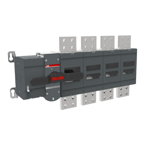
ABB NAL Series User manual

—
DISTRIBUTION SOLUTIONS
Indoor Air Switch-disconnector,
NAL/NALF/VR
Installation and operating instructions
4.16 ... 38 kV / 200...1250 A

2

3
—
Table of contents
006 1.0 Your safety first – always!
006 1.1 General notes
007 1.2 Application highlights
008 2.0 Indoor air switch-
disconnector
009 3.0 Introduction
009 3.1 Main product features
010 4.0 Environmental protection
program
011 5.0 Safety instructions
012 6.0 Recommendations for
receipt, handling and storage
of equipment
012 6.1 Switch-disconnector type
NAL/NALF/VR, alternative
assemblies
013 7.0 Installation
013 7.1 Before installation
013 7.2 Preparation of the switch
for installation. Fig. 1
013 7.4 Preparation of the
supporting structure
014 7.5 Installation of the switch-
disconnector
015 8.0 Cable connections to
NAL/F terminals
015 8.1 How to install the medium
voltage cable lug?
018 9.0 Mounting the hand
operating mechanism type HE

4MOUNTING AND OPERATION MANUAL INDOOR AIR SWITCH-DISCONNECTOR, NAL/NALF/VR
019 9.1 Instruction of installation
and adjustment of switch-
disconnector type NAL/NALF/
VR with hand operation
mechanism HE
024 10.0 Adjustment of the hand
operating, mechanism type HE
024 10.1 Adjustment of the hand
operating, mechanism type HE
024 10.2 K-mechanism. Fig.32
025 10.3 A-mechanism. Fig. 33
026 11.0 Hand operating
mechanism NEMD
026 11.1 Application
026 11.2 Rated data
026 11.3 Working conditions
026 11.4 Design and principle of
operation
027 11.5 Versions available
028 12.0 Replacing the mechanism
on the switch
028 12.1 Replacing the mechanism
on the switch
029 12.2 Test operation of
A-mechanism
030 13.0 Mounting of fuse-base
030 13.1 Mounting of fuse-base
031 13.2 Mounting of the fuse
tripping. Fig. 45
031 13.4 Fuse tripping
—
Table of contents
032 14.0 Mounting of earthing
switch type E
032 14.1 Mounting of earthing
switch type E/EB (Fig.47)
032 14.2 Mounting the earthing
switch to the switch-
disconnector type NAL/VR
033 14.3 Mounting the earthing
switch to the fuse- switch
disconnector type NALF/VR
033 14.4 Mounting the mechanical
interlock between switch-
disconnector and earthing
switch. Fig. 47, 49, 50
033 14.5 Testing the interlock
034 15.0 Mounting the shunt
release
035 16.0 Mounting the auxiliary
switch
035 16.1 Auxiliary switch for
switch-disconnector
035 Connection of the
auxiliary circuits
037 16.2 Mounting the auxiliary
switch for E-EB earthing
switch. Fig. 60-71
039 16.3 Mounting the auxiliary
switch for fuse interruption
042 16.4 Mounting the open fuse
auxiliary switch on motor
bracket
044 17.0 Motor drive
044 17.1 Mounting of NM/MU
motor drive

5
058 21.0 Replacement of parts in
NAL/VR 36 kV
058 21.1 Replacement of contact
knives
059 21.2 Replacement of draw bar.
Fig. 116
059 21.3 Replacement of the
supporting insulator. Fig. 118
060 21.4 Replacement of the
hollow insulator. Fig. 119
060 21.5 Replacement of the
piston with piston rod.
Fig. 120
061 22.0 Adjustment of splined
shaft end for earthing switch.
Fig. 122- 126
062 23.0 Liabilities
063 24.0 Reference list of fuses
068 25.0 Environmental
declaration
068 25.1 Environmental
Certification Life expectancy
of product
068 25.2 End-of-life
045 17.2 Motor drive settings for
A-mechanism
047 17.3 Motor drive settings for
K-mechanism
048 17.4 UEMC 41
049 18.0 Service and maintenance
049 18.1 Cleaning
049 18.2 Switch-disconnector in
service
050 18.3 Mechanical overhaul
050 18.4 Electrical overhaul in
service
050 18.5 Control of NAL/VR knives
after mounting. Fig. 105-106
054 19.0 Replacement of parts
(12-24 kV)
055 19.1 Replacement of contact
knife with draw bar. Fig.110
055 19.2 Pivot side support
insulator. Fig. 110
056 19.3 Replacement of fixed
contact on the opening side
Fig. 111
056 19.4 Replacement of the
arcing chamber. Fig. 111
057 20.0 Replacement of
insulators
057 20.1 Hollow insulators with
arcing chamber. Fig. 113
057 20.2 Insulator for fuse-base
and quick make earthing
switch

6MOUNTING AND OPERATION MANUAL INDOOR AIR SWITCH-DISCONNECTOR, NAL/NALF/VR
—
1.0 Your safety first – always!
That’s why our manual begins with these recommendations:
comply in full with the legally recognized standards (ANSI / IEC)
and the applicable safety regulations at work.
WARNING!
• Pay special attention to the hazard notes in the
manual marked with this warning symbol.
• Make sure that under operation condition of the
switchgear or switchboard the specified data is
not exceeded.
• Keep the manual accessible to all persons
concerned with installation, operation and
maintenance.
• The user’s personnel are to act responsibly in all
matters affecting safety at work and the correct
handling of the switchgear.
• There are hazards of electrical shock and burns
whenever working in or around electrical
equipment. Turn off power before performing
any inspection or maintenance operations.
Check line terminals to verify that the
equipment is de-energized and earthed.
• Check terminals to ensure that no back-feed
condition exists.
If you have any further questions on this manual,
the members of our field organization will be
pleased to provide the required information.
In case of any uncertainty or questions related to
mounting and/or operation which are not
described in the manual please contact ABB.
1.1 General notes:
1. Regular equipment designed for normal
indoor service condition (Class 0 acc. to IEC
62271-304) to be used in locations with
humidity/temperature control (i.e. sufficient
heating source, humidity absorbers, etc.)
and/or buildings with special thermal design
to prevent negative influence of rapid
outside temperature change to avoid
condensation.
2. For the normal indoor service condition
(water condensation max 2 times a year and
low pollution level) there is no need to do any
special test of indoor switch-disconnectors.
For more severe conditions, the substation
with applicable components, needs to be
classified and tested according to IEC 62271-
304.
3. The regular NAL/F and VR with BMC (Bulk
(Dough) Moulding Compounds) insulators is
designed to class 0 (C0PL) that corresponds
to normal indoor service conditions. The
standard NAL/VR works fine everywhere
these operating conditions are provided.
4. Wherever we observe harsh operating
conditions, special type of the switch-
disconnector NAL/F-H is recommended that
has been type tested according to IEC 62271-
304 design class 2 for severe operating
conditions.
5. Regardless of the type of switch-
disconnector in use, all installation work,
station design, location selection, ground
preparation, and maintenance must be done
in a professional way to keep the installation
in good condition throughout it's assumed
lifetime.
6. Correct installation is of primary importance.
The manufacturer’s instructions must be
carefully studied and followed. It is good
practice to use gloves for handling the pieces
during installation.
7. Operations describe in this manual shall be
carried out by specialists only.
8. According to IEC 62271-1 p. 5.12 and IEC
62271-102 p. 5.104.3.1 position of switch-
disconnector has to be clearly indicated.
NAL/NALF/VR air insulated switch-
disconnector allows 100% certainty to
_
WARNING
Always observe the manual and follow the
rules of good engineering practice!
Hazardous voltage can cause electrical
shock and burns. Disconnect power, then
earth and short-circuit before proceeding
with any work on this equipment.
7
1 / 1
1:3
A3
Sheet No.
Format
Language
Scale
Subtitle
Type
Derived from
Name
Date
Location
Revision
Drawn
Checked
Approved
EC No.
EN
Drawing status
Title
Drawing No.
Responsible
ABB Switzerland Ltd
Weight
Material
f
m
c
v
H
L
K
PROPRIETARY AND SECRET INFORMATION
The information contained in this document has to be kept strictly confidential.
Any unauthorized use, reproduction, distribution or disclosure to third parties
is strictly forbidden. ABB reserves all rights regarding Intellectual Property Rights.
Thread Quality Tolerance
"6g-6H" ISO 965
ISO 2768 T.1 Lengths and Angle
ISO 2768 T.2 Geometrical Tolerances
Surface
Surface code
Coord. punching N.C.Mach.
and unfold JS11
Standard Tolerances for Machining and Forming
© Copyright
ABB. All rights reserved.
2016
D
C
8
A
B
E
8
7
6
5
4
3
2
1
A
B
C
D
E
7
6
5
4
3
2
1
Group Technology Management
PL-PSY
M. Mańkowski
PLABB
Opening side
Pivot side
Closed position Open position
Open position
Closed position
Earthing switch
Switch disconnector
per manufacturer instructions. Reduction of
space and installation requirements has
already influenced the design of kiosks and
stations however the proper maintenance is
still required.
• In case it would not be possible to avoid
condensation inside the compartment, the
prefabricated substation must be treated as
class 1 or class 2 as per IEC 62271-304 and all
the products installed inside shall be
upgraded accordingly.
• Regardless of the type of switch-
disconnector, all installation work, station
design, location selection, ground
preparation, and maintenance must be done
in a professional way to keep the installation
in good condition throughout it's assumed
lifetime.
• Final product performance needs to be
tested in final application.
determine the position of the main contacts
which is a big advantage.
9. ABB recommends to verify the position of
the main knives before and after each
operation. ABB recommends to install air-
insulated switch-disconnectors in
applications where it is possible to visually
check main knives position eg. through an
inspection window.
10. Please place attached sticker with drawing
close to inspection window. Before any
operation please check switch position.
1.2 Application highlights
Important factors that influence life time of
prefabricated substation:
• Placement of substations and proximity to
harsh environments (polluted areas and
roads, road salt, farming land and fertilizing
areas, coast areas, salty water, cable ditch
and penetration of ground water and surface
water, removing of snow etc).
• Materials of the substation and possibility of
condensation forming from quick
temperature variations.
• Draining of the ground around the substation
and preparation of the foundation including
backfilling of cable trench.
• Elimination of pollution and humidity.
• Placement of kiosks in terrains.
• Elimination of potential sources of corona in
design and installation: cable terminations,
busbars, sharp edges…
• Heating, better utilization of the heating
from the transformer and ventilation.
Whenever the utilization of heating from
installed distribution transformer is not
sufficient to avoid water dropping
condensation, it is recommended to use
other solutions like heaters, humidity
absorbers, thermal insulation of walls etc. to
keep working environment according to
installed apparatus and equipment class.
• Respect of maintenance plan, to be done as

8MOUNTING AND OPERATION MANUAL INDOOR AIR SWITCH-DISCONNECTOR, NAL/NALF/VR
—
The NAL/NALF/VR family of switch-
disconnectors is characterized by its
compact, modular design and broad
functionality. With their unique design for
extinguishing the electric arc and high
switching capacity, they represent an
attractive solution as the main switching
apparatus for applications in enclosed
switchgear and compact transformer
stations. In combination with ABB CEF
current limiting fuses, they provide reliable
control over the full range of overload
currents.
Main areas of application NAL/NALF/VR
switch-disconnector:
• as line and transformer switches within
distribution networks,
• as motor switches.
—
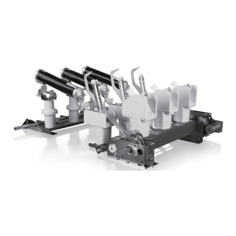
2.0 Indoor Air Switch-disconnector
NAL/NALF/VR
Rated voltage: 4.16 - 38 kV
Rated current: 200 -1250 A

9
—
3.0 Introduction
The NAL/NALF/VR switch-disconnector system is
based on a modular principle. The basic unit
consists of a frame with insulators and current
carrying elements. Two different types of
operating mechanisms: snap action mechanism
type K or stored spring energy mechanism type A,
can be mounted on the frame. Fuse-bases type F
with or without fuse tripping mechanism, and
earthing switch type E/EB, suitable for both
direct mounting and free standing components,
complete the basic switch-disconnector
equipment. These modules can be easily
configured, according to customer requirements.
Accessories such as shunt trip, auxiliary switches,
motor operation and various systems for manual
operation can easily be added.
The NAL/NALF/VR brand is recognized globally
and over 600,000 switches have been produced
so far. The design is subject to continuous
development to meet changing customer needs.
3.1 Main Product Features
NALF/VR is the ideal solution for the protection
of the majority of faults in modern electrical
networks. It combines NAL/VR, which interrupts
load currents (up to 1250A) and small fault
currents, with the fuse-base (F) for breaking large
short-circuit currents. The NAL switch-
disconnector family meets the following
standards (depends on the product variant and
voltage level):
IEC 62271-1, EC 62271-102, IEC 62271-103, IEC
62271-105 (IEC 420 for NALF 36kV), IEC 62271-304,
IEC 60129, IEC 60254, IEC 60694, IEC 420,
regarding indoor switches for general use and for
safe switching coordination between switch-
disconnectors and a current limiting fuse.
NAL meets requirements of IEC 62271-1 p. 2.1
Normal service conditions.
The NAL version for IEEE applications is called
VersaRupter. It meets IEEE Standard No. C37.20.4.
The specified NAL/NALF switch-disconnectors
are listed as certified by the Canadian Standard
Association.
Some VersaRupter styles are UL listed, in terms of
compliance with relevant safety requirements, in
order of their release for use in each region of the
US and installations carried out in accordance
with the UL standard.

10 MOUNTING AND OPERATION MANUAL INDOOR AIR SWITCH-DISCONNECTOR, NAL/NALF/VR
—
4.0 Environmental protection
program
—
The NAL/NALF/VR switch-
disconnectors are manufactured
in accordance with the ISO 14001
Standard (Guidelines for
environmental management).
The production processes are
carried out in compliance with the
Standards for environmental
protection in terms of reduction
in energy consumption as well as
in raw materials and production
of waste materials.
All this is thanks to the medium
voltage apparatus manufacturing
facility environmental
management system.

11
—
5.0 Safety instructions
—
• Comply all general safety rules
during any activities related to
the electrical apparatus under
high voltage.
• Make sure that the apparatus
will be installed in proper
place.
• All maintenance and
installation activities shall be
performed by specialists with
valid licenses only.
• Always follow these
instructions closely.
• If you have any questions or
doubts, please contact the
proper ABB personnel.
• Only original parts provided by
PLABB should be used.
_
WARNING
Careless handling of high voltage can result
in serious injury or death. Before carrying
out of any maintenance/installation
of apparatus, read these instructions
carefully.

12 MOUNTING AND OPERATION MANUAL INDOOR AIR SWITCH-DISCONNECTOR, NAL/NALF/VR
Unload the switch-disconnectors from the vehicle
with the utmost care. Immediately check the
condition of the packaging as soon as the switch-
disconnectors arrive. Make sure that the
apparatus is undamaged and that the data on the
nameplate on the outside of the packaging
corresponds to the information on the order
confirmation and shipping note. If damage or
discrepancies are discovered, or the documents
supplied with the goods fail to correspond,
immediately inform ABB (either directly, or
through your representative or supplier) and the
haulage contractor that made the delivery. The
switch-disconnectors are supplied solely with the
accessories specified at the time of order and
validated in the order confirmation by ABB.
If immediate installation is not possible, please
store covered indoors, in a well-ventilated, dry,
dust-free, non-corrosive atmosphere, away from
any easily flammable materials and at a
temperature between – 5 °C and + 45 °C. Please
consult us if special requirements are involved.
• In any case, avoid any accidental impacts or
positioning which stresses the structure of the
apparatus.
• Check the apparatus condition directly after
receipt. Any damages should be reported to the
transporter forwarder and manufacturer,
• Make sure that the product is complete and
complies with the order.
• Be careful during transportation of apparatus.
• Never lift apparatus by grabbing current knives,
main shaft or insulators, because it may cause
switch damage.
• Before installing, keep switches only in original
boxes and store it as it indicated on the boxes.
• In order to unpack the switch, remove all the
packaging elements first. After that remove the
switch from the box using straps fixed to upper
frame plate. Do not use chains, because it may
cause damage to the apparatus.
6.1 Switch-disconnector type NAL/NALF/VR,
alternative assemblies
The switch-disconnector NAL/NALF/VR is
supplied by the factory as follows:
• Fully assembled with mechanism and
auxiliaries. See item “Installation”
• The following versions are available:
- NAL – IEC/CSA standards as line switch-
disconnectors
- NALF – IEC standard as switch-fuse
combination
- NALFO- IEC standard as switch-fuse
combination with fuse base above hollow
insulators
- NAL-H – IEC standard as line switch-
disconnectors for harsh operating conditions.
- NALF-H – IEC standard as switch-fuse
combination for harsh operating conditions.
- VR – VersaRupter the NAL version for IEEE
standard
—
6.0 Recommendations for receipt,
handling and storage of equipment

13
7.3 Test operations
Switches with K-mechanism will close when the
operating shaft is turned anti-clockwise. The
switch will open when the operation shaft is
turned clockwise. (Clockwise/anti-clockwise as
seen from the mechanism side of the switch).
When operating switches are equipped with
A-mechanism, the opening spring is first charged
and latched by turning the operating shaft
clockwise. Turning the shaft anti-clockwise
charges the closing spring and the switch closes.
The switches open when the operating shaft is
turned clockwise.
7.4 Preparation of the supporting structure
The switch-disconnector is intended for vertical
or horizontal operations. The design of a
supporting structure shall consider the
geometrical configuration of the apparatus
(vertical or horizontal) and minimal clearances to
both earthed and live parts. The supporting
structure shall be rigid enough to avoid some
deformation of the apparatus base. All the
touching points of the supporting structure and
the apparatus base shall lay in the same plane.
—
7.0 Installation
7.1 Before installation
Before installing, carry out visual check of switch.
Make sure that main contacts are greased with
Isoflex Topas NCA 52. In case of NAL 12/17/24/36
with A mechanisms , make sure that the push
rods are removed from the main shaft.
7.2 Preparation of the switch for installation.
Fig. 1
For switches with A-mechanisms, the contact
knives must be fully opened by hand and the draw
bars connected to the cranks. Before the switch is
test operated, it should be checked that the
surfaces of the main contact are covered by
contact grease (recommended grease: ISOFLEX
TOPAS NCA 52). ABB recommends to install this
switch-disconnector in applications where it is
possible to visually check main knives position
e.g. through inspection window.
—
1 Switch-disconnector type NAL/NALF/VR
_
WARNING
Current knives rotate with great speed and
force. Always keep a safe distance from
moving parts of the switch. Be careful with
type A (double spring) mechanism. This
kind of drive stores great energy and can
release it by small rotation of shaft.
_
CAUTION!
In case of A mechanism, after switch
closing or opening (without opening
spring charged) do not turn the
mechanism shaft in the closing direction.
It can cause damage of mechanism. Keep
well clear of contact knives when
operating the switches. During installation
on non-flat surfaces, use shims correcting
inequalities. This will prevent the stress
forces in the switch frame When
inequalities of surface are significant, use
a rigid support structure, e.g. made by
ABB.

14 MOUNTING AND OPERATION MANUAL INDOOR AIR SWITCH-DISCONNECTOR, NAL/NALF/VR
For construction of the supporting structure it is
recommended to use some U-iron or angle iron
components. The apparatus shall be fixed by
means of four M12 bolts arranged according to
the dimensional drawing.
7.5 Installation of the switch-disconnector
In the course of installation of the switch-
disconnector particular attention should be paid
not to deform the base of the apparatus,
otherwise some defects will occur such as the
following:
1. Excessive rise of the starting moment of a
force on the switch-disconnector shaft,
2. Non-simultaneity of the contacts which
should not exceed 3 mm in normal
conditions,
3. Deterioration of contact surface area in the
closed opposition,
4. Displacement of the symmetry plane of
moving contacts in relation to the pole
symmetry plane which results in
asymmetrical touching of the fixed and
moving contacts. In addition, the operating
lever will hit the lock.
To avoid these defects coming from deformations
of the supporting structure it is recommended to
tighten initially three bolts only when fixing the
base. Some additional washers shall be placed
under the fourth bolt to prevent deformations of
the switch base when tightening the fourth bolt.
During installation be careful and do not apply
high (should be 40 Nm +/-10%), torque on the
insulators. When tightening nuts of the rail
mounting bolts, the bolts must be countered.
Whenever special operating conditions apply the
only recommended type of switch-disconnector
is H version that has been designed for
application in harsh operating conditions (design
class 2 according to IEC 62271-304).
_
CAUTION!
If the apparatus will work under conditions
which allow the water deposition or
condensation on apparatus parts or on
elements (busbars) directly connected to
it, the apparatus should not be installed
vertically with hollow insulators at the
bottom. In addition, the apparatus should
be protected against the water dripping or
runoff on its insulating parts. This
situation may cause a dielectric strength
deterioration of apparatus.

15
Cable lugs should always be placed on the upper
side of the switch terminal and face up (Fig.4).
It is recommended to use a is conical spring
washer DIN 6796 mechanical zinc plated.
The length of the fastening bolts used for the
cable lug connections should not protrude beyond
the nut by more than 2-3 threads after tightening.
(Fig.5).
8.1 How to install the medium voltage cable lug?
—
2 Proper cable lug connection
—
3 Proper cable lug connection
—
4 Recommended assembly method of medium voltage cable lug
—
5 Proper connection with the switch-disconnector terminal
Upper side
Lower side
—
8.0 Cable connections to NAL/F
terminals
Max. 2÷3 thread
_
WARNING
Improper installation of cable connections
to the switch-disconnector terminals
cause an operational hazard.

16 MOUNTING AND OPERATION MANUAL INDOOR AIR SWITCH-DISCONNECTOR, NAL/NALF/VR
The connection bolt should be arranged such that
one wrench can be used to hold the bolt head on
the bottom and another can be used to tighten
the nut in the direction of the threads. (Fig. 6,7.)
Proper connection to the switch-disconnector
terminal.
12.0 Improper installation of cable
connections
The connection bolt used is too long. The bolt
should have sufficient length. See Fig. 3.
Cable lug installation on the incorrect side of the
switch terminal. Cable lug cannot be fixed from
the terminal lower side. Fix it as shown on Fig.3.
—
6 Direction of the screw thread
—
7 Recommended method of screwing connection.
—
8 Cable lugs properly connected to the switch-disconnector terminal
—
9 Example of mounting with too long screw
—
10 Example of incorrect cable lug side installation.
_
WARNING!
Improper installation of cable connections
to the switch-disconnector terminals
cause an operational hazard.

17
Cable lug installation on the incorrect side of the
switch terminal. Cable lug cannot be fixed from
the terminal lower side. Fix it as shown on Fig.3.
Cable lug installation on the incorrect side of the
switch terminal. Cable lug cannot face down. Fix it
as shown on Fig.3.
—
11 Example of incorrect cable lug side installation
—
12 Example of incorrect cable lug side installation
_
WARNING!
Ignoring these instructions can cause damage to the equipment:
1. Ensure proper installation of the cable lugs on the terminals
• Do not install cable terminal on the side of the earthing switch
• Do not install cable terminal in reverse way.
• Utilize proper length of bolts in such a way that bolt thread does not excessively protrude from
the cable lug.
2. Ensure good quality work on cable terminations.
3. Ensure that clearances are in accordance to the required voltage level.
For NAL/F installation in the pre-fabricated substations or CSS please refer to manufacturer
manuals. The pre-fabricated substations or CSS manufacturer is responsible for ensuring the
operating conditions in the station according to the design class of installed devices (see IEC
62271-304).
The regular NAL/F with BMC (Bulk (Dough) Moulding Compounds) insulators is designed to class
0 (C0PL) that corresponds to normal service conditions. The standard NAL works fine everywhere
these operating conditions are provided. Wherever we observe harsh operating conditions,
special type of the switch-disconnector NAL/F-H is recommended that has been type tested
according to IEC 62271-304 design class 2 for severe operating conditions.
Regardless of the type of the switch-disconnector in use, all installation work, station design,
location selection, ground preparation, and maintenance must be done in a professional way to
keep the installation in good condition throughout it's lifetime.

18 MOUNTING AND OPERATION MANUAL INDOOR AIR SWITCH-DISCONNECTOR, NAL/NALF/VR
The bevel gears should be mounted with the
switch-disconnector in open position (see Fig. 13)
and should be placed at the end of the shaft to
achieve maximum distance between apparatus
and rod. Two set screws must be tightened after
installing the bevel gears as visible on Fig. 16. The
angle of the operating tube must not exceed 40°,
see Fig. 17. Drilling of the operating tube, see
Fig. 18.
9.1 Instruction of installation and adjustment of
switch-disconnector type NAL/NALF/VR with
hand operation mechanism HE.
—
9.0 Mounting the hand operating
mechanism type HE
_
WARNING
Always apply the information label supplied
with the drive during installation. Stickers
must be close to the drive so they can be
easily viewed by personnel.

19
1. Take out the NAL/VR from the box. Open the
contact knives to maximum position and connect
the drawbars (disconnected for transport) with
shaft. Install NAL/VR on support construction in
open position, see Fig.13.
2. Opening spring is not charged (apply to NAL/
NALF/VR with A mechanism), see Fig. 14.
3. Install the bevel gear on the NAL/NALF/VR and
earthing switch shaft. Be sure the orientation of
the gear wheels has been properly assigned – the
bigger wheel position is important. This position
is clearly shown on Fig. 15. In case of earthing
switch, the knurled end shaft on which the bevel
gear is installed, must be mounted on the
earthing switch shaft using the long-slotted
hole.
—
13 NAL in open position
—
14 A mechanism
—
15 NAL/VR switch disconnector with earthing switch

20 MOUNTING AND OPERATION MANUAL INDOOR AIR SWITCH-DISCONNECTOR, NAL/NALF/VR
S
F
Max. 40°
4. Secure the bevel gear with two screws located
inside the housing with allen key (2,5 size) with
torque 3 Nm (see Fig. 16).
5. Install the hand operating mechanism HE. Put
the connection rod (tube = 26.9 mm) between
cardanic joint and bevel gear. Maximum angle is
40o- see Fig. 17.
6. Mark the position of the hole for the safety pin
hole and do not make a bigger hole than = 10.1
mm (see Fig.18).
—
16 HE hand operating mechanism
—
17 Hand operating mechanism
—
18 Connecting rod
Other manuals for NAL Series
2
This manual suits for next models
2
Table of contents
Other ABB Switch manuals

ABB
ABB Zenith ZTX Series User manual

ABB
ABB Zenith ZBTS T Series User guide

ABB
ABB IS/S 8.1.1 User manual

ABB
ABB LineStrong2 Series User manual

ABB
ABB UniGear Series User manual

ABB
ABB UniSec User manual

ABB
ABB DS1 User manual

ABB
ABB 6953 EB-101-500 User manual

ABB
ABB NE802 User manual

ABB
ABB FIP1001 User manual

ABB
ABB OKL 25 Series User manual

ABB
ABB VUBB User manual

ABB
ABB Zenith ZTG 30 User manual

ABB
ABB SACE Tmax XT5 User manual

ABB
ABB Zenith ZTG T Series User manual

ABB
ABB i-bus KNX 6108/02-500 Parts list manual

ABB
ABB vital 1 User manual

ABB
ABB EDS500 Series User manual

ABB
ABB OTM C 21D User manual

ABB
ABB SafeRing User manual