ABB RET 54 Series Use and care manual

Transformer Terminal
RET 54_
Technical Reference Manual, General


RET 54_
1MRS755225
Issued: 20.01.2005
Version: E/26.10.2010
Transformer Terminal
Technical Reference Manual, General
©Copyright 2005 ABB Oy, Distribution Automation, VAASA, Finland 3
Contents
1. About this manual .....................................................................7
1.1. Copyrights .....................................................................................7
1.2. Trademarks ...................................................................................7
1.3. General .........................................................................................7
1.4. Related documents .......................................................................8
1.5. Document revisions .......................................................................8
2. Safety information .....................................................................9
3. Introduction .............................................................................10
3.1. General .......................................................................................10
3.2. Hardware versions ......................................................................10
4. Instructions ..............................................................................20
4.1. Application ...................................................................................20
4.2. Requirements ..............................................................................23
4.3. Configuration ...............................................................................23
5. Technical Description .............................................................24
5.1. Functional description .................................................................24
5.1.1. Functions of the transformer terminal ..............................24
5.1.1.1. Protection functions ............................................24
5.1.1.2. Measurement functions ......................................25
5.1.1.3. Control functions ................................................26
5.1.1.4. Condition monitoring functions ...........................27
5.1.1.5. Communication functions ...................................27
5.1.1.6. General functions ...............................................28
5.1.1.7. Standard functions .............................................28
5.1.2. Configuration ....................................................................30
5.1.2.1. Transformer terminal configuration ....................30
5.1.2.2. MIMIC configuration ...........................................31
5.1.2.3. LON network configuration .................................33
5.1.2.4. DNP 3.0 and Modbus configuration ...................33
5.1.2.5. Rated frequency .................................................33
5.1.3. Parameters and events ....................................................33
5.1.4. Parameterization ..............................................................34
5.1.4.1. Local parameterization .......................................34
5.1.4.2. External parameterization ..................................34
5.1.4.3. Storing of parameters and recorded data ..........35
5.1.5. Auxiliary voltage ...............................................................35
5.1.5.1. Power supply versions .......................................35
RET 54_
1MRS755225
Issued: 20.01.2005
Version: E/26.10.2010
Transformer Terminal
Technical Reference Manual, General
©Copyright 2005 ABB Oy, Distribution Automation, VAASA, Finland 4
5.1.5.2. Low auxiliary voltage indication ..........................36
5.1.5.3. Overtemperature indication ................................37
5.1.6. Analog channels ..............................................................37
5.1.6.1. Scaling the rated values of the protected unit for
analog channels 39
5.1.6.2. Technical data of the measuring devices ...........39
5.1.6.3. Calculated analog channels ...............................41
5.1.7. Digital inputs ....................................................................41
5.1.7.1. Filter time of a digital input .................................43
5.1.7.2. Inversion of a digital input ..................................43
5.1.7.3. Pulse counters ...................................................44
5.1.7.4. Oscillation suppression ......................................44
5.1.7.5. Attributes of a digital input for transformer terminal
configuration 45
5.1.8. Digital outputs ..................................................................47
5.1.8.1. High-speed double-pole power outputs (HSPO) 48
5.1.8.2. Single-pole power outputs (PO) and a high-speed
single-pole power output (HSPO) 49
5.1.8.3. Double-pole power outputs (PO) ........................49
5.1.8.4. Signal outputs (SO) ............................................50
5.1.9. RTD/analog inputs ...........................................................51
5.1.9.1. Selection of input signal type .............................51
5.1.9.2. Selection of input signal range ...........................51
5.1.9.3. Transducer supervision ......................................53
5.1.9.4. Signal filtering .....................................................53
5.1.9.5. Input scaling/linearization ...................................53
5.1.9.6. Transducer connections .....................................56
5.1.9.7. Attributes of an RTD/analog input for transformer
terminal configuration 59
5.1.9.8. RTD/analog input configuration example ...........59
5.1.9.9. Self-supervision ..................................................60
5.1.9.10.Calibration ..........................................................60
5.1.9.11.RTD temperature vs. resistance ........................61
5.1.10.Analog outputs .................................................................62
5.1.10.1.Selection of analog output range .......................62
5.1.10.2.Attributes of an analog output for transformer
terminal configuration 62
5.1.10.3.Analog output configuration example................. 63
5.1.11.Trip circuit supervision .....................................................64
5.1.11.1.Configuring the trip circuit supervision CMTCS_ 66
5.1.12.Self-supervision (IRF) ......................................................66

RET 54_
1MRS755225
Issued: 20.01.2005
Version: E/26.10.2010
Transformer Terminal
Technical Reference Manual, General
©Copyright 2005 ABB Oy, Distribution Automation, VAASA, Finland 5
5.1.12.1.Fault indication ...................................................67
5.1.12.2.Fault operation ...................................................67
5.1.12.3.Fault recovery ....................................................68
5.1.12.4.Fault codes ........................................................68
5.1.13.Serial communication .......................................................68
5.1.13.1.Serial communication port assignment ..............68
5.1.13.2.SPA/IEC_103 communication on the rear connector
X3.2 69
5.1.13.3.DNP 3.0/Modbus communication on the rear
connector X3.2 69
5.1.13.4.IEC 61850 communication by using SPA-ZC 400 on
the rear connector X3.2 69
5.1.13.5.Profibus-DPV1 communication by using SPA-ZC
302 on the rear connector X3.2 70
5.1.13.6.LON/SPA bus communication on the rear connector
X3.3 70
5.1.13.7.Front panel optical RS-232 connection for a PC 70
5.1.13.8.Communication parameters ...............................70
5.1.13.9.Parallel communication support .........................75
5.1.13.10.System structure ..............................................76
5.1.13.11.LON inputs and outputs via a LON bus ...........81
5.1.13.12.Secured object control .....................................83
5.1.14.Time synchronization .......................................................85
5.1.15.Display panel (HMI) .........................................................85
5.1.16.Alarm LED indicators .......................................................87
5.1.16.1.Non-latched alarm ..............................................88
5.1.16.2.Latched alarm, steady LED ................................88
5.1.16.3.Latched alarm, blinking LEDs ............................89
5.1.16.4.Interlocking .........................................................89
5.2. Design description .......................................................................91
5.2.1. Technical data ..................................................................91
5.2.2. Terminal diagram of RET 541 ..........................................96
5.2.3. Terminal diagram of RET 543 ..........................................97
5.2.4. Terminal diagram of RET 545 ..........................................98
5.2.5. Terminal diagram of the RTD/analog module ..................99
5.2.6. Terminal connections .......................................................99
6. Service ...................................................................................103
7. Ordering Information ............................................................104
7.1. Order number ............................................................................104
7.2. Hardware versions of RET 541, RET 543 and RET 545 ...........105

RET 54_
1MRS755225
Issued: 20.01.2005
Version: E/26.10.2010
Transformer Terminal
Technical Reference Manual, General
©Copyright 2005 ABB Oy, Distribution Automation, VAASA, Finland 6
7.3. Software configuration ..............................................................105
8. Revision History of RET 54_ ................................................106
8.1. Revision identification ...............................................................106
8.2. Patch release, SW build RET 54x Build 4.38 ............................106
8.2.1. Changes and additions to earlier released revisions .....106
8.2.2. Configuration, setting and SA system tools ...................106
9. Abbreviations ........................................................................107
10.Appendix A: The IEC 60870-5-103 bus ...............................108
10.1.Functions supported by the RET 54_ .......................................108
10.2.IEC_103 parameters ................................................................109
10.3.The general principle of application data mapping ...................109
10.4.Class 1 data buffering and priorities .........................................109
10.5.Class 2 data ..............................................................................110
10.5.1.Class 2 measurand sets (ASDU frames) .......................110
10.5.2.Class 2 value scaling .....................................................110
10.6.Default mappings ......................................................................110
10.7.Class 2 measurand sets ...........................................................118
11.Index ......................................................................................121

1MRS755225 Transformer Terminal
Technical Reference Manual, General
RET 54_
7
1. About this manual
1.1. Copyrights
The information in this document is subject to change without notice and should not
be construed as a commitment by ABB Oy. ABB Oy assumes no responsibility for
any errors that may appear in this document.
In no event shall ABB Oy be liable for direct, indirect, special, incidental or
consequential damages of any nature or kind arising from the use of this document,
nor shall ABB Oy be liable for incidental or consequential damages arising from use
of any software or hardware described in this document.
This document and parts thereof must not be reproduced or copied without written
permission from ABB Oy, and the contents thereof must not be imparted to a third
party nor used for any unauthorized purpose.
The software or hardware described in this document is furnished under a license
and may be used, copied, or disclosed only in accordance with the terms of such
license.
Copyright © 2005 ABB Oy
All rights reserved.
1.2. Trademarks
ABB is a registered trademark of ABB Group.
All other brand or product names mentionedin this document may be trademarks or
registered trademarks of their respective holders.
1.3. General
This document, Technical Reference Manual for RET 54_, provides a general
technical description of the transformer terminals RET 541, RET 543 and RET 545.
Version A of the Technical Reference Manual complies with RET 54_ transformer
terminals of the Release 3.0.
For detailed information about the separate protection and other functions listed in
Section 5.1.1., refer to the latest version of the CD-ROM “Technical Descriptions of
Functions”.

8
1MRS755225
Transformer Terminal
Technical Reference Manual, General
RET 54_
1.4. Related documents
1.5. Document revisions
Name of the manual MRS number
General Manuals
Installation Manual 1MRS750526-MUM
Technical Descriptions of Functions (CD-ROM) 1MRS750889-MCD
RE_ 54_ Operator’s Manual 1MRS750500-MUM
Protection & Control Terminals REF 54_, RET 54_, REM 54_,
REC 523 Configuration Guideline 1MRS750745-MUM
RER 103 Bus Connection Module, Technical Description 1MRS750532-MUM
RER 123 Bus Connection Module, Technical Description 1MRS751143-MUM
RER 133 Bus Connection Module, Technical Description 1MRS755163
REF 54_, RET54_, REX 521 DNP 3.0 Communication Protocol,
Technical Description 1MRS755260
REF 54_, RET54_ Modbus Communication Protocol, Technical
Description 1MRS755238
Manuals for RET 54_
Technical Reference Manual, General 1MRS755225
Parameter and event lists for RET 54_
Parameter List for RET 541 and RET 543 1MRS755228
Parameter List for RET 545 1MRS755229
Event List for RET 541 and RET 543 1MRS755226
Event List for RET 545 1MRS755227
Manuals for related products
SPA-ZC 302 Profibus-DPV1/SPA Gateway, Installation and
Commissioning Manual 1MRS755014
SPA-ZC 400 Ethernet Adapter, Installation and Commissioning
Manual 1MRS755347
Tool-specific manuals
CAP 505 Installation and Commissioning Manual 1MRS751901-MEN
CAP 505 User’s Guide 1MRS752292-MUM
CAP 505 Protocol Mapping Tool, Operation Manual 1MRS755277
CAP 505 Relay Mimic Editor, Configuration Guide 1MRS751904-MEN
LIB, CAP, SMS, Tools for Relays and Terminals, User’s Guide 1MRS752008-MUM
LNT 505 Operator’s manual 1MRS751706-MUM
CAP 501 Installation and Commissioning Manual 1MRS751899-MEN
CAP 501 User’s Guide 1MRS751900-MUM
Version Date History
A 20.1.2005 Manual created
B 2.5.2005 Minor revision
C 27.06.2008 Protocol & communication bus details added
D 27.05.2010 Manual updated
E 26.10.2010 Manual updated

1MRS755225 Transformer Terminal
Technical Reference Manual, General
RET 54_
9
2. Safety information
Dangerous voltages can occur on the connectors, even though the
auxiliary voltage has been disconnected.
National and local electrical safety regulations must always be
followed.
The device contains components which are sensitive to electrostatic
discharge. Unnecessary touching of electronic components must
therefore be avoided.
The frame of the device has to be carefully earthed.
Only a competent electrician is allowed to carry out the electrical
installation.
Non-observance can result in death, personal injury or substantial
property damage.
Breaking the sealing tape on the upper handle of the device will result
in loss of warranty and proper operation will no longer be guaranteed.
When the plug-in unit has been detached from the case, do not touch
the inside of the case. The relay case internals may contain high
voltage potential and touching these may cause personal injury.
!

10
1MRS755225
Transformer Terminal
Technical Reference Manual, General
RET 54_
3. Introduction
3.1. General
The RET 54_ transformer terminal is part of the ABB Distribution Automation
system and extends the functionality and flexibility of the concept further. This is
possible due to the modern technology applied both in hardware and software
solutions.
Increased performance is achieved by utilizing the multiprocessor architecture.
Digital signal processing combined with a powerful CPU and distributed I/O
handling facilitates parallel operations and improves response times and accuracy.
The HMI including an LCD display with different views makes the local use of the
RET 54_ transformer terminal safe and easy. The HMI1instructs the user how to
proceed.
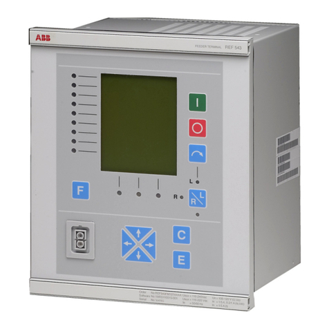
RET543right
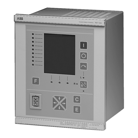
Fig. 3.1.-1 RET 54_ transformer terminal
3.2. Hardware versions
The family of RET 54_ transformer terminals contains several hardware versions.
Depending on the number of I/Os available, the product is called RET 541, RET 543
or RET 545, see the following tables.
1. HMI is referred to as MMI in the terminal and in the Relay Setting Tool

1MRS755225 Transformer Terminal
Technical Reference Manual, General
RET 54_
11
Table 3.2.-1 Hardware versions of RET 541, 6I/3U transformers
HW modules
Order number
RET541A_230AAAA
RET541A_230BAAA
RET541A_230CAAA
RET541A_230AAAB
RET541A_230BAAB
RET541A_233AAAA
RET541A_233BAAA
RET541A_233CAAA
RET541A_233AAAB
RET541A_233BAAB
Analog interface
Currenttrafo1/5A 6666666666
Voltage trafo 100 V 3333333333
Main processor boards
CPU module 1111111111
Power supply boards
PS1: 80...265 VDC/AC (High) 1 1 1 1
PS1: 80...265 VDC /AC (Medium) 1 1 1 1
PS1: 18...80 VDC/ (Low) 1 1
PS2: 80...265 VDC /AC
PS2: 18...80 VDC
Digital I/O boards
BIO1: threshold voltage 155 VDC 1 1 1 1
BIO1: threshold voltage 80 VDC 1 1 1 1
BIO1: threshold voltage 18 VDC 1 1
BIO2: threshold voltage 155 VDC
BIO2: threshold voltage 80 VDC
BIO2: threshold voltage 18 VDC
Analog I/O board
RTD/analog module 11111
Display boards
Graphic HMI display, fixed 1 1 1 1 1 1
Graphic HMI display, external 1 1 1 1
Mechanic
1/2enclosure 1111111111
Digital inputs 15 15
Power outputs, single pole 00
Power outputs, double pole 55
Signal outputs (NO) 22
Signal outputs (NO/NC) 55
Supervised trip circuits 22
IRF outputs 11
RTD/analog inputs 08
Analog outputs 04

12
1MRS755225
Transformer Terminal
Technical Reference Manual, General
RET 54_
Table 3.2.-2 Hardware versions of RET 541, 7I/2U transformers
HW modules
Order number
RET541A_231AAAA
RET541A_231BAAA
RET541A_231CAAA
RET541A_231AAAB
RET541A_231BAAB
RET541A_234AAAA
RET541A_234BAAA
RET541A_234CAAA
RET541A_234AAAB
RET541A_234BAAB
Analog interface
Currenttrafo1/5A 7777777777
Voltage trafo 100 V 2222222222
Main processor boards
CPU module 1111111111
Power supply boards
PS1: 80...265 VDC/AC (High) 1 1 1 1
PS1: 80...265 VDC /AC (Medium) 1 1 1 1
PS1: 18...80 VDC (Low) 1 1
PS2: 80...265 VDC /AC
PS2: 18...80 VDC
Digital I/O boards
BIO1: threshold voltage 155 VDC 1 1 1 1
BIO1: threshold voltage 80 VDC 1 1 1 1
BIO1: threshold voltage 18 VDC 1 1
BIO2: threshold voltage 155 VDC
BIO2: threshold voltage 80 VDC
BIO2: threshold voltage 18 VDC
Analog I/O board
RTD/analog module 11111
Display boards
Graphic HMI display, fixed 1 1 1 1 1 1
Graphic HMI display, external 1 1 1 1
Mechanic
1/2enclosure 1111111111
Digital inputs 15 15
Power outputs, single pole 00
Power outputs, double pole 55
Signal outputs (NO) 22
Signal outputs (NO/NC) 55
Supervised trip circuits 22
IRF outputs 11
RTD/analog inputs 08
Analog outputs 04

1MRS755225 Transformer Terminal
Technical Reference Manual, General
RET 54_
13
Table 3.2.-3 Hardware versions of RET 541, 8I/1U transformers
HW modules
Order number
RET541A_232AAAA
RET541A_232BAAA
RET541A_232CAAA
RET541A_232AAAB
RET541A_232BAAB
RET541A_235AAAA
RET541A_235BAAA
RET541A_235CAAA
RET541A_235AAAB
RET541A_235BAAB
Analog interface
Currenttrafo1/5A 8888888888
Voltage trafo 100 V 1111111111
Main processor boards
CPU module 1111111111
Power supply boards
PS1: 80...265 VDC/AC (High) 1 1 1 1
PS1: 80...265 VDC /AC (Medium) 1 1 1 1
PS1: 18...80 VDC (Low) 1 1
PS2: 80...265 VDC /AC
PS2: 18...80 VDC
Digital I/O boards
BIO1: threshold voltage 155 VDC 1 1 1 1
BIO1: threshold voltage 80 VDC 1 1 1 1
BIO1: threshold voltage 18 VDC 1 1
BIO2: threshold voltage 155 VDC
BIO2: threshold voltage 80 VDC
BIO2: threshold voltage 18 VDC
Analog I/O board
RTD/analog module 11111
Display boards
Graphic HMI display, fixed 1 1 1 1 1 1
Graphic HMI display, external 1 1 1 1
Mechanic
1/2enclosure 1111111111
Digital inputs 15 15
Power outputs, single pole 00
Power outputs, double pole 55
Signal outputs (NO) 22
Signal outputs (NO/NC) 55
Supervised trip circuits 22
IRF outputs 11
RTD/analog inputs 08
Analog outputs 04

14
1MRS755225
Transformer Terminal
Technical Reference Manual, General
RET 54_
Table 3.2.-4 Hardware versions of RET 543, 6I/3U transformers
HW modules
Order number
RET543A_240AAAA
RET543A_240BAAA
RET543A_240CAAA
RET543A_240AAAB
RET543A_240BAAB
RET543A_243AAAA
RET543A_243BAAA
RET543A_243CAAA
RET543A_243AAAB
RET543A_243BAAB
Analog interface
Currenttrafo1/5A 6666666666
Voltage trafo 100 V 3333333333
Main processor boards
CPU module 1111111111
Power supply boards
PS1: 80...265 VDC/AC (High) 1 1 1 1
PS1: 80...265 VDC/AC (Medium) 1 1 1 1
PS1: 18...80 VDC (Low) 1 1
PS2: 80...265 VDC /AC
PS2: 18...80 VDC
Digital I/O boards
BIO1: threshold voltage 155 VDC 1 1 1 1
BIO1: threshold voltage 80 VDC 1 1 1 1
BIO1: threshold voltage 18 VDC 1 1
BIO2: threshold voltage 155 VDC 1 1 1 1
BIO2: threshold voltage 80 VDC 1 1 1 1
BIO2: threshold voltage 18 VDC 1 1
Analog I/O board
RTD/analog module 11111
Display boards
Graphic HMI display, fixed 1 1 1 1 1 1
Graphic HMI display, external 1 1 1 1
Mechanic
1/2enclosure 1111111111
Digital inputs 25 25
Power outputs, single pole 22
Power outputs, double pole 99
Signal outputs (NO) 22
Signal outputs (NO/NC) 55
Supervised trip circuits 22
IRF outputs 11
RTD/analog inputs 08
Analog outputs 04

1MRS755225 Transformer Terminal
Technical Reference Manual, General
RET 54_
15
Table 3.2.-5 Hardware versions of RET 543, 7I/2U transformers
HW modules
Order number
RET543A_241AAAA
RET543A_241BAAA
RET543A_241CAAA
RET543A_241AAAB
RET543A_241BAAB
RET543A_244AAAA
RET543A_244BAAA
RET543A_244CAAA
RET543A_244AAAB
RET543A_244BAAB
Analog interface
Currenttrafo1/5A 7777777777
Voltage trafo 100 V 2222222222
Main processor boards
CPU module 1111111111
Power supply boards
PS1: 80...265 VDC/AC (High) 1 1 1 1
PS1: 80...265 VDC/AC (Medium) 1 1 1 1
PS1: 18...80 VDC (Low) 1 1
PS2: 80...265 VDC /AC
PS2: 18...80 VDC
Digital I/O boards
BIO1: threshold voltage 155 VDC 1 1 1 1
BIO1: threshold voltage 80 VDC 1 1 1 1
BIO1: threshold voltage 18 VDC 1 1
BIO2: threshold voltage 155 VDC 1 1 1 1
BIO2: threshold voltage 80 VDC 1 1 1 1
BIO2: threshold voltage 18 VDC 1 1
Analog I/O board
RTD/analog module 11111
Display boards
Graphic HMI display, fixed 1 1 1 1 1 1
Graphic HMI display, external 1 1 1 1
Mechanic
1/2enclosure 1111111111
Digital inputs 25 25
Power outputs, single pole 22
Power outputs, double pole 99
Signal outputs (NO) 22
Signal outputs (NO/NC) 55
Supervised trip circuits 22
IRF outputs 11
RTD/analog inputs 08
Analog outputs 04

16
1MRS755225
Transformer Terminal
Technical Reference Manual, General
RET 54_
Table 3.2.-6 Hardware versions of RET 543, 8I/1U transformers
HW modules
Order number
RET543A_242AAAA
RET543A_242BAAA
RET543A_242CAAA
RET543A_242AAAB
RET543A_242BAAB
RET543A_245AAAA
RET543A_245BAAA
RET543A_245CAAA
RET543A_245AAAB
RET543A_245BAAB
Analog interface
Currenttrafo1/5A 8888888888
Voltage trafo 100 V 1111111111
Main processor boards
CPU module 1111111111
Power supply boards
PS1: 80...265 VDC/AC (High) 1 1 1 1
PS1: 80...265 VDC/AC (Medium) 1 1 1 1
PS1: 18...80 VDC (Low) 1 1
PS2: 80...265 VDC /AC
PS2: 18...80 VDC
Digital I/O boards
BIO1: threshold voltage 155 VDC 1 1 1 1
BIO1: threshold voltage 80 VDC 1 1 1 1
BIO1: threshold voltage 18 VDC 1 1
BIO2: threshold voltage 155 VDC 1 1 1 1
BIO2: threshold voltage 80 VDC 1 1 1 1
BIO2: threshold voltage 18 VDC 1 1
Analog I/O board
RTD/analog module 11111
Display boards
Graphic HMI display, fixed 1 1 1 1 1 1
Graphic HMI display, external 1 1 1 1
Mechanic
1/2enclosure 1111111111
Digital inputs 25 25
Power outputs, single pole 22
Power outputs, double pole 99
Signal outputs (NO) 22
Signal outputs (NO/NC) 55
Supervised trip circuits 22
IRF outputs 11
RTD/analog inputs 08
Analog outputs 04

1MRS755225 Transformer Terminal
Technical Reference Manual, General
RET 54_
17
Table 3.2.-7 Hardware versions of RET 545, 6I/3U transformers
HW modules Order number
RET545A_250AAAA
RET545A_250BAAA
RET545A_250CAAA
RET545A_250AAAB
RET545A_250BAAB
Analog interface
Currenttrafo1/5A 66666
Voltage trafo 100 V 33333
Main processor boards
CPU module 11111
Power supply boards
PS1: 80...265 VDC/AC (High)
PS1: 80...265 VDC/AC (Medium)
PS1: 18...80 VDC (Low)
PS2: 80...265 VDC /AC 1 1 1 1
PS2: 18...80 VDC 1
Digital I/O boards
BIO1: threshold voltage 155 VDC 2 2
BIO1: threshold voltage 80 VDC 2 2
BIO1: threshold voltage 18 VDC 2
BIO2: threshold voltage 155 VDC 1 1
BIO2: threshold voltage 80 VDC 1 1
BIO2: threshold voltage 18 VDC 1
Analog I/O board
RTD/analog module
Display boards
Graphic HMI display, fixed 1 1 1
Graphic HMI display, external 1 1
Mechanic
1/2enclosure 11111
Digital inputs 34
Power outputs, single pole 3
Power outputs, double pole 11
Signal outputs (NO) 4
Signal outputs (NO/NC) 8
Supervised trip circuits 2
IRF outputs 1
RTD/analog inputs 0
Analog outputs 0

18
1MRS755225
Transformer Terminal
Technical Reference Manual, General
RET 54_
Table 3.2.-8 Hardware versions of RET 545, 7I/2U transformers
HW modules Order number
RET545A_251AAAA
RET545A_251BAAA
RET545A_251CAAA
RET545A_251AAAB
RET545A_251BAAB
Analog interface
Currenttrafo1/5A 77777
Voltage trafo 100 V 22222
Main processor boards
CPUmodule 11111
Power supply boards
PS1: 80...265 VDC/AC (High)
PS1: 80...265 VDC/AC (Medium)
PS1: 18...80 VDC (Low)
PS2: 80...265 VDC /AC 1 1 1 1
PS2: 18...80 VDC 1
Digital I/O boards
BIO1: threshold voltage 155 VDC 2 2
BIO1: threshold voltage 80 VDC 2 2
BIO1: threshold voltage 18 VDC 2
BIO2: threshold voltage 155 VDC 1 1
BIO2: threshold voltage 80 VDC 1 1
BIO2: threshold voltage 18 VDC 1
Analog I/O board
RTD/analog module
Display boards
Graphic HMI display, fixed 1 1 1
Graphic HMI display, external 1 1
Mechanic
1/2enclosure 11111
Digital inputs 34
Power outputs, single pole 3
Power outputs, double pole 11
Signal outputs (NO) 4
Signal outputs (NO/NC) 8
Supervised trip circuits 2
IRF outputs 1
RTD/analog inputs 0
Analog outputs 0

1MRS755225 Transformer Terminal
Technical Reference Manual, General
RET 54_
19
Table 3.2.-9 Hardware versions of RET 545, 8I/1U transformers
HW modules Order number
RET545A_252AAAA
RET545A_252BAAA
RET545A_252CAAA
RET545A_252AAAB
RET545A_252BAAB
Analog interface
Currenttrafo1/5A 88888
Voltage trafo 100 V 11111
Main processor boards
CPU module 11111
Power supply boards
PS1: 80...265 VDC/AC (High)
PS1: 80...265 VDC/AC (Medium)
PS1: 18...80 VDC (Low)
PS2: 80...265 VDC /AC 1 1 1 1
PS2: 18...80 VDC 1
Digital I/O boards
BIO1: threshold voltage 155 VDC 2 2
BIO1: threshold voltage 80 VDC 2 2
BIO1: threshold voltage 18 VDC 2
BIO2: threshold voltage 155 VDC 1 1
BIO2: threshold voltage 80 VDC 1 1
BIO2: threshold voltage 18 VDC 1
Analog I/O board
RTD/analog module
Display boards
Graphic HMI display, fixed 1 1 1
Graphic HMI display, external 1 1
Mechanic
1/2enclosure 11111
Digital inputs 34
Power outputs, single pole 3
Power outputs, double pole 11
Signal outputs (NO) 4
Signal outputs (NO/NC) 8
Supervised trip circuits 2
IRF outputs 1
RTD/analog inputs 0
Analog outputs 0

20
1MRS755225
Transformer Terminal
Technical Reference Manual, General
RET 54_
4. Instructions
4.1. Application
RET 541/543/545 transformer terminals are designed to be used for the protection,
control, measurement and supervision of two-winding power transformers and
generator-transformer blocks in distribution networks. RET 54_ terminals can also
be used in harsh environments e.g. in heavy industry, marine and off-shore
applications.
The main protection function is three-phase current differential protection with
stabilized and instantaneous stages for fast and selective winding short-circuit and
interturn protection. Besides 2nd and 5th harmonic restraints, the stabilized stage
also includes a waveform recognition-based blocking-deblocking feature. Reliable
operation even with partially saturated current transformers, that is, short operate
times at faults occurring in the zone to be protected and high stability at external
faults are achieved. Increased sensitivity can be obtained by automatic adaptation to
the positionchanges of the on load tap changer. Interposing current transformers are
not needed: Any vector group matching and CT ratio corrections in a wide range are
numerically implemented as well as zero-sequence current elimination, which
prevents unwanted trips at earth faults occurring outside the protected area.
In addition to the differential protection, the Basic version terminals incorporate the
following protections: Restricted earth fault protection with stabilized numerical or
high impedance principle, unbalance and thermal overload protections, three phase
overcurrent and directional or non-directional earth fault back-up protection with
definite and IDMT characteristics on both sides of the transformer.
The Multi-version terminals, including further overvoltage and undervoltage,
residualovervoltage,underfrequencyandoverfrequency, overexcitation,directional
overcurrent and underimpedance line back-up protections, fulfil the most
demanding application requirements.
With the optional automatic voltage regulation function, RET 54_ transformer
terminal can be applied as a comprehensive integrated transformer management
terminal. The voltage regulator can be applied for a single transformer or for parallel
transformers with Master-Follower, Negative Reactance or Minimizing Circulating
Current principles.
A special Control version terminal with just voltage regulator and control functions
can be applied, when integration of voltage regulation and protection is not allowed.
For an example of an application with basic functions, see Figure 4.1.-1.
This manual suits for next models
3
Table of contents
Other ABB Touch Terminal manuals

ABB
ABB REF 54 Series Use and care manual

ABB
ABB REF 541 User manual

ABB
ABB REO 517 Instructions for use

ABB
ABB REM 54 Series Product manual

ABB
ABB SPAC 536 C User manual

ABB
ABB REL 551-C1 2.3 Series Guide

ABB
ABB REL 551 2.5 User manual

ABB
ABB RE 54 User manual

ABB
ABB SPAC 310 C Parts list manual

ABB
ABB CP410 User manual

ABB
ABB REL 551-C1*2.5 Product manual

ABB
ABB REF 541 User manual

ABB
ABB REB 551-C3*2.5 Guide

ABB
ABB REC 561 User manual

ABB
ABB SPAC 315 C Parts list manual

ABB
ABB Symphony Harmony Series User manual

ABB
ABB SPAC 531 C Parts list manual

ABB
ABB Protect IT REL 501 2.5 Series User manual

ABB
ABB REF 54 Series Product manual

ABB
ABB SACE Tmax XT User manual