Page 9
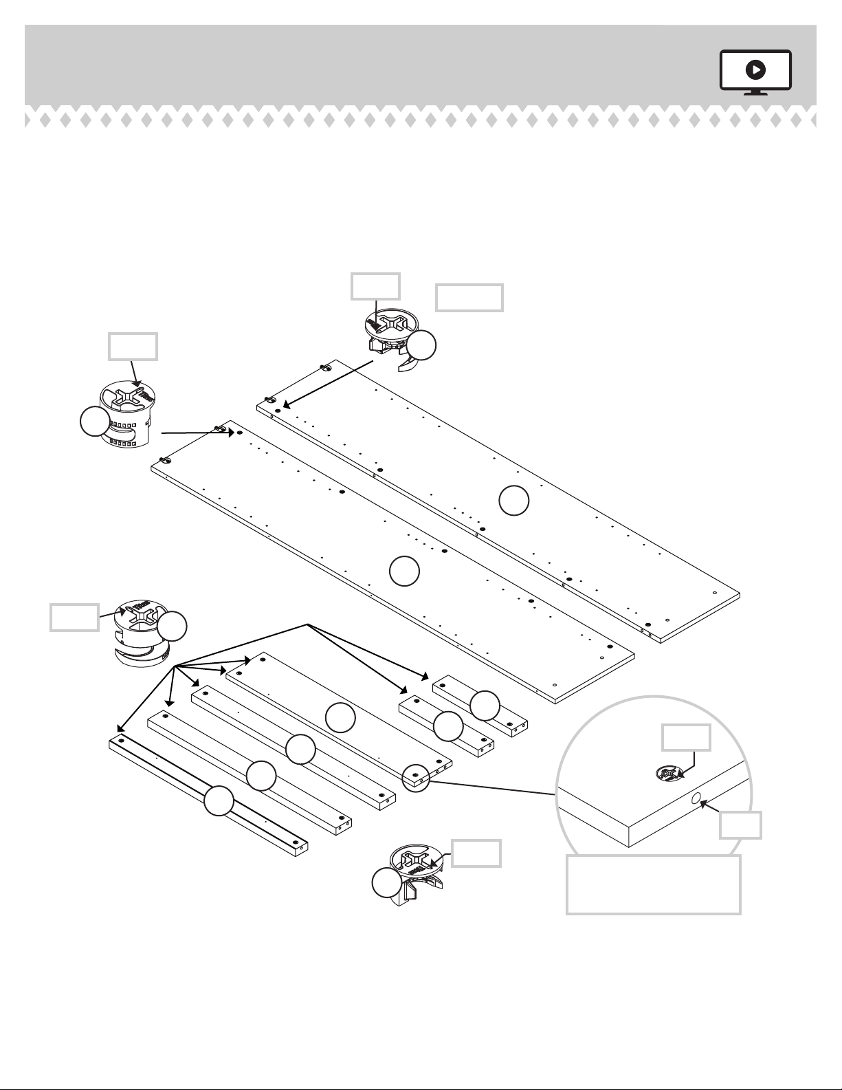
Step 5
A
Surface with
HIDDEN CAMS
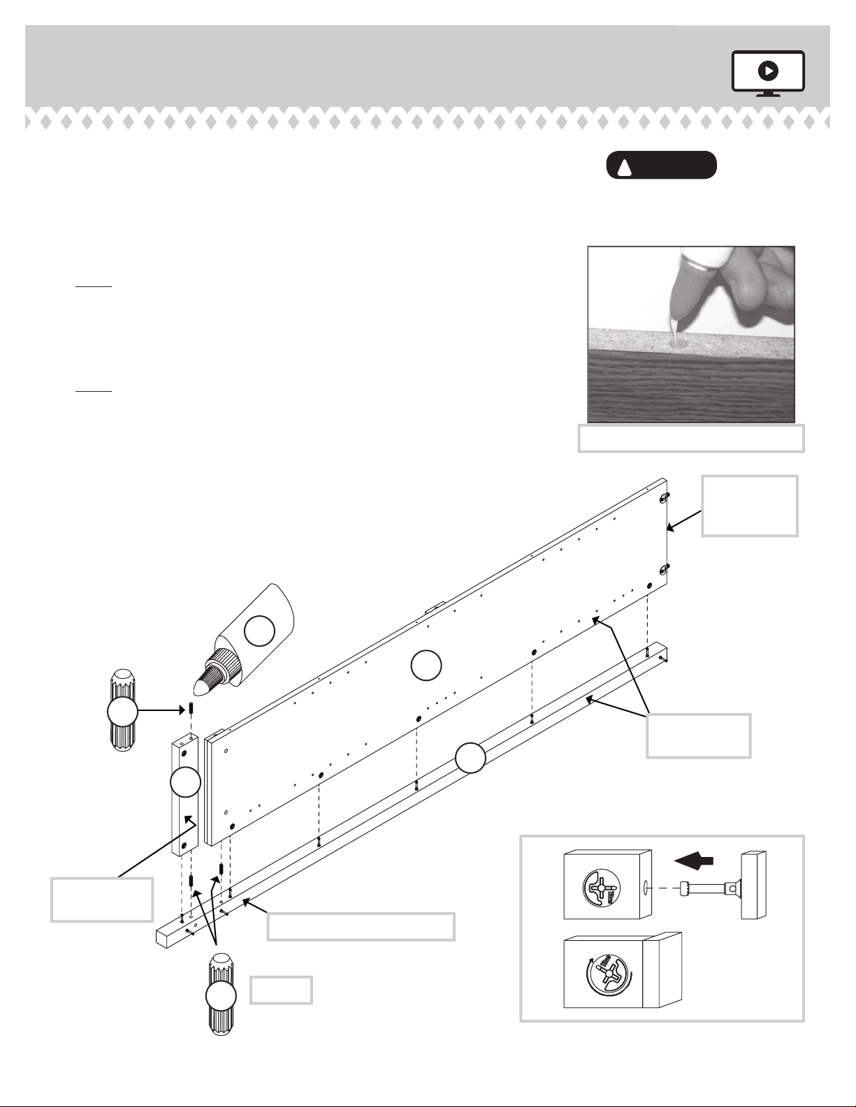
åFirst, fill the holes in the LEG (I) 1/4 to 1/2 full with GLUE (54M). Then, insert
two WOOD DOWELS (15F) into the holes. Wipe away the excess GLUE.
åNow, fill the hole in the END (A) 1/4 to 1/2 full with GLUE.
åFasten the END (A) to the LEG (I). Tighten five HIDDEN CAMS. Wipe away the
excess GLUE.
åNOTE: Be sure the WOOD DOWEL in the LEG inserts into the hole in the END.
åNow, fill the hole in the SIDE SKIRT (O) 1/4 to 1/2 full with GLUE (54M).
åFasten the SIDE SKIRT (O) to the LEG (I). Tighten the HIDDEN CAM. Wipe
away the excess GLUE.
åNOTE: Be sure the WOOD DOWEL in the LEG inserts into the hole in the
SIDE SKIRT.
åLast, fill the hole in the short edge of the SIDE SKIRT (O). Push a WOOD
DOWEL (15F) into the hole. Wipe away the excess GLUE.
1
2
I
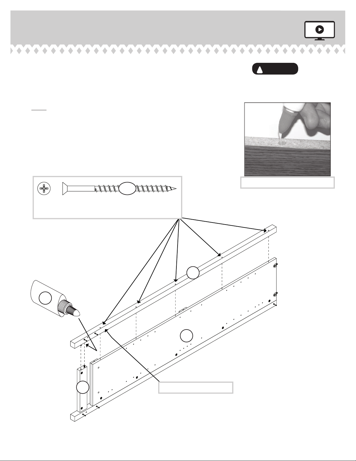
Fill the holes 1/4 to 1/2 full with GLUE.
Inspect the parts thoroughly before
assembling. Disassembly of glued
parts is extremely dicult.
Caution
!
15F
Edge with
FASTENERS
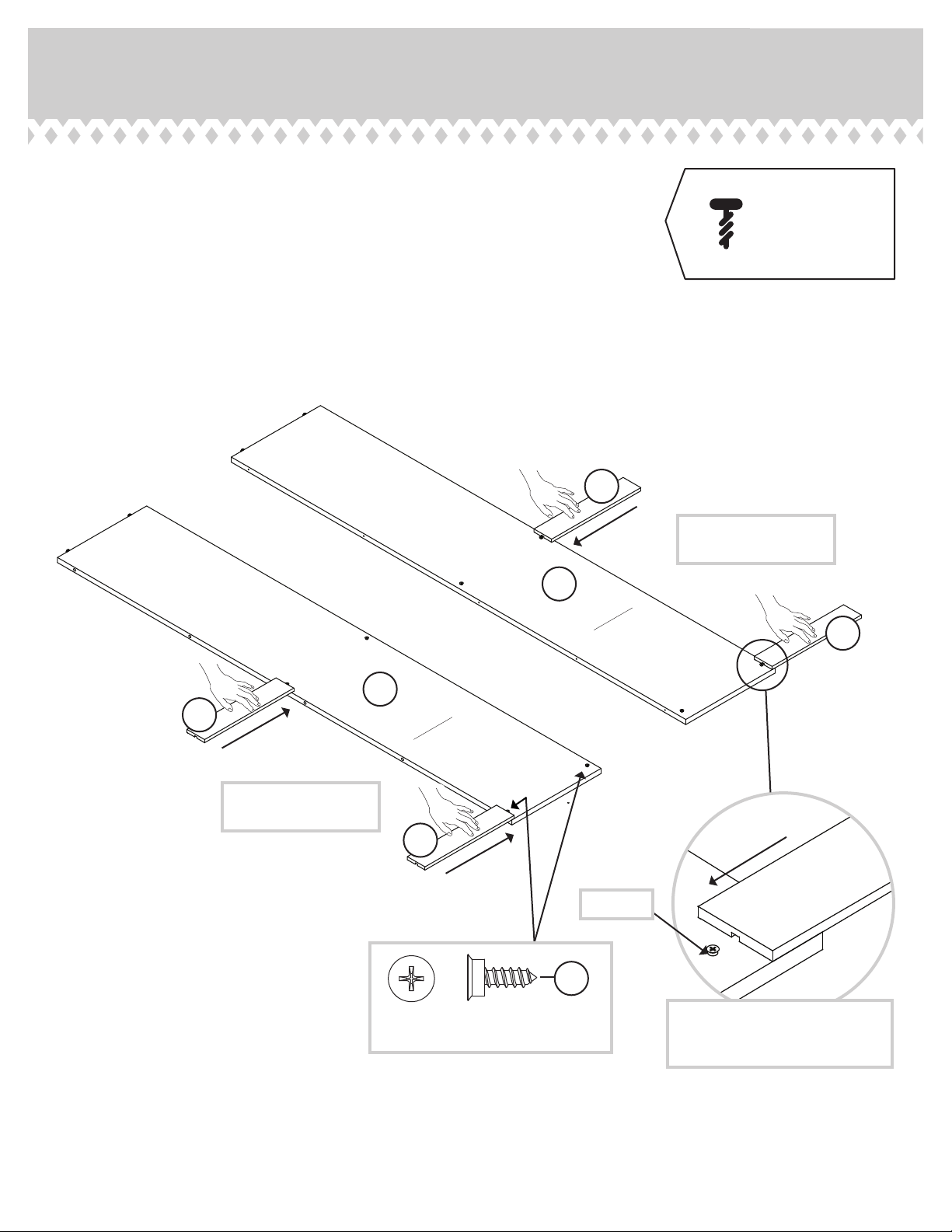
These surfaces
should be even.
Edge with three CAM SCREWS
O
Surface with
HIDDEN CAMS
15F
54M
(3 used)