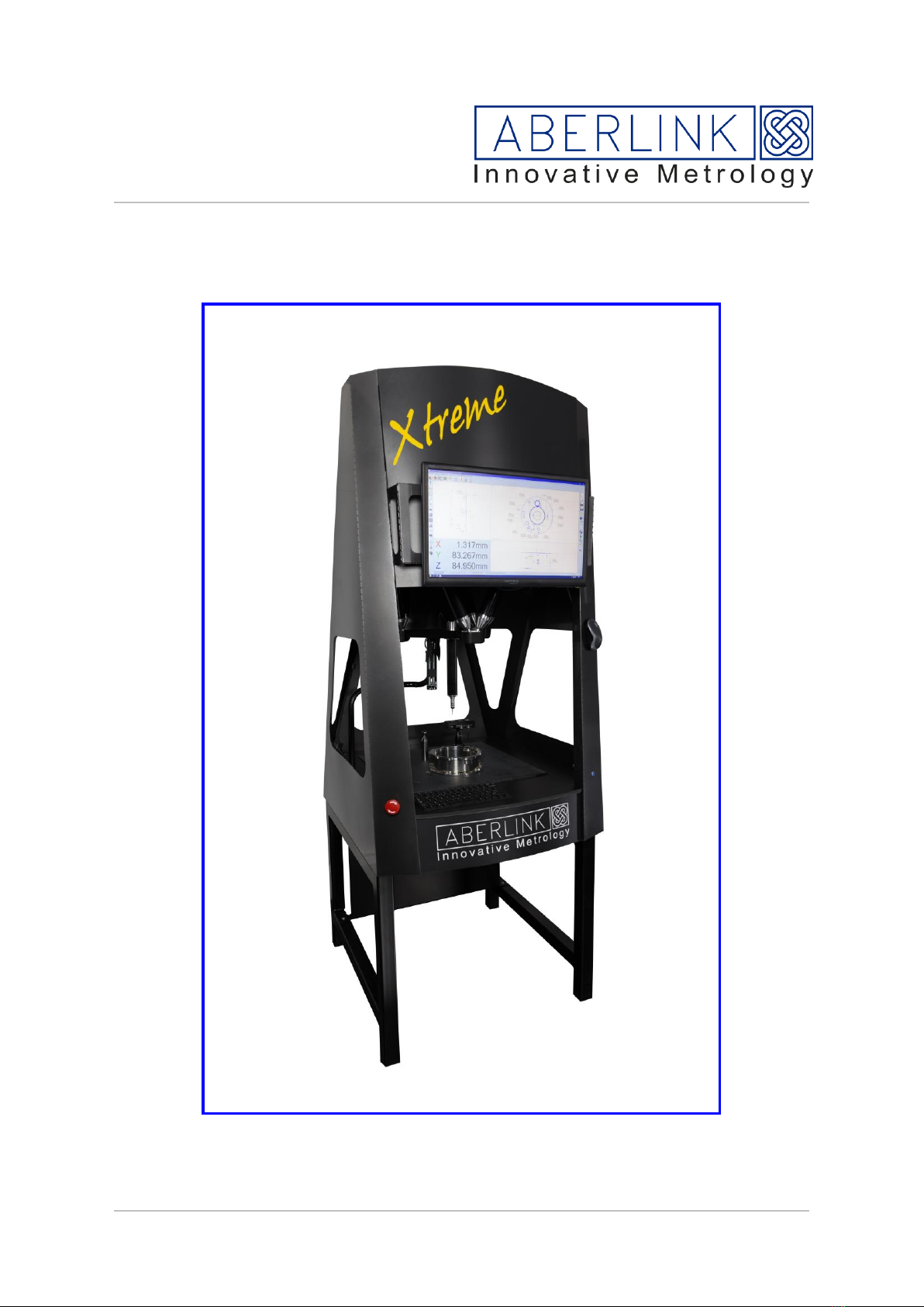
ABERLINK Xtreme User manual

ABERLINK LTD |VATCH LANE |EASTCOMBE |GLOUCESTERSHIRE | GL6 7DY |UK
Tel : +44 (0)1453 884461 | Fax : +44 (0)1453 882348 |
Registered in England No. 7642245 |
VAT Registration No. GB 108 307 537
Xtreme installation manual
Last update 12th April 2017 iss 5

ABERLINK LTD |VATCH LANE |EASTCOMBE |GLOUCESTERSHIRE | GL6 7DY |UK
Tel : +44 (0)1453 884461 | Fax : +44 (0)1453 882348 |
Email : sales@aberlink.co.uk | Web : www.aberlink.com
Registered in England No. 7642245 |
VAT Registration No. GB 108 307 537
The machine will arrive in a single crate,
Package 1 Wooden crate
Contents Machine
Bench
Computer equipment
Machine Accessories
Step 1
Remove the lid, secured by wood screws
Remove screws from the bottom of the crate, and then lift the 4 sides above the machine.
Remove the 3 cap head screws (M10) from the underside of the pallet
Tools Required.
Set of metric allen keys
13 or 15mm Spanner
Cross head screwdriver
Cable ties
Calibration equipment..
200mm slip
200mm ballbar
Ring gauge

ABERLINK LTD |VATCH LANE |EASTCOMBE |GLOUCESTERSHIRE | GL6 7DY |UK
Tel : +44 (0)1453 884461 | Fax : +44 (0)1453 882348 |
Email : sales@aberlink.co.uk | Web : www.aberlink.com
Registered in England No. 7642245 |
VAT Registration No. GB 108 307 537
Step 2
Assemble bench using the M8 button head bolts, the power supply for the machine and a
switch block is attached to the rear panel, the NUC (computer) needs to be attached.
Step 3
Lift the machine from the pallet (2 people), and place diagonally across the bench, this will
allow the studding to be screwed into position (3 places), use a nut to lock the stud in
place, then wind on a second nut (face down) as a location stop, once machine is placed
onto the bench, locating on the three studs, depending on age, studs maybe M6,M8 or
M10
Once on the bench, use a third nut to secure
machine to bench
Fasten the NUC with screws
provided, M3 X 12 with plastic
spacer

ABERLINK LTD |VATCH LANE |EASTCOMBE |GLOUCESTERSHIRE | GL6 7DY |UK
Tel : +44 (0)1453 884461 | Fax : +44 (0)1453 882348 |
Email : sales@aberlink.co.uk | Web : www.aberlink.com
Registered in England No. 7642245 |
VAT Registration No. GB 108 307 537
Step 4
Remove the M3 & M6 cap heads from the transport bracket
securing the probe plate.
Step 6
The counterbalance is shipped un-attached, simply connect the wire, push the cable into
the hole and place the end of the counterbalance into the location hole

ABERLINK LTD |VATCH LANE |EASTCOMBE |GLOUCESTERSHIRE | GL6 7DY |UK
Tel : +44 (0)1453 884461 | Fax : +44 (0)1453 882348 |
Email : sales@aberlink.co.uk | Web : www.aberlink.com
Registered in England No. 7642245 |
VAT Registration No. GB 108 307 537
Step 5
Angle the platform to enable the ruby ball on the tip of the balance to locate in the small
hole, apply a small amount of oil to aid lubrication. Push the probe cable through the bush
so it protrudes below the platform.
Step 6
Locate the probe quill, push connectors together and fit the quill to the probe plate using 3
M3 cap heads

ABERLINK LTD |VATCH LANE |EASTCOMBE |GLOUCESTERSHIRE | GL6 7DY |UK
Tel : +44 (0)1453 884461 | Fax : +44 (0)1453 882348 |
Email : sales@aberlink.co.uk | Web : www.aberlink.com
Registered in England No. 7642245 |
VAT Registration No. GB 108 307 537
Step 7
Fit the monitor, there are 4 cables behind the monitor bracket, a HDMI cable, power cord
USB connector (touch screen only) and a VGA cable, the VGA cable allows the engineer
to view the boot up screen of the top controller for diagnostic purposes.
Step 8
Connect cables to machine and the NUC (Computer), all the cables exit the machine from
the back panel.
To cater for variations in power plugs throughout the world, the switch block is fitted with a
AC power socket.
Connect power supply for the machine,

ABERLINK LTD |VATCH LANE |EASTCOMBE |GLOUCESTERSHIRE | GL6 7DY |UK
Tel : +44 (0)1453 884461 | Fax : +44 (0)1453 882348 |
Email : sales@aberlink.co.uk | Web : www.aberlink.com
Registered in England No. 7642245 |
VAT Registration No. GB 108 307 537
Ethernet connection –to the
NUC
HDMI cable –to the NUC
3 pin plug –to switch block
USB (Mouse receiver) –
NUC
USB (temp sensor) –NUC
USB extension (Joystick) -
NUC
Motor connections
Encoder connections, under
the motor cable
Step 9 (Ensure no power is connected to the board whilst disconnecting)
Check the encoder and motor connections for each strut. By removing the steel plate
cover at the top of the machine you can view the controller. It is possible cables may have
come loose during transit or the clamp has twisted the ribbon cable.

ABERLINK LTD |VATCH LANE |EASTCOMBE |GLOUCESTERSHIRE | GL6 7DY |UK
Tel : +44 (0)1453 884461 | Fax : +44 (0)1453 882348 |
Email : sales@aberlink.co.uk | Web : www.aberlink.com
Registered in England No. 7642245 |
VAT Registration No. GB 108 307 537
Contact surfaces
Pull back to release, and push
forward to lock.
Contact surfaces
Pull back to release, and push
forward to lock.
Motor connection in detail
Encoder connection in detail

ABERLINK LTD |VATCH LANE |EASTCOMBE |GLOUCESTERSHIRE | GL6 7DY |UK
Tel : +44 (0)1453 884461 | Fax : +44 (0)1453 882348 |
Email : sales@aberlink.co.uk | Web : www.aberlink.com
Registered in England No. 7642245 |
VAT Registration No. GB 108 307 537
Step 10
Switch on NUC and the controller
Controller On/Off button located on side of machine, allow a couple of minutes for full boot
up.
NUC on/off button, this computer
powers the software

ABERLINK LTD |VATCH LANE |EASTCOMBE |GLOUCESTERSHIRE | GL6 7DY |UK
Tel : +44 (0)1453 884461 | Fax : +44 (0)1453 882348 |
Email : sales@aberlink.co.uk | Web : www.aberlink.com
Registered in England No. 7642245 |
VAT Registration No. GB 108 307 537
The machine has a computer and an external controller which is housed in the top of the
machine structure. The controller inputs can be seen from looking from front of machine,
and up towards the top.
Up to 1000088
Operating system
dongle, will not work
without this

ABERLINK LTD |VATCH LANE |EASTCOMBE |GLOUCESTERSHIRE | GL6 7DY |UK
Tel : +44 (0)1453 884461 | Fax : +44 (0)1453 882348 |
Email : sales@aberlink.co.uk | Web : www.aberlink.com
Registered in England No. 7642245 |
VAT Registration No. GB 108 307 537
From 1000089
The board has been improved to have less connections.
Connections for
encoders and motors.
Two connections per
strut
Status LEDs.
The strut LED with blink red if
not connected.
The sequence is as follows.
5 seconds –no light
Then flash red or green for
strut 1, then flash red or green
for strut 2, and so on till strut
6, then 5 seconds with no led.
Also shows status of Drivers,
Probe and PC connection

ABERLINK LTD |VATCH LANE |EASTCOMBE |GLOUCESTERSHIRE | GL6 7DY |UK
Tel : +44 (0)1453 884461 | Fax : +44 (0)1453 882348 |
Email : sales@aberlink.co.uk | Web : www.aberlink.com
Registered in England No. 7642245 |
VAT Registration No. GB 108 307 537
Integrated motherboard.
Network link
Blue button, controller
on/off connector
Probe
Estop
Power
Temp sensor
DO NOT USE
USB boot up
dongle

ABERLINK LTD |VATCH LANE |EASTCOMBE |GLOUCESTERSHIRE | GL6 7DY |UK
Tel : +44 (0)1453 884461 | Fax : +44 (0)1453 882348 |
Email : sales@aberlink.co.uk | Web : www.aberlink.com
Registered in England No. 7642245 |
VAT Registration No. GB 108 307 537
Step 11
Check the location of the strut ends, after transit they may be mis-located, they are free to
move a little under pressure but should return to stable location (ball location). Check the
spring clips are located correctly.
Exploded view of spring
Top
Spring clip for top of
strut

ABERLINK LTD |VATCH LANE |EASTCOMBE |GLOUCESTERSHIRE | GL6 7DY |UK
Tel : +44 (0)1453 884461 | Fax : +44 (0)1453 882348 |
Email : sales@aberlink.co.uk | Web : www.aberlink.com
Registered in England No. 7642245 |
VAT Registration No. GB 108 307 537
Sprung loaded spring
location
Anti-rotation links
These screws lock the
pivot pins in place.

ABERLINK LTD |VATCH LANE |EASTCOMBE |GLOUCESTERSHIRE | GL6 7DY |UK
Tel : +44 (0)1453 884461 | Fax : +44 (0)1453 882348 |
Email : sales@aberlink.co.uk | Web : www.aberlink.com
Registered in England No. 7642245 |
VAT Registration No. GB 108 307 537
Step 12
Connect and check using Dashboard, Dashboard is a diagnostic tool which can enable
you to do / check the following.
Check encoder signal strength for each strut
Check the heating
Check the power consumption of each strut
Check the counterbalance is set correctly.
Check connection to the controller
Update gctar.gz files
Cycle the machine
Extend or retract individual struts
Check Estop, relays and probe status.
Each machine is sent out with a service tools folder on the desktop
Open the folder.
You can double click on the XDash short cut or open the XDash_1.0 folder
Double click the XDash.exe file

ABERLINK LTD |VATCH LANE |EASTCOMBE |GLOUCESTERSHIRE | GL6 7DY |UK
Tel : +44 (0)1453 884461 | Fax : +44 (0)1453 882348 |
Email : sales@aberlink.co.uk | Web : www.aberlink.com
Registered in England No. 7642245 |
VAT Registration No. GB 108 307 537
The following panel will be shown, click on connect to connect the Dash software to the
top controller. Do not change the I.P address

ABERLINK LTD |VATCH LANE |EASTCOMBE |GLOUCESTERSHIRE | GL6 7DY |UK
Tel : +44 (0)1453 884461 | Fax : +44 (0)1453 882348 |
Email : sales@aberlink.co.uk | Web : www.aberlink.com
Registered in England No. 7642245 |
VAT Registration No. GB 108 307 537
To terminate connection click on Stop.
Click on Engage to connect motors, click on Home to then home the machine.

ABERLINK LTD |VATCH LANE |EASTCOMBE |GLOUCESTERSHIRE | GL6 7DY |UK
Tel : +44 (0)1453 884461 | Fax : +44 (0)1453 882348 |
Email : sales@aberlink.co.uk | Web : www.aberlink.com
Registered in England No. 7642245 |
VAT Registration No. GB 108 307 537
Once homed the panel should look like this
Once homed check the Z counterbalance. Click on Assess button and click ok to prompt.
Make sure joystick speed paddle is not on zero. Z will move up and down, no need to edit
Z Min or Z Max. On completion a number is displayed. Target is 0.000 +/- 2.00, to adjust
loosen or tighten the screw attached to the counterbalance spring, and click Assess again
to see affect of adjustment.
Current strut temperature,
target is 40 degrees
Strut state, if error code
place mouse pointer over
number to see error
Heat status –Heating is
stopped once 40 degrees is
achieved.
Encoder signal strength
PWM - Power consumption, from version 32, a
lazy mode is active (after 30 secs). If machine
is idle the machine will move a very small
amount to relieve the power consumption of
the strut, as its position governs the power
used. This action prevents struts overheating.

ABERLINK LTD |VATCH LANE |EASTCOMBE |GLOUCESTERSHIRE | GL6 7DY |UK
Tel : +44 (0)1453 884461 | Fax : +44 (0)1453 882348 |
Email : sales@aberlink.co.uk | Web : www.aberlink.com
Registered in England No. 7642245 |
VAT Registration No. GB 108 307 537
Cycle machine, click on Go, because Random is ticked, the machine will perform random
moves in all direction within the parameters set. The current parameters are sufficient for
test and are inside the machine volume. Advise cycling until the temperature of the struts
are at 39 - 40 degrees, and you can see the heating status change depending on
temperature.
When Manual is lit up Blue the joystick will be active.
Check the probe signal, if the probe is seated it will display SEA in the probe section, if you
trigger with your finger it will display TRG for triggered
Finally check the Estop, push in the Estop and the you should open in the panel below.
All motion control is done via the GCTAR.GZ file, it has a version and should be updated
as part of routine updates. This can be done within XDash.
Click on Update and browse to the file. The latest file can be found on our techsite.
Once checks done, click on Stop to terminate the connection, then start Aberlink

ABERLINK LTD |VATCH LANE |EASTCOMBE |GLOUCESTERSHIRE | GL6 7DY |UK
Tel : +44 (0)1453 884461 | Fax : +44 (0)1453 882348 |
Email : sales@aberlink.co.uk | Web : www.aberlink.com
Registered in England No. 7642245 |
VAT Registration No. GB 108 307 537
Step 13
Start software, and reference machine.
Each strut will reference independently until all 6 have homed correctly, then the platform
will be horizontal and will drop down slightly.
Step 14
Check DME (Dimensional Measuring Equipment) settings, default settings shown be ok,
this is for reference only.
DME Settings