ABLE Ap1400 Assembly instructions

The Experts in Small Printer Solutions
Installer Guide
Ap1400
Thermal Printer
Able Systems Limited Denton Drive, Northwich, Cheshire CW9 7TU England
Tel: +44 (0) 1606 48621 Fax: +44 (0) 1606 44903 Web: www.able-systems.com

Ap1400 Installers’ Guide Page 2 of 16
1 TABLE OF CONTENTS
1TABLE OF CONTENTS............................................................................................................. 2
2REVISION HISTORY.................................................................................................................. 3
3INTRODUCTION........................................................................................................................ 3
3.1 NOTES ON PRINTER FIRMWARE REVISIONS (INCLUDING FLASH)..................................................3
3.2 COPYRIGHT NOTICE AND DISCLAIMER ..................................................................................... 3
3.3 IMPORTANT INFORMATION....................................................................................................... 3
4EMC STATEMENT AND CAUTION ........................................................................................... 4
5ORDERING PART CODES, OPTIONS AND ACCESSORIES.................................................... 4
6INTERFACE DETAILS............................................................................................................... 5
6.1 RS-232SERIAL INTERFACE ....................................................................................................5
6.2 USB INTERFACE....................................................................................................................5
7POWER SUPPLY DETAILS....................................................................................................... 6
7.1 ALTERNATIVE POWER SUPPLY ARRANGEMENTS........................................................................6
8CONNECTION GUIDE ............................................................................................................... 7
8.1 J4–RS232DATA .................................................................................................................7
8.2 J3–POWER.......................................................................................................................... 8
8.3 J2–USB DATA.....................................................................................................................8
8.4 CHASSIS EARTH STRAP.......................................................................................................... 8
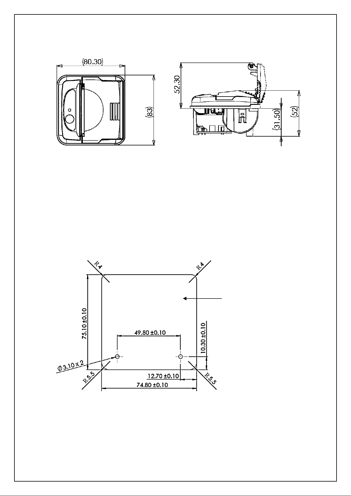
9UNIT DIMENSIONS.................................................................................................................... 9
10 MECHANICAL FIXINGS......................................................................................................... 9
10.1 BACK FIXING ......................................................................................................................... 9
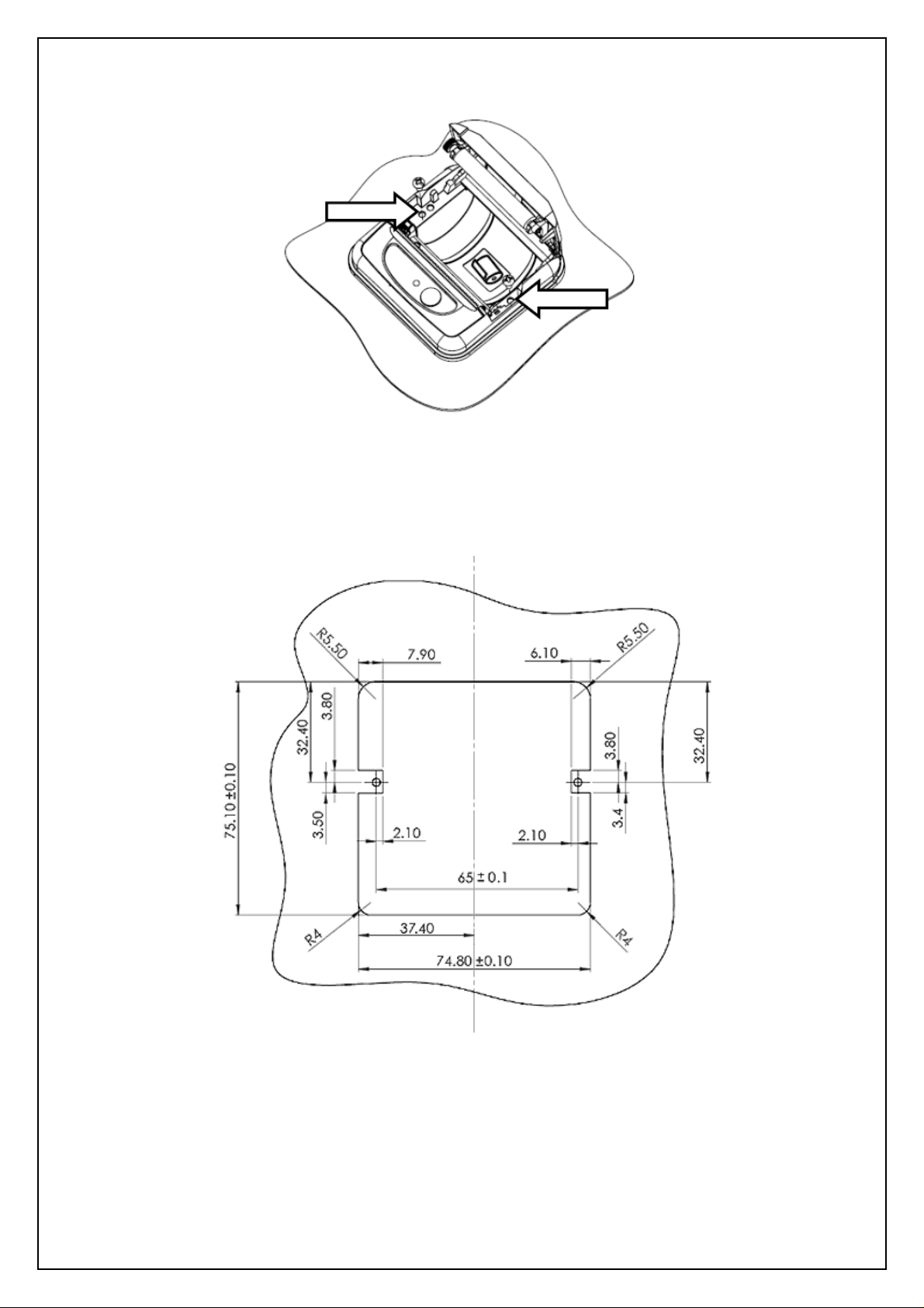
10.2 FRONT FIXING ..................................................................................................................... 10
10.3 MOUNTING BRACKET............................................................................................................ 11
10.4 FIXING ORIENTATIONS .......................................................................................................... 11
10.5 LOCATING THE PRINTER ....................................................................................................... 11
11 MODES OF OPERATION..................................................................................................... 12
11.1 IDLE MODE.......................................................................................................................... 12
11.2 SPOOL MODE...................................................................................................................... 12
12 PAPER................................................................................................................................. 13
12.1 LOADING PAPER .................................................................................................................. 13
12.2 PAPER OUT AND HEAD UP SENSORS..................................................................................... 13
13 LED INDICATIONS............................................................................................................... 14
14 PRINTER OPERATION AND PROGRAMMING.................................................................... 15
14.1 DATA BUFFER ..................................................................................................................... 15
14.2 SPOOL MODE...................................................................................................................... 15
14.3 CHARACTER PRINTING AND FONTS ........................................................................................ 15
14.4 GRAPHICS PRINTING AND OTHER PROGRAMMING MODES ........................................................ 15
15 TECHNICAL SUPPORT ....................................................................................................... 16

Ap1400 Installers’ Guide Page 3 of 16
2 REVISION HISTORY
Version Date Description
1.0 08/01/13 First Release
1.1 28/01/13 Second release, minor revisions
1.2 08/10/13 Third release, minor revisions
3 INTRODUCTION
This document is an Installer Guide, written for the person connecting the Able Systems Ap1400
thermal printer.
Please read this Guide carefully before making any connection.
A separate Programmers Guide provides details of the control codes, and describes the internal
operation of these products.
3.1 NOTES ON PRINTER FIRMWARE REVISIONS (INCLUDING FLASH)
Able Systems reserves the right to modify and improve the firmware in its printer products at any time.
Whilst every effort is made to ensure backward compatibility, no guarantee in this respect is given or
implied.
The Ap1400 includes a flash-reprogramable microcontroller. This allows firmware upgrades under
customer control (including customised fonts, which may be created using the Able Systems Font
Editor Utility). Refer to the factory for more information on this feature, if required.
3.2 COPYRIGHT NOTICE AND DISCLAIMER
Copyright subsists in all Able Systems intellectual property, including controller firmware (embedded
software) and circuit diagrams, pin connection lists and application data. No warranty in respect of
patent rights of Able Systems Limited or of third parties is given. Unauthorised reproduction or
amendment of controller firmware may result in prosecution.
Design Registration of the Ap1400 range of printers has been applied for.
Fujitsu is a registered mark of its owner Fujitsu Limited. References to this or other owners' marks in
this document are for illustrative purposes only.
Able Systems do not assume responsibility for interchangeable functionality of other parties'
command sets.
3.3 IMPORTANT INFORMATION
Standard ESD precautions must be observed when handling,
installing and servicing this product. Failure to do so may
invalidate the warranty.
Keep the unit in the anti-static bag until you are ready to
install it.
Use an earthed wrist-strap when handling.
NOTE: The Ap1400
is a component: compliance to all applicable
national and international regulations remains the responsibility of
the system integrator.
Check connections to the host equipment are wired correctly before
connecting to Ap1400. Failure to do so may damage the Ap1400
and/or host.

Ap1400 Installers’ Guide Page 4 of 16
4 EMC STATEMENT AND CAUTION
The European Union (EU) has introduced laws covering Electro-Magnetic Compatibility
(EMC). This section defines our current view of this law, as it relates to the Ap1400.
Able Systems believes that the Ap1400 is exempt from this law because:
It is a component, designed for building into other products
Responsibility for EMC compliance rests with the System Integrator.
To aid system integrators, ABLE Systems has carried out fully traceable EMC
testing and a copy of a test certificate can be provided on request. To ensure compliance with this
testing, the system integrator should ensure that there is a sound earth connection to the earth
strap, and the data and power connections are enclosed by the equipment they are
mounted in and are no more than 3m long.
5 ORDERING PART CODES, OPTIONS AND ACCESSORIES
The following table details full Able Systems part codes for products related to the Ap1400 printer:
DATA CABLES
AP1400SC Ap1400 Serial Cable Assembly (unterminated)
AP1400D9 Ap1400 Serial Cable Assembly D9F
AP1400USBC Ap1400 USB-A to Mini-B Cable 1m
MOUNTING BRACKETS
Ap1400MBKIT Ap1400 Mounting Bracket (including fixings)
POWER CABLES & ADAPTORS
Ap1400PSA Universal Power Supply Adaptor supplied with UK, Euro,
USA and Australian style click-ins 100-240Vac
Ap1400PC Ap1400 Power Cable Assembly (unterminated)
SOFTWARE
Ap1400FEU Able Font Editor Utility (for Windows)
Ap1400SU Able Printer Setup Utility
Multiple Windows drivers
CONSUMABLES
A05836TPR1 36mm Diameter thermal paper (approx. 13m long)
A05836RLRKIT 36mm Diameter linerless label thermal paper
(18rolls+cleaning card)

Ap1400 Installers’ Guide Page 5 of 16
6 INTERFACE DETAILS
6.1 RS-232 SERIAL INTERFACE
The Ap1400 printer has an industry standard RS-232 interface. The default parameters are 9600
baud, 8 data bits, 1 stop bit and no parity. Other baud rates can be programmed by control codes, or
by using a setup utility available from the factory. The following baud rates are supported: 1200, 2400,
4800, 9600, 19200, 38400, 57600 and 115200 baud.
Serial data is expected in standard RS-232C format with -12V meaning 'mark' or '1' and +12V a
logical '0', with reference to the common ground. The serial data output line, TxD, transmits
XON/XOFF and status information to the host at the same Baud rate and in the same format as the
serial data input. The hardware busy line is true (nominal -12V) when busy. Both serial output lines
will relax to approximately 0V when the Ap1400 is off, and the user must allow a short period after
switching on before relying on the values of these signals.
Some host equipment use a constant space condition (+12V) to indicate a reset condition or wait
state. Some battery powered host equipment present the same output signal when they go to sleep.
The Ap1400 can be set to ignore this condition as detailed in the Programmer’s Guide, but even then
this type of host behaviour may result in one or more spurious characters being received and printed.
6.2 USB INTERFACE
The Ap1400 has a full speed USB 2.0 client interface allowing the unit to be connected to aWindows
based host via USB allowing simple configuration and access. There are two ways of printing from the
Ap1400;
1) Spool printing. This is the way a ‘standard’ desktop printer works and will enable you to print
in the normal way from applications such as Word, Excel or any other application that
supports spool printing. Spool printing requires the installation of windows drivers and allows
all applications access to the printer.
2) API interface. The API interface is for programmers who wish to add USB printing to their
programs. This interface gives exclusive control of the printer and allows either text or
graphical printing. In addition, the full printer command set is available to the programmer
allowing much tighter tailoring of the printed output to suit this form of printer & application
combination.
Please contact Able Systems if you require the USB drivers or API interface.

Ap1400 Installers’ Guide Page 6 of 16
7 POWER SUPPLY DETAILS
The Ap1400 is powered via the connector, J3. A suitable ‘Universal’ input mains power supply is
available from Able Systems and can be ordered using the part number; Ap1400PSA. It is supplied
with UK, Euro, USA & Australian style click-ins and needs a 100-240VAC input. When ordering the
Ap1400PSA you will receive both the wall adapter and the Ap1400 conversion cable, both shown
below.
Alternatively, the user may make their own power supply arrangements as described below.
7.1 ALTERNATIVE POWER SUPPLY ARRANGEMENTS
The Ap1400 is designed to be operated from a 4.5V to 8.5V voltage source which is capable of
supplying the primary power for the printer. The electrical specification for the power supply input of
the Ap1400 printer is:
Input Voltage Range: +4.5V to +8.5V (without any internal voltage or reversal protection)
Supply Current Requirement: 100mA ( Printer in Idle Mode )
( typical ) 3A average ( Printer Printing )
10A peak ( Printer Printing )
N.B. The average and peak current requirements can be adjusted by firmware control codes.
See the Programmer Guide or contact Able Systems for details.
The recommended power supply input is 7.5V with a current capacity of at least 3.3A, and this allows
the printer to perform best. However, the printer will automatically accommodate any input voltage in
the range 4.5V to 8.5V by varying the print speed accordingly. In addition, power supplies with lower
current capacities may be accommodated by varying the internal PowerSave parameter. See the
Programmers Guide or contact the factory for more details.
N.B. No internal regulation or protection is included inside the printer, so the user must ensure
that the printer cannot be damaged by connecting an inappropriate power supply.

Ap1400 Installers’ Guide Page 7 of 16
8 CONNECTION GUIDE
The Ap1400 is fully hot-swappable. It has 3 user connectors and a chassis earth strap. Either data
connector may be used, but only one concurrently. The Ap1400 will detect and receive data from a
single data connector automatically. To swap data connections, the power must be cycled.
8.1 J4 – RS232 DATA
J4 Mating Connector
Manufacturer
: Molex
Part Number
:
51065
-
0500
Crimp Part Number
: 0502128000
Pin
Ap1400 Function
Ap1400 Input/Output
Standard PC D9 Pin
1
RX
data
i/p
3
2
Printer Wake
i/p
4
3
Printer Busy
o/p
6 and 8
4
TX
data
o/p
2
5
GND
-
5
A moulded RS232 D9 lead for direct connection to a PC RS232 port can be obtained from Able by
ordering part number: Ap1400D9.
An unterminated RS232 lead can be obtained from Able by ordering part number: Ap1400SC.
J3 Power
(pin 1 indicated) J2
USB
Data
J4 RS232
Data
(pin 1 indicated)
Chassis
Earth Strap

Ap1400 Installers’ Guide Page 8 of 16
8.2 J3 – POWER
J3 Mating Connector:
Manufacturer
: JST
Part Number
:
XHP
-
4
Crimp Part Number
: SXH
-
002T
-
P0.6
Pin
Signal
Description
1
V+
4.5V
-
8.5V dc positive supply to printer.
6A Fuse Required*
(Connect to both V+ pins to avoid overloading connector J3)
2
V+
3
GND
0V Co
mmon (signal and power ground).
(Connect to both GND pins to avoid overloading connector J3)
4
GND
*NOTE: A
n unterminated
cable assembly is available from Able
Systems, part number Ap1400PC. An in-line 6A fuse is required in
the V+ line. Failure to fit this may invalidate the warranty. Please
follow the wiring diagram below:
8.3 J2 – USB DATA
The Ap1400 supports full speed USB 2.0 connections to the Mini USB-B port, J2. A standard USB-A
to Mini USB-B lead can be obtained from Able by ordering part number: Ap1400USBC.
Note: Power must also be provided at J3 to enable printing.
Please contact Able systems for USB drivers.
J2 Mating Connector
Standard Mini USB-B (USB 2.0).
8.4 CHASSIS EARTH STRAP
The earth strap is provided as an electrostatic discharge path from the printer mechanism to the
system ground. In earthed equipment, the eyelet should be connected to ground. It is designed to
accommodate a No.2 screw.
NOTE: If the Ap1400 is being fitted into host equipment that has no
earth, remove the earth strap with wire-cutters to prevent short
circuits to the printer and/or host equipment.

Ap1400 Installers’ Guide Page 9 of 16
9 UNIT DIMENSIONS (All dimensions in mm)
10 MECHANICAL FIXINGS
The Ap1400 has several fixing options to suit a variety of installations;
10.1 BACK FIXING
1) Prepare the panel aperture as described below.
2) Fit the printer into the panel using M3 machine screws being careful not to screw more than 5mm
in to the Ap1400.
3) Open the lid of the printer, fit a paper roll and close the lid.
4) Connect power and data leads as described in the ‘Connection Guide’ in this document.
Panel aperture as
viewed from
rear

Ap1400 Installers’ Guide Page 10 of 16
10.2 FRONT FIXING
1) Open the lid of the printer and remove the two knock-outs using a small flat-headed screwdriver.
2) Prepare the panel aperture as described below.
3) Fit the printer to the panel and fix in place using two self-tapping screws as shown above (Ø 3mm
max, included in Ap1400KIT).
4) Fit a paper roll and close the lid, checking the screw heads clear the lid.
5) Connect power and data leads as described in the ‘Connection Guide’ in this document.

Ap1400 Installers’ Guide Page 11 of 16
10.3 MOUNTING BRACKET
1) Fit the printer into the panel and apply the mounting bracket as shown below.
2) Secure with two M3 machine screws or two cable ties, one at either side of the bracket. (all
included in Ap1400KIT).
3) Open the lid of the printer, fit a paper roll and close the lid.
4) Connect power and data leads as described in the ‘Connection Guide’ in this document.
10.4 FIXING ORIENTATIONS
Ideally, the fixing orientation of the Ap1400 host panel should permit the free rotation of the paper roll
in normal operation and its retention when the paper compartment is opened. The printer can
therefore be mounted horizontally or angled to the limits shown below.
Should you wish to use the Ap1400 in orientations that exceed these limits please contact Able
Systems for advice.
10.5 LOCATING THE PRINTER
NOTE: The Ap1400 is a thermal printer and care should be taken to
ensure that the printer and the paper it prints to are not subjected to
extreme temperature or humidity
NOTE: The Ap1400 is an open
-
framed printer. It is the installer’s
responsibility to ensure the enclosure into which the printer will be
fitted confers suitable protection from environmental factors and
electrical and physical interference, as well as preventing user
access behind the face of the panel.

Ap1400 Installers’ Guide Page 12 of 16
11 MODES OF OPERATION
The Ap1400 has two operating modes, when not actually printing:
"Idle Mode": ready to accept data, but no data are in the buffer awaiting printing, and the
printer motor is not running;
"Spool Mode": active, but storing data for later printing.
Modes are indicated by different colour combinations on the front-panel LED (see section 8).
11.1 IDLE MODE
In idle mode, the printer is ready to receive data, which will be printed as soon as complete lines or
graphics patterns are decoded. It responds to the paper feed button in the normal way, and can also
produce a demonstration print (see below).
11.2 SPOOL MODE
In spool mode, data is received and stored, but not printed. This is useful when printing needs to be
suppressed during data transfer (for example in mobile radio systems); or when the printer is unable
to print because the paper has run out or the lid is open.
The Ap1400 will automatically enter spool mode when the paper is out, when the head is up, or if
some other error condition occurs, or alternatively by command from the host. Spool mode may be
cleared by host command, automatically when the condition is cleared, or by "double-clicking" the
feed button.

Ap1400 Installers’ Guide Page 13 of 16
12 PAPER
Pressing the paper feed button when the printer is idle, or in spool mode, advances paper at typically
60 mm per second. However, the feed button has additional functions:
"Double-clicking" the button: (i.e. pressing and releasing twice in quick succession just like a PC mouse)
in idle mode, prints a demo/test message including the firmware version, encoded
calibration data, and the full character set;
in spool mode, or having been out of paper, prints any stored data and enters idle mode.
Some of the functions of the paper feed button can be invoked or disabled under control of the host.
12.1 LOADING PAPER
The procedure for loading paper is as follows:
1. Press the lid in towards the panel.
2. Unwind a small amount of paper from the roll and Insert the Paper Roll into the Printer.
3. Close the Lid, and the paper is loaded.
4. After loading, check that the paper is straight and advances properly, and tear off any excess
by pulling the paper sharply towards you across the serrated tear bar. In the event of a jam or
other paper loading problem, release the lid and straighten the paper before closing again.
Paper rolls must be 57.5 ± 0.5 mm wide, 36 mm maximum diameter, and have the thermally sensitive
coating on the outside. The printer can accept rolls which are coreless or wound on a core. Suitable
rolls are available as ASL Product Code:
A05836TPR1 Thermal Paper Roll (36 mm dia, 13.5 m long approx)
12.2 PAPER OUT AND HEAD UP SENSORS
A reflective optical Paper Out sensor within the mechanism detects an out-of-paper condition, and/or
senses black marks to register with pre-printed forms. A mechanical Head Up sensor detects when
the lid is open.
By default, the printer enters Spool mode automatically if either sensor becomes active. The printer
will automatically exit spool mode, and print any stored data, when new paper is loaded and the lid
closed. This behaviour may be modified. Please refer to the Programmers’ Guide for details of how to
configure these functions.

Ap1400 Installers’ Guide Page 14 of 16
13 LED INDICATIONS
The LED indicator at the front of the Ap1400 has a number of colour combinations, which repeat in up
to a 4-phase pattern to provide status information (see table below).
In summary, if the LED is constant green it indicates that the printer is operating normally. Flashing
on and off indicates that Spool mode is active and no printing can take place. Red warns of a low
power supply voltage or other problem. No light indicates that the unit is off.
LED Pattern Table
Pattern
Power Status
Buffer Mode
Constant Green
OK
Normal
Fast Flashing Green
OK
Spool *
Long Green
-
Short Red
Low Voltage
Normal
Short Green
-
Short Red
Low Voltage
Spool *
Fast
Flashing Red
Error Condition
Spool (Printing prohibited)
No light
Printer is off
* (Spool may have resulted from Paper Out or Head Up conditions)
Although this table may seem complicated, few applications will produce many of the combinations.
Other LED Patterns
Other LED patterns may be programmed into the Ap1400 on request or by the system designer.
Please refer to the Programmers’ Guide for details of how to configure these functions.

Ap1400 Installers’ Guide Page 15 of 16
14 PRINTER OPERATION AND PROGRAMMING
The Ap1400 utilises a Fujitsu FTP-628MCL103 printer mechanism, with a fixed (parallel) print head
with 384 horizontally-arranged thermal elements. The paper is advanced by a stepper motor, and
printing takes place in a single dot row for each step of the paper. Each printed dot is approximately
1/8 mm square. The printing speed and dot density are controlled according to the power supply
voltage and the head temperature.
Various printing modes, including graphics, are invoked by 'Escape' sequences. Control codes and
status report protocols are described in detail in the Programmers' Guide, available separately.
14.1 DATA BUFFER
The Ap1400 has a nominal 10k byte buffer to optimise throughput: this enables data to be received
into the buffer while previous lines are being printed. Printing will be initiated on receipt of a valid
logical line of data or a complete graphics pattern.
The buffer may be cleared by data command or by a hardware reset. A partially full line will be
printed on receipt of an appropriate control code, or after a programmable timeout delay.
14.2 SPOOL MODE
Spool mode is can be entered by:
a command from the host;
Paper Out condition or Head Up condition being sensed;
an error condition (e.g. head over temperature, power supply over voltage, etc).
In spool mode, the buffered data are stored without being printed until the mode is exited by:
a command from the host;
the 'causing condition' (e.g. Paper Out or Head Up) being cleared;
the paper feed button being double-clicked.
14.3 CHARACTER PRINTING AND FONTS
The default 32-column character set is formed from a 24x10 dot matrix, and is based on the industry
standard IBM® character set Code Page 437. This character set has been modified to include the
Euro symbol (‘€’) at position 80H (128 Decimal), in place of the usual capital C with cedilla (‘Ç’).
Various combinations of single or double width, single or double height, inverted, underlined, and
other attributes may be mixed within a line.
Customised fonts may be created using the Able Systems Font Editor Utility, and downloaded to the
Ap1400. Please contact the factory for more information.
14.4 GRAPHICS PRINTING AND OTHER PROGRAMMING MODES
Various dot-addressable graphics modes are supported, at up to 384 dots per line. TheWindows
driver operates in the graphics mode. Refer to the Programmer’s Guide for full details of this and other
advanced programming modes.

Ap1400 Installers’ Guide Page 16 of 16
15 TECHNICAL SUPPORT
In the meantime, if more information is required, please contact;
Technical Support: (Support@Able-Systems.com)
Or call +44 (0) 1606 48621 and select option 4 for Technical Support.
[End]
Copyright © Able Systems Limited 2013. All Rights Reserved
Other manuals for Ap1400
1
Table of contents
Other ABLE Printer manuals
Popular Printer manuals by other brands

Samsung
Samsung CLP 610ND - Color Laser Printer Service manual

IBM
IBM InfoPrint 20 Quick reference card

Samsung
Samsung CLP-315 - CLP 315 Color Laser Printer manual

Canon
Canon PIXMA E3300 Series Getting started

Konica Minolta
Konica Minolta magicolor 7450 installation guide

Brother
Brother MFC MFC-5440CN user guide