ABLE Ap25 User manual

The Experts in Small Printer Solutions
User Guide
Ap25
Able Systems Limited Denton Drive, Northwich, Cheshire CW9 7TU England
Tel: +44 (0) 1606 48621 Fax: +44 (0) 1606 44903 Web: www.able-systems.com

Able Systems Limited
Northwich, Cheshire, England
www.able-systems.com
USERS' GUIDE
to the
ABLE SYSTEMS Ap25-24, Ap25-32 & Ap25-40
Panel Mounting Printers
(with Serial and Parallel TTL Interface)
Contents 1 Introduction
2 On-line Information
3 Pin Connections
4 Installation
5 Operation and Programming
1 INTRODUCTION
This document is a Users' Guide, written for the person designing-in, connecting and using the Able
Systems Ap25 panel mount mini printer. Please read it carefully before making any connection.
There are three versions available (each fitted with different printer mechanisms), the Ap25-24 (fitted
with the M-160, 24 characters per line), the Ap25-32 (fitted with the M-163, 32 characters per line) and
the Ap25-40 (fitted with the M164, 40 characters per line).
2 ON-LINE INFORMATION
Able Systems maintains a site on the World Wide Web. This will include application data updates,
product announcements, and e-mail facilities for customer support.
The URL of our web site is: http://www.able-systems.com
COPYRIGHT NOTICE and DISCLAIMER
Note that copyright subsists in all Able Systems intellectual property, including controller firmware (embedded software) and
circuit diagrams, pin connection lists and application data. No warranty in respect of patent rights of Able Systems Limited or
of third parties is given. Unauthorised reproduction or amendment of controller firmware may result in prosecution.
Note: EPSON is a registered mark of its owner Seiko Epson Corporation. References to this or other owners' marks in this
document are for illustrative purposes only.
Copyright © Able Systems Limited 2005 All Rights Reserved Ap25ug2_1.pdf // 23/08/05, 12:02//IKE

3 PIN CONNECTIONS
The Ap25 has three external connectors or connection areas, for data and power, auxiliary power, and
the printer mechanism. There are also some onboard jumpers. Please refer to the layout diagram for
connector locations and pin orientation.
3.1 Data/Power Connector J3
Function J3 Pin no Function
Data Input D7 1 2 Busy output (high when busy)
(or Serial/Parallel mode select)
Data Input D6 3 4 Inverted Mode Select Input
(or Baud Rate Select in serial mode) (low for inverted/reversed/data mode)
Data Input D5 5 6 Ground (0V)
(or Baud Rate Select in serial mode)
Data Input D4 7 8 Ground (0V)
Data Input D3 9 10 Power for mechanism (+5V)
Data Input D2 11 12 Power for logic (+5V)
Data Input D1 13 14 Reset Input (low to reset)
Data Input D0 15 16 Serial Data / Parallel Data Strobe Input
3.2 Auxiliary Power Connector J4
These connections are in parallel with those on J3, and are provided for cases in which the user
prefers to separate the data and power connectors, as we would recommend.
J4 Pin no Function
1 Power for logic (+5V)
2 Power for mechanism (+5V)
3 Ground (0V)
3.3 Paper Take-up Motor Connector J5 (only fitted to customer order)
J5 Pin no Function
1 Ground (0V)
2 Paper Take-up Motor +ve
The output from Pin 2 is in parallel with the mechanism motor drive, with a protective series resistance
of about 16 Ohms. Please consult the factory before making any connection.
4 INSTALLATION
4.1 Power Supply
A clean DC power supply of 5V ±5% 3A is required to power the Ap25. The rise time of the supply
must be short enough to give a valid reset signal to the controller chip. It is recommended that the
power supply for the controller circuits is separate from the supply to the mechanism motor and
solenoid circuits, to minimise interference.
In the event that the power supply is not adequate to power the Ap25, on board Circuitry will hold the
printer in reset and avoid any damage which may occur to the printer mechanism.
Ap25 Users’ Guide Page 2 of 8

4.2 Parallel and Serial Interface Selection
Serial and parallel data modes are selected using D7 (pin 1 on J3):
Parallel mode is selected if D7 is held low (connected to 0V) for a period of 100ms after the
printer is reset.
Serial mode is selected if D7 is held high or left unconnected (internal pull-up to +5V) for a
period of 100ms after the printer is reset.
In “classic” mode, the parallel interface is selected by having D7 low (logic “0”) at power up. In some
parallel applications the port driving this pin may be indeterminate at power up and so an alternative
parallel select is provided (internal jumpers S5/S6) factory set. If either of the two serial/parallel select
pins are held to ground on start up, then parallel mode is selected. Both pins must be left high to
select serial data. In order to change from serial to parallel, or from parallel to serial, the printer must
be reset.
Serial data Baud rates are selected on D5 and D6 when the printer is in serial mode.
Serial data Baud rates:
0101D6 01
10D5 9,6002,4001,200300Baud
Note that the combination for 9600 Baud was used to select 110 Baud in the Ap24 family (110 Baud
is not available in the Ap25). In order to implement the baud rate the printer must be reset.
4.3 EMC Compliance
As a component, the Ap25 is outside the scope of the EMC Directive and the user must take
responsibility for the compliance of the complete equipment or installation.
5 OPERATION and PROGRAMMING
5.1 Parallel Data Mode
D7 to D0 are the data connections for parallel mode 8 bit data. If using one of the backwards
compatible 7 bit character sets (Ap24 family) D6 to D0 are the data connections. Positive true ASCII
Fig. 5.1 Parallel Connection to a PC
Ap25 Users’ Guide Page 3 of 8
Printer J3
2
4
5
6
8
PC Parallel Port
1
2
3
7
15
1
2
3
4
5
6
7
8
9
10
11
12
13
14
15
16
18
10 / 11
19 / 12
NC
NC
NC
D7
D6
D5
D4
D3
D2
D1
D0
Busy
Invert
GND
GND
VCC
Reset
Strobe
Mech
Strobe
D0
D1
D2
D3
D4
D5
D6
GND
Ack / Busy
Paper end / GND
Error

codes are accepted at TTL or 5V CMOS levels. The data inputs are not latched and must be static
during the handshake sequence. The Data Strobe input times the incoming data transfer. When the
printer is not busy (the busy signal is low) the data must be held static on the data pins and the strobe
signal taken low until the busy signal goes high to acknowledge the data transfer. The data strobe
must then be taken high ready to transmit the next byte. Figure 5.1 shows typical connections to a PC
parallel port.
5.2 Serial Data Mode
The serial data input accepts a TTL or 5V CMOS positive true signal. The busy signal will be low
when the printer is ready to accept data. The Ap25 is not suitable for direct connection to a PC RS232
Com. port. (Please refer to ASL for a converter board, or alternatively Able Systems produce an
Ap25S which is the serial RS232 version of the Ap25 and is suitable for direct connection to a PC.)
Figure 5.2 shows typical connections to a PC serial com. port for the Ap25.
Fig. 5.2 Serial Connection to a PC
5.3 Busy Output Signal
The controller asserts the Busy output when the input buffer is one character away from being full.
The following character will, however, be loaded into the input buffer. This avoids any data being lost
due to the host not responding to the busy signal immediately (such as with a double-bufferedUART
in a PC).
5.4 Printing modes and data buffer
Character printing modes include graphics, inverted, double height and double width. Graphics mode
is cancelled at the end of every dot line, whereas the combinations of double height and width remain
in force until cancelled by a new command.
The Ap25 will print data before the ESCape code and then implement the new mode selection. The
data buffer accommodates 48 bytes, which can extend over many physical print lines, depending on
the mechanism in use and the data format; and new data can be entering the buffer as previous data
are being printed.
5.5 Character Printing
The Ap25 prints the characters from left to right. The characters fit into a 6 wide × 10 high matrix.
The standard letter is 5 wide ×7 high, this provides for a one dot space between each character, a dot
Ap25 Users’ Guide Page 4 of 8
Printer J3
1
2
3
4
5
6
7
8
9
10
11
12
13
14
15
16
NC
NC
NC
D7
Busy
Invert
GND
GND
VCC
Reset
Mech
D0
D1
D2
D3
D4
D5
D6
Serial TTL Data
PC Serial Com. Port
NC
Baud Rate Select
Baud Rate Select
NC
NC
NC
NC
NC
RS232 Serial
Busy
GND
RS232 - TTL
Converter
Converter
TTL - RS232
NC
NC
25 Way D-Type
7
2Data Transmit
5

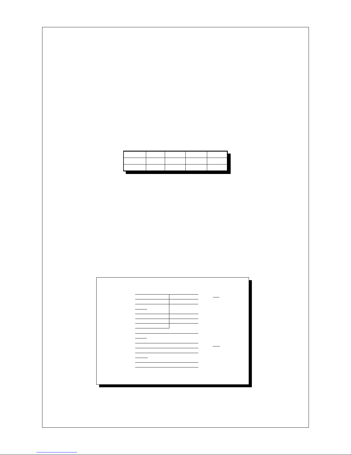
line for descenders and a dot line above and below each character line. The number of characters
required to fill a dot line varies according to the printer, as follows:
0.20mm0.33mm0.4 lines/second40 characters per lineAp25-40 0.25mm0.33mm0.5 lines/second32 characters per lineAp25-32 0.33mm0.33mm0.7 lines/second24 characters per lineAp25-24
Horizontal
dot pitch
Vertical dot
pitch
Lines per secondCharacters per linePrinter
The ASCII characters 32 to 255 (32 to 127 if using a backwards compatible 7 bit character set) are in
the printable range. Any character below character 32 is ignored unless it is one of the control codes
(section 5.7).
5.6 Graphics Printing
The product is programmed to take advantage of the graphics printing capability of the mechanisms.
Graphics are received as the least significant 6 bits of each byte. In this way the same number of
graphics bytes are required to terminate a line as the number of characters required to print a
complete line. The graphics mode is reset at the end of every dot line and hence the graphics
command, <ESC><02>, must be entered at the start of every dot line.Graphics patterns are built up
as a succession of dot lines across the paper. The number of bytes required to fill a dot line for each
mechanism are the same as the number of characters required to fill a dot line. Large areas of solid
dots are not recommended as they may cause over heating and shorten the ribbon life. Heavy
graphics printing may also require a higher current power supply.
A typical graphics line for the Ap25 would be:
Control code Data (24 bytes for the Ap25-24)
<ESC><02> <00><00><01><02><03><04><05> etc.
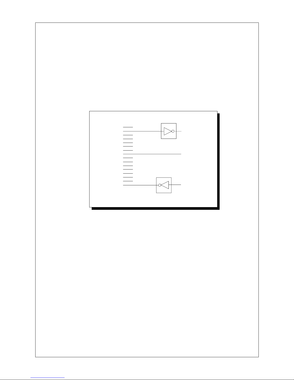
5.7 Control Codes
9 character sets which may be selected for backwards compatibility. The default character set is the
8 bit IBM 224-character set.
Previous versions of the Ap24 family have been supplied programmed with 7 bit character sets, UK,
French, German, “Scandinavian”, Danish/Norwegian, Swedish, Japanese and Spanish character
variations (often to special order). The Ap25 contains all these variants, which are software selected
for backwards compatibility. 8 bit data is selected when using the 8 bit IBM character set, otherwise
the 8th data bit is ignored.
The structure of the command is as follows:
<ESC><127><n> where n is a byte of the form [X,X,X,X,B3,B2,B1,B0] (X = don’t care)
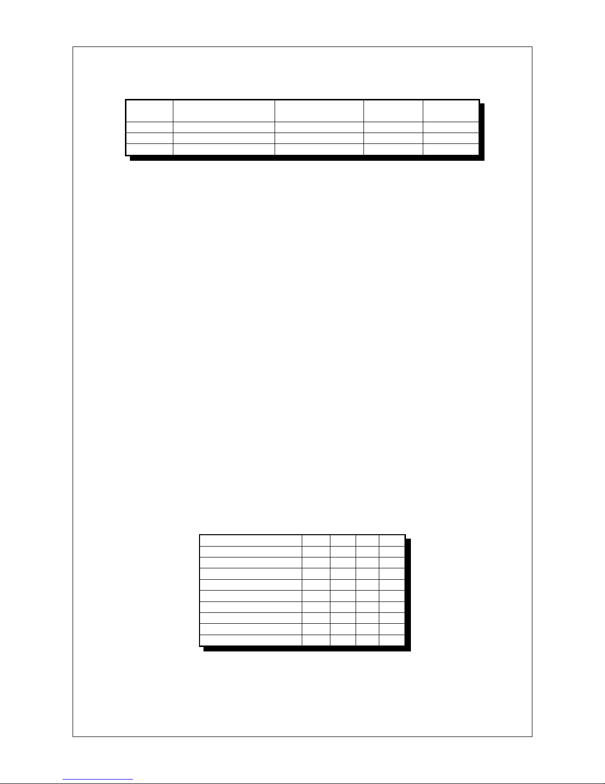
Country selection:
0001Spanish 1110Japanese 0110Swedish 1010Danish 0010Scandinavian 1100German 0100French 1000UK 0000Full 8 bit IBM (default) B0B1B2B3Character set
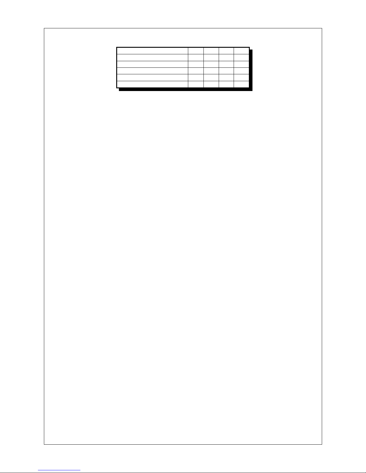
<ESC><n> (If buffer is not empty, print buffer contents and) Set print mode:.
Note: nis a byte of the form [ 0,0,0,0,B3,B2,B1,B0] (all except the lower 4 bits must be zero, to avoid
conflict with other ESCape codes).
Ap25 Users’ Guide Page 5 of 8

Mode selection:
XXX1Double height mode XX1XDouble width mode X1XXGraphics mode 1XXXInverted (reversed) 0000Default B0B1B2B3Print Mode
Any combination of modes is permissible.
The command <ESC><126> stores the current character set and print mode (double height, etc) in
the EEPROM and these will be the default setting the next time the printer is powered on or reset. If
this code is not received the Ap25 reverts to previous default values on the next power up.
<ESC><ESC> (Print any buffer contents, and) Print Self test message.
<ESC><127><n> (Print any buffer contents, and) Select country character set.
<ESC><126> (Print any buffer contents, and) Store country character set and print mode
in EEPROM.
<ESC><125> (Print any buffer contents, and) Clear the EEPROM.
<CR> Print any buffer contents (line terminator). Treat as <CR><LF>.
<LF> Print any buffer contents (line terminator). Treat as <CR><LF>.
<CR><LF> Print any buffer contents (line terminator). Treat as single <CR><LF>.
<LF><CR> Print any buffer contents (line terminator). Treat as single <CR><LF>.
A character line is automatically terminated and printed if it reaches the full line width for a given
mechanism and print mode setting. Note that if any of the above 4 line terminator codes is received
immediately after a character which completes a printable line, it will be ignored.
This treatment differs from the Ap24 family but will generally be an improvement.
<VTAB> Print any buffer contents, and feed 30 dot lines.
If the print quality deteriorates due to dot lines being displaced, theEEPROM can be cleared and the
chip forced to repeat the first-time initialisation by sending the code <ESC><125>.
/Attachment: Appendix 1(EMC Directive 89/336/EC Disclaimer)
(Operator information)
(Ap25 Dimensions)
Ap25 Users’ Guide Page 6 of 8

EMC Directive 89/336/EC (Disclaimer)
Please note that the item to which the enclosed application data refer is designed to be used as a
component in another finished good, and is not intended to be placed on the market or brought into
service independently. The system integrator using this item must assume responsibility for
Electro-Magnetic Compatibility (EMC) between this item and its environment, both for emissions and
immunity/susceptibility.
Particular attention should be paid to the wiring connections between the item and the power supply,
data source and other parts of the user's system in case special shielding and/or cable layout is
required to meet applicable EMC criteria.
Ap25 Series Panel-Mounting Printers
To assist OEM customers, we have carried out traceable pre-compliance tests on our most
popular Ap24 printer (predecessor to the Ap25), which indicate that the printer itself is unlikely to
prevent EMC compliance of the customer's equipment, as follows:
Since the Ap25 is DC powered and will only be electrically connected within an OEM equipment,
conducted emissions and immunity are not relevant, and we consider that the Ap25 falls outside
the scope of the Regulations in these regards.
When fitted in an earthed steel case and connected to an internal data source and power supply,
the Ap25 may be expected to comply with the requirements of the EMC Directive in respect of
radiated emissions and immunity;
When fitted with an earthing wire to the mechanism, the Ap25 may also be expected to comply
with the requirements in respect of electrostatic discharge (ESD).
Earth Connection and EMC Screening Sleeve
Able Systems Ap25 Series printers are fitted with an earthing wire attached to the metal chassis of the
printer mechanism. The other end of the wire will be supplied attached to the panel clamp by an
eyelet. Users are recommended to make a sound earth connection to this point, so that the metal
parts of the printer are electrically bonded to the earthed parts of the user's equipment.
A steel enclosure (Ap25 EMC Sleeve) for the rear of the Ap25 Series, which replaces the panel clamp,
is available to provide additional EMC screening if required.
EMCDISC6.wps (C) ASL January 1996
Ap25 Users’ Guide Page 7 of 8

ABLE Systems Limited Ap25 – p. 8
Dimensions & Connectorsa
Tél. : (0)1 34 Ap25 User guide Page 8of 8
DIMENSIONS
2
1
J5
J4
3
J3
15
1
1
Enrouleur optionnel
Alimentations
SERIE et PARALLELE
en niveaux TTL ou 5V CMOS
109mm 87mm
113.5mm 96mm
Panel Cut Out
Allow 6mm
for panel clamp
62mm
66mm
Door latch
Paper
Feed
Other manuals for Ap25
1
This manual suits for next models
3
Table of contents
Other ABLE Printer manuals