Abloy DA430 Guide
An ASSA ABLOY Group brand
ABLOY®DA430 SWING DOOR OPERATOR
– Installation and commissioning manual

2
APPROVALS / STANDARDS
Electrical safety tested and approved FI, S, N, D
Low Voltage directive 73/23/EEC as amended by the directive 93/68/EEC
EMC directive 89/336/EEC
----------------- THIS MANUAL CONTAINS IMPORTANT SAFETY INSTRUCTIONS -----------------
Warning - IT IS IMPORTANT FOR SAFETY OF PERSONS TO FOLLOW THESE INSTRUCTIONS.
------------------------------------ SAVE THESE INSTRUCTIONS --------------------------------------------
This appliance is not intended for use by persons (including children) with reduced physical,
sensory or mental capabilities, or lack of experience and knowledge, unless they have been
given supervision or instruction concerning use of the appliance by a person responsible for their
safety.
Do not allow children to play with fixed controls.
Frequently examine the installation for imbalance and sings of wear or damage to cables, springs
and mountings. Do not use if repair or adjustment is necessary.
Disconnect the supply when cleaning or other maintenance is being carried out.
Before installing the operator, check that the operator is in good mechanical condition and it
opens and closes properly.
Ensure that entrapment between door and the surroundings is avoided.
Ensure that the operator is suited for installation. Check temperature, humidity, door weights, etc.
restriction in line with specifications applicable in the manual or other Abloy® Oy material.
Note!
Instructions, design specifications and illustrations which are contained in this manual are not
binding. Abloy Oy reserves the right as part of ongoing product development to make changes
without previous notice.
Warning!
Warning!

3
CONTENTS
1 REVISION ................................................................................................. 4
2 CONTENT OF DELIVERY ........................................................................ 5
3 GENERAL INFORMATION ....................................................................... 6
4 OPERATION ............................................................................................. 7
5 MODE SWITCH......................................................................................... 7
6 INSTALLATION......................................................................................... 8
6.1 Installing the operator and the mounting plate DA105.............................................. 9
6.2 Assembly of the operator and standard arm DC190 to the closing side................. 10
6.3 Assembly of the operator and sliding arm DC194 to the closing side..................... 11
6.4 Assembly of the operator and sliding arm DC194 to the opening side ................... 12
7 INTERNAL CONNECTIONS ................................................................... 13
8 COMMISSIONING................................................................................... 14
9 A SAFE DOOR........................................................................................ 16
10 EXTERNAL CONNECTIONS.................................................................. 17
11 CONNECTION EXAMPLES.................................................................... 18
11.1 Safety sensors DA001 and DA002 ....................................................................... 18
11.2 DA061 and DA062 Microwave motion sensor ...................................................... 19
11.3 DA063 Microwave motion sensor ......................................................................... 19
11.4 DA033 Elbow switch ............................................................................................. 20
11.5 DA039 and DA049 rotary switch........................................................................... 20
11.6 Electric locks EL402, EL404, EL502..................................................................... 21
11.7 Motor locks EL490, EL590.................................................................................... 21
11.8 Motor locks EL420, EL520.................................................................................... 22
11.9 Electric lock EL410 ............................................................................................... 22
12 SELF DIAGNOSTICS.............................................................................. 23
13 MAINTENANCE ...................................................................................... 24
14 SPARE PARTS ....................................................................................... 25

4
1 REVISION
Following pages have been revised:
Page Revision
As at 21.09.2009.

5
2 CONTENT OF DELIVERY
DA430 Swing door operator
- screw M6x16, 1 pcs
- spring washer, 4 pcs
- washer 4 pcs
- hex-socket head screw M6x16, 4 pcs
- grooved spindle, 1 pcs
- tension sleeve, 1 pcs
DA105 Mounting plate
- screws 5,5x32, 6 pcs
- ordered separately
DC190 Standard arm
- screw M6x16, 1 pcs
- screws M5x12 Poz 2, 2 pcs
- screws 4,8x32 Poz 2, 2 pcs
- ordered separately
DC194 Sliding arm
- screw M6x16, 1 pcs
- screws M5x40 Poz 2, 2 pcs
- screws 4,8x60 Poz 2, 2 pcs
- ordered separately

6
Technical data
Measures
• (L) 523 x (H) 68 x (W) 80 mm
• weight 3,5 kg
Supply voltage
• 110 - 230 VAC (±15%) 50...60 Hz
• back-up inlet 24 VDC (±15%) 2A
Enclosure class
• IP20
Temperature range
• storage -20...70 °C
• operation 0...40 °C
Interfaces
• power output 24 VDC max 500 mA
• potential free relay output
0.8 A @ 30 VDC resistive load
0.3 A @ 30 VDC inductive load
Features
• Swing door operator for indoor use only.
• Door weight up to 80 kg (standard arm) and 60 kg (sliding arm).
• Low noise.
• Compact design - easy to install.
• Low resistance if manually used.
• Push&Go.
• Adjustable hold open time 0...60 s or sequential use.
• Built in 24 VDC/0.5 A power supply for external devices.
• Secondary DC inlet power back - up (24 VDC 2A).
• Maximum opening angles:
• With standard arm DC190
On the closing side, 100°
• With sliding arm DC194
On the closing side, 90°
On the opening side, 110°
3 GENERAL INFORMATION

7
AUTO
OPEN
MAN
Abloy®DA430 is an electromechanical swing door operator for moderate use.
It can be used on single, internal doors. The Abloy®DA430 has a ”Push&Go”
function. When Push&Go is in operation and door is pushed or pulled manually,
operator opens the door to adjusted opening angle and closes the door after a 5
second of hold open time.
Internal monitoring
Obstructed opening:
The door is set free for 5 seconds and the impulse is restrained during that time.
After that, the operator tries to open the door. If the door is still obstructed in the
same position after 4 trials, operator closes the door.
Obstructed closing:
The door is set free for. After that, new trial is done to close the door. Maximum
amount for trials is 4. If it is exeeded, the door is set free for 1 minute. Atfter this
new trial is done to close the door.
4 OPERATION
5 MODE SWITCH
Note! There is 3 seconds constant delay
when mode switch is changed position
OPEN to AUTO or MANUAL.
The door opens via an impulse and closes after
the adjusted hold open time.
Manual use.
The door opens and stays open.

8
6 INSTALLATION
Steps of installation
- Preparing installation
- Installing the mounting plate if needed
- Mounting the operator and the arm
- Connecting the operator to mains
- Commissioning
- Testing
- Connecting impulse devices
Preparing installation
- Check the correct function
of the door
- Hinges
- Door clearance
- Check the correct function
of the lock
- Lock case
- Striker plate
- Suitability of the
lock’s function
Removal of housing
Note! Remove the protective earth wire from cover and connect it back after
installation.
Ensure the mains disconnected when removing or re-fitting the cover.

9
6.1 Installing the operator and the mounting plate DA105
The operator is installed on the transom, with the mode switch located towards
the hinge side of the door. Securely fix the operator or the mounting plate to the
transom. Minimum requirement for wall profile is 5 mm (steel).
Installing the operator
Installing the mounting plate DA105
The mounting plate DA105 with the door operator ensures the installation base is
level. Use the mounting plate if needed.
0
261
86
15
0
66
55
33
11
522
436
Ø 22
44
210
261,5
399
479
0
44
Hinge line
10
9
10
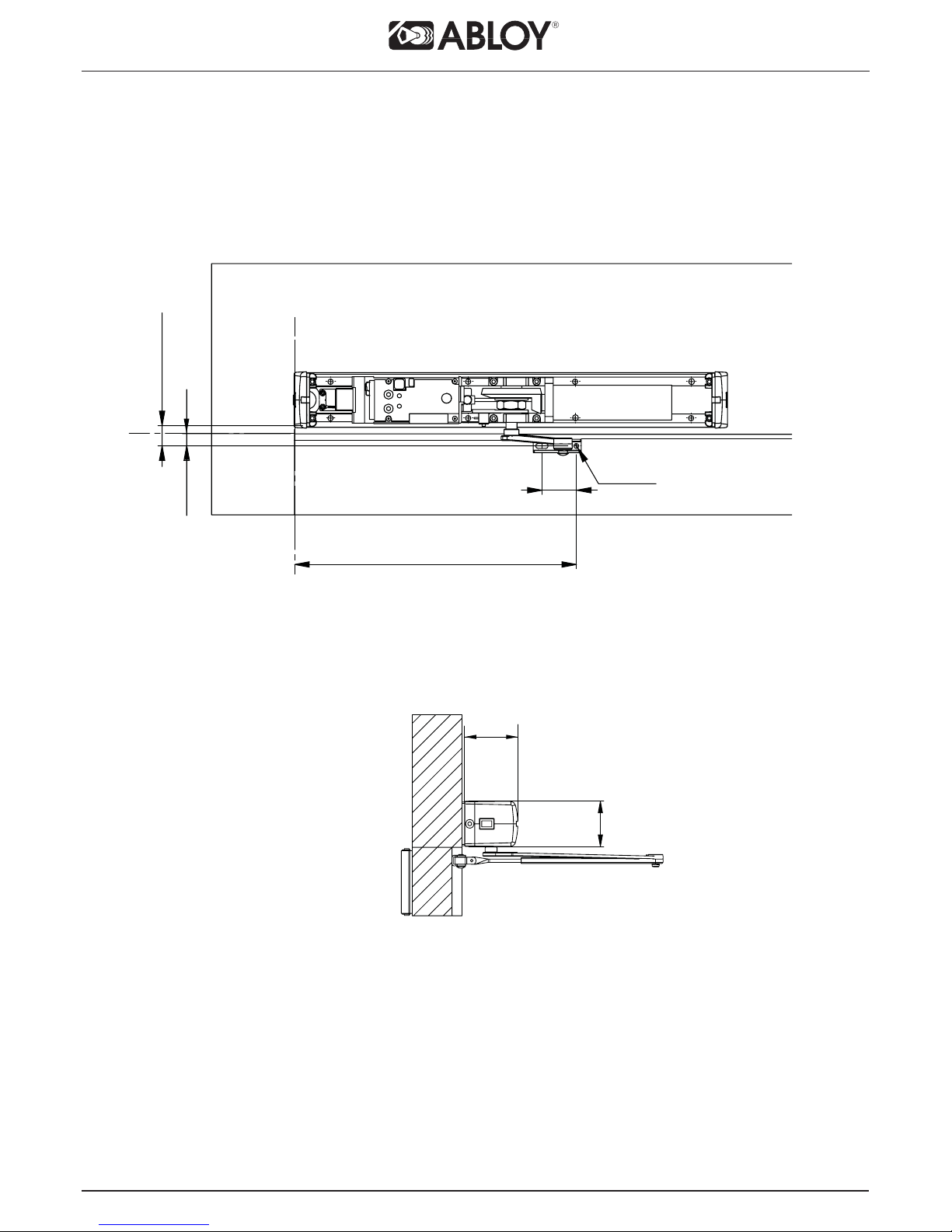
6.2 Assembly of the operator and standard arm DC190 to the
closing side
20**
42
Min. 21*
Max. 32*
340
Ø 6
Hinge line
*The measure from bottom of the operator
** The measure from bottom of the frame
80
68
Table of contents
Other Abloy Door Opening System manuals


Popular Door Opening System manuals by other brands


Normstahl
Normstahl IDO7 installation manual

Häfele
Häfele Finetta T 70 VF manual

AGS
AGS D-PL Instructions for fitting, operating and maintenance

Stanley
Stanley MA900ñ Installation and owner's manual

WITTUR
WITTUR Hydra Plus UD300 Instruction handbook

Alutech
Alutech TR-3019-230E-ICU Assembly and operation manual