Digiway DWPD102S Series User manual

DWPS102S
DWPS102A
DWPS102U
DWPD102SXX
DWPD102AXX
DWPD102UXX
Group Products
DIGIWAY PLUS
Single or double door, inward and outward, automation door
Automatisme pour porte simple ou double, tirante ou poussante
INSTALLATION MANUAL
MANUEL D’INSTALLATION
Range: Door automation / Gamme : Automatismes de portes
EN
G
LI
SH
EN
FRAN
C
AI
S
FR
* Refer to Limited Lifetime Warranty. / Voir conditions de garantie à vie limitée.

DIGIWAY PLUS
INSTALLATION MANUAL EN
General safety precautions
General safety precautions
This manual is intended for professional installers, adequately trained.
This manual is intended for professional installers, adequately trained.
Installation and connections must be carried out in accordance with Good Working Practice and in compliance with the
Installation and connections must be carried out in accordance with Good Working Practice and in compliance with the
current Regulations. Poor installation could be source of a health & safety hazard.
current Regulations. Poor installation could be source of a health & safety hazard.
Read this manual carefully before commencing the installation.
Read this manual carefully before commencing the installation.
First check all of the existing door and frame structure - verify its integrity, stability and strength.
First check all of the existing door and frame structure - verify its integrity, stability and strength.
If necessary modify the structure in order to make it standard, being aware of all the possible
If necessary modify the structure in order to make it standard, being aware of all the possible
problems which could occur during normal use.
problems which could occur during normal use.
Verify that all the zones where there is a risk of crushing, dragging, shearing and other dangers, are protected by electronic
Verify that all the zones where there is a risk of crushing, dragging, shearing and other dangers, are protected by electronic
safety, safety freeboards or barriers.
safety, safety freeboards or barriers.
These devices must be installed in compliance with the current laws and in a perfectly workmanlike way, also in relation to
These devices must be installed in compliance with the current laws and in a perfectly workmanlike way, also in relation to
the place of use, the type of use and the operating logic of the product.
the place of use, the type of use and the operating logic of the product.
The forces developed by the complete system must comply with the current standards and, where this is not possible,
The forces developed by the complete system must comply with the current standards and, where this is not possible,
protect the zones with electronic safety devices.
protect the zones with electronic safety devices.
Apply hazardous area notices required by the applicable regulations.
Apply hazardous area notices required by the applicable regulations.
Before the actuator is connected, make sure that the plate details corresponds to those of the mains power and that there
Before the actuator is connected, make sure that the plate details corresponds to those of the mains power and that there
is a differential circuit-breaker and an adequate protection against overcurrents on the supply side of the system.
is a differential circuit-breaker and an adequate protection against overcurrents on the supply side of the system.
Fit a Dual Pole disconnection switch with contact opening gap of at least of 3 mm.
Fit a Dual Pole disconnection switch with contact opening gap of at least of 3 mm.
Interrupt the power supply before opening the cover of the actuator for any maintenance or repairing intervention.
Interrupt the power supply before opening the cover of the actuator for any maintenance or repairing intervention.
Handling of electronic parts must be carried out wearing grounded antistatic bracelets to avoid any static damage.
Handling of electronic parts must be carried out wearing grounded antistatic bracelets to avoid any static damage.
Servicing the actuator is of fundamental importance if the system is to operate correctly and safely.
Servicing the actuator is of fundamental importance if the system is to operate correctly and safely.
Comply with the manufacturer’s instructions described in this manual.
Comply with the manufacturer’s instructions described in this manual.
Only use genuine spare parts if replacements or repairs are required.
Only use genuine spare parts if replacements or repairs are required.
The motor manufacturer declines any responsability in the event of component parts fitted that are not compatible with the
The motor manufacturer declines any responsability in the event of component parts fitted that are not compatible with the
safe and correct operation.
safe and correct operation.
The actuator must be installed only inside buildings
The actuator must be installed only inside buildings
The manufacturer declines all liability for damage caused by assembly on the outside, without adequate protection.
The manufacturer declines all liability for damage caused by assembly on the outside, without adequate protection.
This product cannot be installed in places with an explosive atmosphere or in the presence of inflammable fumes or
This product cannot be installed in places with an explosive atmosphere or in the presence of inflammable fumes or
gases.
gases.
General safety precautions
General safety precautions
.................................................................................................................................
.................................................................................................................................
2
2
Machinery Directive
Machinery Directive
............................................................................................................................................
............................................................................................................................................
3
3
Instructions of use
Instructions of use
..............................................................................................................................................
..............................................................................................................................................
3
3
Declaration of the Manufacturer
Declaration of the Manufacturer
.........................................................................................................................
.........................................................................................................................
3
3
Identifying product and parts
Identifying product and parts
..............................................................................................................................
..............................................................................................................................
4
4
Accessories
Accessories
.......................................................................................................................................................
.......................................................................................................................................................
5
5
Overall dimensions and mounting guide
Overall dimensions and mounting guide
............................................................................................................
............................................................................................................
6
6
Technical specifications
Technical specifications
......................................................................................................................................
......................................................................................................................................
7
7
Mechanic installation - Sliding arm version
Mechanic installation - Sliding arm version
........................................................................................................
........................................................................................................
8
8
Mechanic installation - Articulated arm version
Mechanic installation - Articulated arm version
..................................................................................................
..................................................................................................
9
9
Wiring diagram and connections
Wiring diagram and connections
........................................................................................................................
........................................................................................................................
11
11
LED messages
LED messages
...................................................................................................................................................
...................................................................................................................................................
12
12
Getting started
Getting started
....................................................................................................................................................
....................................................................................................................................................
12
12
•
•
Step I : Set-up
Step I : Set-up
.............................................................................................................................................
.............................................................................................................................................
13
13
•
•
Step II : Configuration
Step II : Configuration
..................................................................................................................................
..................................................................................................................................
14
14
•
•
Step III : Door calibration
Step III : Door calibration
.............................................................................................................................
.............................................................................................................................
15
15
•
•
Step
Step
IV : Adjustings
IV : Adjustings
......................................................................................................................................
......................................................................................................................................
16
16
•
•
Step
Step
V : Advanced sets
V : Advanced sets
................................................................................................................................
................................................................................................................................
17
17
Disabled persons settings
Disabled persons settings
..................................................................................................................................
..................................................................................................................................
19
19
Radio transmitters management
Radio transmitters management
.......................................................................................................................
.......................................................................................................................
20
20
Reset to factory default & system reset
Reset to factory default & system reset
..............................................................................................................
..............................................................................................................
20
20
Double door installing
Double door installing
.........................................................................................................................................
.........................................................................................................................................
21
21
Warranty
Warranty
............................................................................................................................................................
............................................................................................................................................................
25
25
Summary
Summary
pag.
pag.
2cdvi.com
cdvigroup.com

INSTALLATION MANUAL
DIGIWAY PLUS
3
cdvi.com
cdvigroup.com
EN
Machinery Directive
Machinery Directive
Automatic pedestrian doors fall into the application field of the Machinery Directive (2006/42/CE).
Automatic pedestrian doors fall into the application field of the Machinery Directive (2006/42/CE).
1. Prepare the Technical Construction File (which must contain the documents indicated inAnnex V of the Machinery Directive) and must
1. Prepare the Technical Construction File (which must contain the documents indicated inAnnex V of the Machinery Directive) and must
be kept and placed at the disposal of competent national authorities for at least ten years from the date of manufacture of the motorised
be kept and placed at the disposal of competent national authorities for at least ten years from the date of manufacture of the motorised
door.
door.
2. Draft the EC Declaration of Conformity in accordance with Annex II-Aof the Machinery Directive
2. Draft the EC Declaration of Conformity in accordance with Annex II-Aof the Machinery Directive
3. Affix the CE marking on the power operated door in accordance with point 1.7.3 of Annex I of the Machinery Directive.
3. Affix the CE marking on the power operated door in accordance with point 1.7.3 of Annex I of the Machinery Directive.
The installer must consign to the customer the following documents :
The installer must consign to the customer the following documents :
1. Instructions on how to operate and safely use the system.
1. Instructions on how to operate and safely use the system.
2. Routine maintenance instructions.
2. Routine maintenance instructions.
3. Declaration of conformity.
3. Declaration of conformity.
4. Maintenance register.
4. Maintenance register.
Instructions for use
Instructions for use
The operator DIGIWAY type DWPS102xx, DWPD102XX belongs to the Service Class 5 ( 600 cycles a day for 5 years min).
The operator DIGIWAY type DWPS102xx, DWPD102XX belongs to the Service Class 5 ( 600 cycles a day for 5 years min).
Applications : HEAVY DUTY, for pedestrian accesses to institutional complexes with very intense use.
Applications : HEAVY DUTY, for pedestrian accesses to institutional complexes with very intense use.
Declaration of the Manufacturer
Declaration of the Manufacturer
( according to Directive 98/37/CE, Annex II part B )
( according to Directive 98/37/CE, Annex II part B )
The Manufacturer
The Manufacturer
ELPRO INNOTEK SPA - CDVI Group
ELPRO INNOTEK SPA - CDVI Group
Via Piave,23
Via Piave,23
31020 S.Pietro di Feletto (TV)
31020 S.Pietro di Feletto (TV)
ITALY
ITALY
Herewith declares that the automatic operator for swing doors
Herewith declares that the automatic operator for swing doors
Brand : DIGIWAY
Brand : DIGIWAY
Types : DWPS102Ax, DWPS102Sx, DWPD102Axx, DWDP102Sxx
Types : DWPS102Ax, DWPS102Sx, DWPD102Axx, DWDP102Sxx
- constitutes a “partly completed machinery” and it is intended to be incorpored into machinery or to be
- constitutes a “partly completed machinery” and it is intended to be incorpored into machinery or to be
assembled with other machinery to constitute a machinery covered by Directive
assembled with other machinery to constitute a machinery covered by Directive
2006/42/CE;
2006/42/CE;
- complies with the following Directives :
- complies with the following Directives :
2006/95/CE ( Low Voltage Directive )
2006/95/CE ( Low Voltage Directive )
2004/108/CE ( Electromagnetic Compatibility Directive )
2004/108/CE ( Electromagnetic Compatibility Directive )
99/05/CE ( R&TTE )
99/05/CE ( R&TTE )
89/106/CEE ( Construction Products Directive )
89/106/CEE ( Construction Products Directive )
- it is not allowed to put the machinery into service until the machinery into which it has to be incorporated or
- it is not allowed to put the machinery into service until the machinery into which it has to be incorporated or
of which it has to be a component has been found and declarated to be in compliance with the provisions of the
of which it has to be a component has been found and declarated to be in compliance with the provisions of the
Directive 98/37/EC.
Directive 98/37/EC.
S.Pietro di Feletto, 30/5/2010
S.Pietro di Feletto, 30/5/2010
G. Massimo Dalle Carbonare
G. Massimo Dalle Carbonare
( Product manager )
( Product manager )
DIGIWAY PLUS
INSTALLATION MANUAL EN
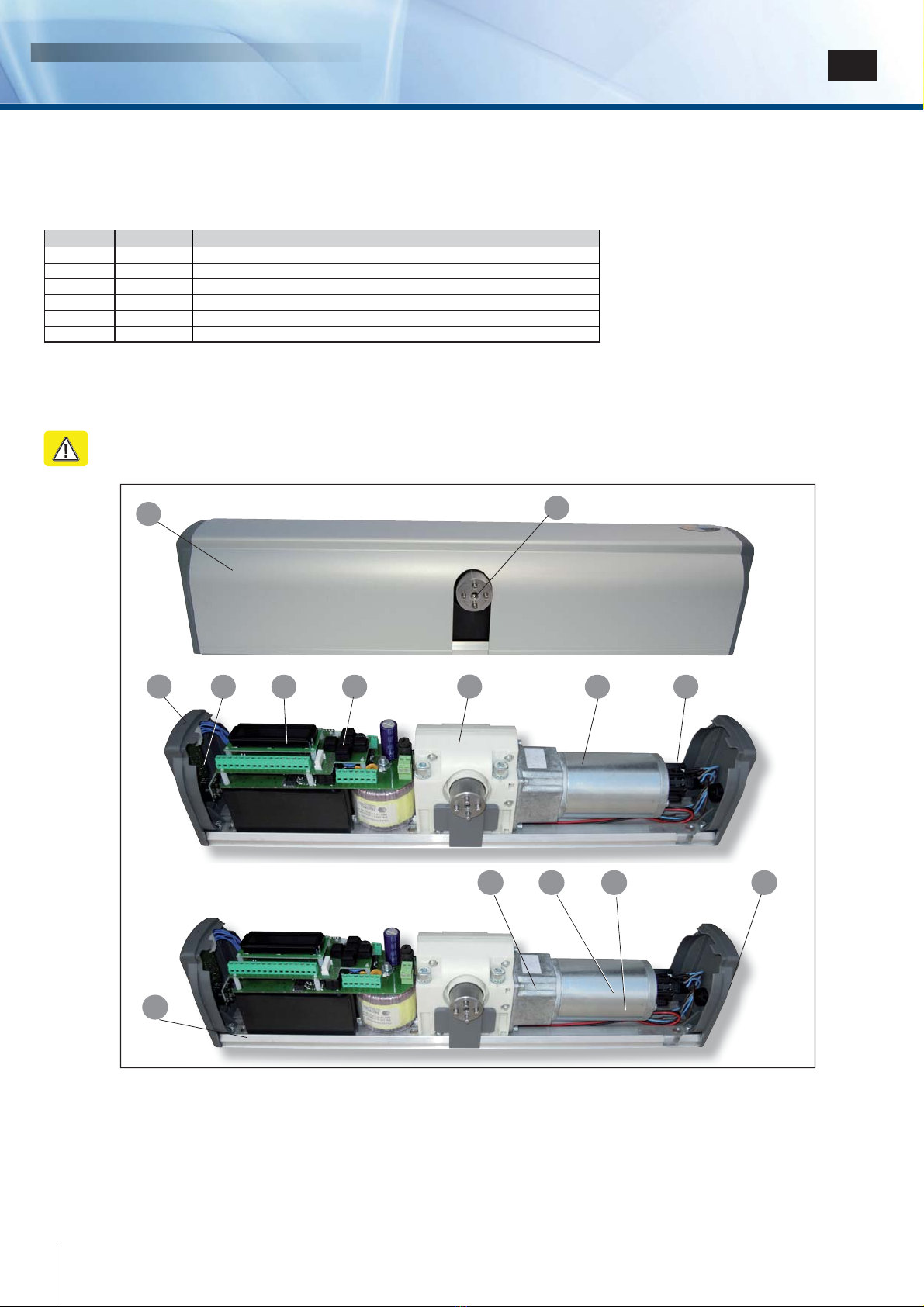
Identifying the product and its parts
Identifying the product and its parts
Digiway type DWPx102xx is a indoor operator for swing doors, with integrated electronic controller and radio receiver.
Digiway type DWPx102xx is a indoor operator for swing doors, with integrated electronic controller and radio receiver.
The opening and closing motion is electromechanical with backup battery which assures the operation in cases of power
The opening and closing motion is electromechanical with backup battery which assures the operation in cases of power
failure. The following versions are available:
failure. The following versions are available:
Legend
Legend
1 - Anodized aluminium cover
1 - Anodized aluminium cover
8 -
8 -
Motoriductor
Motoriductor
2 - Motor shaft
2 - Motor shaft
9 -
9 -
Encoder
Encoder
3 - Status led LP
3 - Status led LP
10 - Slot for coven opening
10 - Slot for coven opening
4 -
4 -
Receiver Card
Receiver Card
11 -
11 -
Toroidal transformer
Toroidal transformer
5 - Display LCD 12 -
5 - Display LCD 12 -
Backup battery
Backup battery
6 - 5-buttons keyboard
6 - 5-buttons keyboard
13 -
13 -
Battery cable with protection fuse
Battery cable with protection fuse
7 -
7 -
Gear box
Gear box
14 -
14 -
Operating mode selector
Operating mode selector
P/N Reference Description
F0543000054
F0543000054 DWPS102SCD
Single door operator for inswing doors with sliding arm
Single door operator for inswing doors with sliding arm
F0543000055
F0543000055 DWPS102ACD
Single door operator for outswing doors with articulated arm
Single door operator for outswing doors with articulated arm
F0543000056 DWPS102UCD
Single door operator for inswing or outswing doors with universal arm
Single door operator for inswing or outswing doors with universal arm
F0543000059
F0543000059 DWPS106SCD
16 Vac single door operator for inswing doors with sliding arm
16 Vac single door operator for inswing doors with sliding arm
F0543000058 DWPS106ACD
16 Vac single door operator for outswing doors with
16 Vac single door operator for outswing doors with
articulated arm
articulated arm
F0543000060
F0543000060 DWPS106UCD
16 Vac single door operator for inswing or outswing doors with universal arm
16 Vac single door operator for inswing or outswing doors with universal arm
11
78 95 6
3
10
12
12 13 14
4
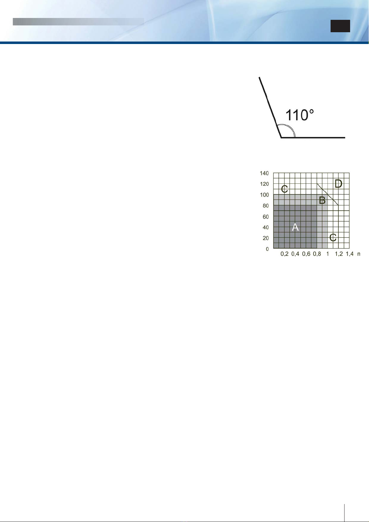
The operator is suitable for swing doors with max width of 1,2 m and max weight of 120 Kg ( Refer to diagram on page 7).
The operator is suitable for swing doors with max width of 1,2 m and max weight of 120 Kg ( Refer to diagram on page 7).
At the max speed the door can open and close within 3 sec. ( 90°), depending on door weight and dimensions .
At the max speed the door can open and close within 3 sec. ( 90°), depending on door weight and dimensions .
See the technical specifications in the following pages of this manual.
See the technical specifications in the following pages of this manual.
4cdvi.com
cdvigroup.com
Warning : the operator is suitable only for top-jamb fixing. Door leaf fixing is not allowed.
Warning : the operator is suitable only for top-jamb fixing. Door leaf fixing is not allowed.

INSTALLATION MANUAL
DIGIWAY PLUS
5
cdvi.com
cdvigroup.com
EN
Accessories
Accessories
Legend
Legend
Mounting kit
Mounting kit
1
5
Kit Articulated Arm
Kit Articulated Arm
Kit Sliding Arm
Kit Sliding Arm
1 - Articulated base arm 5 -
1 - Articulated base arm 5 -
Sliding base lever
Sliding base lever
2 - Arm 6 -
2 - Arm 6 -
Sliding block
Sliding block
3 -
3 -
Forearm
Forearm
7 -
7 -
Aluminium guide
Aluminium guide
4 - Door bracket 8 - Lateral plug
4 - Door bracket 8 - Lateral plug
9 - Junction for articulated base arm
9 - Junction for articulated base arm
3
4
2
6
7
8
Kit Universal
Kit Universal
9
Article
Article
Description Screw for
wallplugs
SX 8
Wallplugs
SX 8
Self
tapping
screws
Screw
M6x14 Mounting
plate Mounting
template
Q.ty
Q.ty
6
6
6
6
4
4
7
7
1
1
1
1

DIGIWAY PLUS
INSTALLATION MANUAL EN
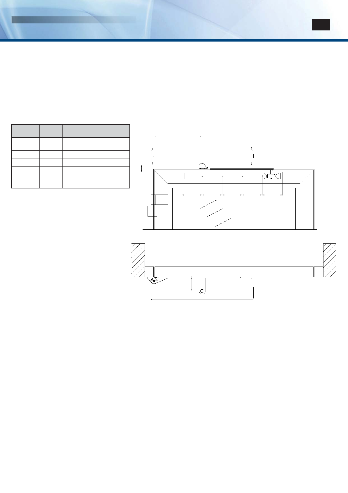
Overall dimensions and mounting quotes
Overall dimensions and mounting quotes
Mounting plate drilling quotes
Mounting plate drilling quotes
Accessories dimensions
Accessories dimensions
55 mm
55 mm
35 mm
35 mm
Optional extension
Optional extension
52
52
40
40
40
40
40
40
40
40
Cover lift point
Cover lift point
Cover lift point
Cover lift point
6cdvi.com
cdvigroup.com
INSTALLATION MANUAL
DIGIWAY PLUS
7
cdvi.com
cdvigroup.com
EN
Technical specifications
Technical specifications
•
•
General specifications
General specifications
Power supply:
Power supply:
.........................................................
.........................................................
230 Vac - 50 Hz
230 Vac - 50 Hz
Motor torque:
Motor torque:
...........................................................
...........................................................
15 Nm
15 Nm
Motor power:
Motor power:
............................................................
............................................................
33 W
33 W
Motor voltage:
Motor voltage:
..........................................................
..........................................................
24 Vdc
24 Vdc
Operating class:
Operating class:
.......................................................
.......................................................
5 ( heavy duty )
5 ( heavy duty )
Battery:
Battery:
....................................................................
....................................................................
12 Vdc 1,3 Ah
12 Vdc 1,3 Ah
Max motor consumption:
Max motor consumption:
........................................
........................................
6A @ 12V
6A @ 12V
Overall dimensions :
Overall dimensions :
................................................
................................................
511 x 90 x 110 mm
511 x 90 x 110 mm
Weight:
Weight:
....................................................................
....................................................................
5 Kg
5 Kg
Operating temperature:
Operating temperature:
...........................................
...........................................
-10
-10
÷
÷
+55°C
+55°C
IP Grade:
IP Grade:
.................................................................
.................................................................
IP22
IP22
Opening / closing time:
Opening / closing time:
............................................
............................................
3 ÷ 15 sec.
3 ÷ 15 sec.
Pause time:
Pause time:
..............................................................
..............................................................
3
3
÷
÷
90 sec.
90 sec.
Power for auxiliary devices:
Power for auxiliary devices:
.....................................
.....................................
13,5 Vdc / 500 mA [ max ]
13,5 Vdc / 500 mA [ max ]
Power for electrolock:
Power for electrolock:
.............................................
.............................................
12 Vdc / 1A
12 Vdc / 1A
[ max ]
[ max ]
Electrolock output relay:
Electrolock output relay:
..........................................
..........................................
( C-NO-NC) 10A / 12V
( C-NO-NC) 10A / 12V
Open door output relay
Open door output relay
............................................
............................................
( C-NO ) - 24 VA
( C-NO ) - 24 VA
Electrolock hold time:
Electrolock hold time:
..............................................
..............................................
Adjustable [ 0,1
Adjustable [ 0,1
÷ 40 Sec. ]
÷ 40 Sec. ]
Power failure autonomy:
Power failure autonomy:
..........................................
..........................................
270 cycles
270 cycles
Transmitters security protocol:
Transmitters security protocol:
................................
................................
Keeloq® Hopping Code
Keeloq® Hopping Code
TX memory:
TX memory:
.............................................................
.............................................................
50 transmitters
50 transmitters
Integrated receiver main specifications:
Integrated receiver main specifications:
..................
..................
433,92 MHz ASK /
433,92 MHz ASK /
-107 dBm
-107 dBm
Fire voltage input:
Fire voltage input:
....................................................
....................................................
12
12
÷ 48
÷ 48
Vac/dc
Vac/dc
•
•
Use conditions
Use conditions
•
•
Electronic card specifications
Electronic card specifications
•
•
Main features
Main features
Zone A
Zone A
: Very intense use : 600 cycles / day
: Very intense use : 600 cycles / day
Zone B
Zone B
:
:
Intense use
Intense use
: 200-300
: 200-300
cycles / day
cycles / day
Zone C
Zone C
: Use at reduced speed
: Use at reduced speed
Zone D : Not allowed
Zone D : Not allowed
Operating modes:
Operating modes:
Automatic ( I ) - Door free ( 0 ) - Door always open (II)
Automatic ( I ) - Door free ( 0 ) - Door always open (II)
Inputs: Re-open photocells ( NC)
Inputs: Re-open photocells ( NC)
Stop photocells ( NC )
Stop photocells ( NC )
Door Alway open
Door Alway open
( NO )
( NO )
Door free ( NO )
Door free ( NO )
External Radar ( NO )
External Radar ( NO )
Internal Radar ( NO )
Internal Radar ( NO )
Day / Night selection ( NO )
Day / Night selection ( NO )
Open / Close command ( NO )
Open / Close command ( NO )
Fire alarm voltage ( +V, -V) [optoisolated ]
Fire alarm voltage ( +V, -V) [optoisolated ]
Operating modes: Fully automatic, Always open, Door free;
Operating modes: Fully automatic, Always open, Door free;
Operating with single door, double door, with or without leaf overlapping;
Operating with single door, double door, with or without leaf overlapping;
Guided procedure for door travel limits characterization;
Guided procedure for door travel limits characterization;
Motor torque in opening and closing adjustable;
Motor torque in opening and closing adjustable;
Remote controls memorization and management;
Remote controls memorization and management;
Slow motion approaching the limits;
Slow motion approaching the limits;
Push & Go / Pull & Go function;
Push & Go / Pull & Go function;
Pause Time, Max Speed, Torque, Velocity adjustable;
Pause Time, Max Speed, Torque, Velocity adjustable;
Opening Jolt fully adjustable;
Opening Jolt fully adjustable;
Status bicolor LED;
Status bicolor LED;
Electrolock hold time and torque adjustable;
Electrolock hold time and torque adjustable;
Opening Jolt parameters adjustable;
Opening Jolt parameters adjustable;
Spring mode ( door always free, automatic closing );
Spring mode ( door always free, automatic closing );
Stop photocells range adjustable;
Stop photocells range adjustable;
“Fire mode”;
“Fire mode”;
Night / day mode;
Night / day mode;
Door open output relay.
Door open output relay.
Leaf width
Leaf width
Leaf weight
Leaf weight
Max Door opening angle
Max Door opening angle
Outputs:
Outputs:
Door open contact ( C-NO )
Door open contact ( C-NO )
External devices power 13,5 Vdc / 500 mA
External devices power 13,5 Vdc / 500 mA
Electrolock output contacts ( C-NO-NC )
Electrolock output contacts ( C-NO-NC )
Electrolock power 12 Vdc / 1A
Electrolock power 12 Vdc / 1 A
DIGIWAY PLUS
INSTALLATION MANUAL EN
Sliding arm version
Sliding arm version
First of all, check the stability of the door which has to be motorized, verifying that regularity of the motion in both
First of all, check the stability of the door which has to be motorized, verifying that regularity of the motion in both
directions ( open and close ) is without any friction from the complete close to the complete open status. If this is
directions ( open and close ) is without any friction from the complete close to the complete open status. If this is
not the case, make necessary improvements to the structure. Remove any manually operated lock (eg. requiring a
not the case, make necessary improvements to the structure. Remove any manually operated lock (eg. requiring a
physical lowering of the handle to open the door).
physical lowering of the handle to open the door).
Digiway plus
Digiway plus
does not need a door-stop fitted
does not need a door-stop fitted
to complete the open cycle.
to complete the open cycle.
This type of installation is addressed to inswing doors.
This type of installation is addressed to inswing doors.
1) Identify the dimensions of the motor, locate the fixing position, the holes for the cables and the 6 fixing holes making use
1) Identify the dimensions of the motor, locate the fixing position, the holes for the cables and the 6 fixing holes making use
of the mounting template provided;
of the mounting template provided;
2) Check the feasibility of the guide fixing, respecting the distance to the motor;
2) Check the feasibility of the guide fixing, respecting the distance to the motor;
3) Make 6 holes diameter Ø 8 mm and insert the 6 special plugs provided ;
3) Make 6 holes diameter Ø 8 mm and insert the 6 special plugs provided ;
4) Fix the plate to the wall using the special screws provided;
4) Fix the plate to the wall using the special screws provided;
5) Fix the motor to the mounting plate with the screws M6x14 provided;
5) Fix the motor to the mounting plate with the screws M6x14 provided;
6) Plug-in the sliding arm on the motor shaft and screw the fixing screw M6;
6) Plug-in the sliding arm on the motor shaft and screw the fixing screw M6;
7) Slide-in the sliding block into the guide;
7) Slide-in the sliding block into the guide;
8) Offer the guide to the door and mark the 4 fixing holes;
8) Offer the guide to the door and mark the 4 fixing holes;
9) Remove the sliding block and fix the guide to the door by using the 4 special screws provided;
9) Remove the sliding block and fix the guide to the door by using the 4 special screws provided;
10) Slide-in completely the white strip on the guide;
10) Slide-in completely the white strip on the guide;
11) Slide-in the sliding block into the guide and insert the two lateral plugs;
11) Slide-in the sliding block into the guide and insert the two lateral plugs;
12) Make all the electrical connections;
12) Make all the electrical connections;
13) Apply power;
13) Apply power;
14) Follow the procedure : «Getting started»;
14) Follow the procedure : «Getting started»;
15) Connect the Ground wire to the cover terminal and fix the cover.
15) Connect the Ground wire to the cover terminal and fix the cover.
E
A
B
C D D D C
Parameter Value
(mm) Description
A
A
240
240
(max)
(max)
Door hinge – motor axis
Door hinge – motor axis
distance
distance
B
B
35
35
Motor cover – guide distance
Motor cover – guide distance
C
C
102
102
Motor axis - guide edge
Motor axis - guide edge
D
D
100
100
Guide holes interaxis
Guide holes interaxis
E
E
70,5
70,5
Motor axis - vertical plane
Motor axis - vertical plane
distance
distance
8cdvi.com
cdvigroup.com

INSTALLATION MANUAL
DIGIWAY PLUS
9
cdvi.com
cdvigroup.com
EN
This part is addressed to outward door installations
This part is addressed to outward door installations
1) Identify the dimensions of the motor, locate the fixing position, the holes for the cables and the 6 fixing holes making
1) Identify the dimensions of the motor, locate the fixing position, the holes for the cables and the 6 fixing holes making
use of the mounting template provided;
use of the mounting template provided;
2) Make sure that the bracket of the articulated arm falls in the right position;
2) Make sure that the bracket of the articulated arm falls in the right position;
3) Make 6 holes diameter Ø 8 mm and insert the 6 special plugs provided ;
3) Make 6 holes diameter Ø 8 mm and insert the 6 special plugs provided ;
4) Fix the plate to the wall using the special screws provided;
4) Fix the plate to the wall using the special screws provided;
5) Fix the motor to the mounting plate with the screws M6x14 provided
5) Fix the motor to the mounting plate with the screws M6x14 provided
6) Fix the bracket to the door referring to the distance A of the table below;
6) Fix the bracket to the door referring to the distance A of the table below;
7) Plug in the articulated arm on the motor shaft and screw the fixing screw M6;
7) Plug in the articulated arm on the motor shaft and screw the fixing screw M6;
8) If the distance between the motor and the door is higher than that allowed, use the extension (
8) If the distance between the motor and the door is higher than that allowed, use the extension (
optional
optional
);
);
9) Fix the arm to the motor by using the screw M6x14 or M6x70 provided;
9) Fix the arm to the motor by using the screw M6x14 or M6x70 provided;
10) Make all the electrical connections;
10) Make all the electrical connections;
11) Apply power;
11) Apply power;
12)
12)
Follow the procedure : «Getting started»;
Follow the procedure : «Getting started»;
13) Connect the Ground wire to the cover terminal and fix the cover.
13) Connect the Ground wire to the cover terminal and fix the cover.
L1
L2
L3
A
B
Parameter Speed Power Description
(mm) (mm)
A
A
410
410
430
430
Door hinge – door bracket distance
Door hinge – door bracket distance
B
B
270
270
360
360
Door hinge – motor axis distance
Door hinge – motor axis distance
A - B
A - B
140
140
70
70
Motor axis – door bracket distance
Motor axis – door bracket distance
C
C
40
40
Bracket holes distance
Bracket holes distance
L1
L1
70,5
70,5
Motor axis – wall distance
Motor axis – wall distance
L2
L2
300
300
Base lever
Base lever
L3
L3
130 - 300
130 - 300
Arm extension
Arm extension

DIGIWAY PLUS
INSTALLATION MANUAL EN
Complete wiring diagram
Complete wiring diagram
Differential
Differential
magnetothermic
magnetothermic
circuit-braker
circuit-braker
3 pos. switch
3 pos. switch
autom / door free
autom / door free
/ always open
/ always open
NIght / Day
NIght / Day
Start/Stop
Start/Stop
Door open
Door open
relay
relay
Fire-alarm
Fire-alarm
voltage
voltage
Electrolock
Electrolock
FTC-S [ Stop ]
FTC-S [ Stop ]
FTC [ Re-open ]
FTC [ Re-open ]
Internal
Internal
Radar
Radar
External
External
Radar
Radar
Layout inswing door with sliding arm
Layout inswing door with sliding arm
Layout outswing door with articulated arm
Layout outswing door with articulated arm
Internal
Internal
Radar
Radar
External
External
Radar
Radar
FTC
FTC
FTC-S
FTC-S
Internal
Internal
Radar
Radar
External
External
Radar
Radar
FTC
FTC
FTC-S
FTC-S
Electronic card layout
Electronic card layout
Display LCD
Display LCD
Battery
Battery
connector
Fuse
Fuse
3,15A
3,15A
Programming
Programming
buttons
buttons
GND
GND
connection
connection
Monitor
Monitor
LED’s
LED’s
Terminal
Terminal
blocks A
blocks A
Terminal
Terminal
blocks
blocks
B
B
Serial
Serial
connection
connection
connector
connector
Fuse
Fuse
1A
1A
ESC : Return to upper level
Return to upper levelReturn to upper level
scroll UP / increase value
scroll UP / increase value
scroll DOWN / decrease value
scroll DOWN / decrease value
OK
OK
Not used
Not used
Programming buttons
Programming buttons
External switch
External switch
I 0 II
I 0 II
DOOR ALWAYS OPEN
DOOR ALWAYS OPEN
DOOR FREE
DOOR FREE
FULLY AUTOMATIC
FULLY AUTOMATIC
10 cdvi.com
cdvigroup.com

INSTALLATION MANUAL
DIGIWAY PLUS
11
cdvi.com
cdvigroup.com
EN
Connections detail
Connections detail
Electrical connections
Electrical connections
16-way terminal block
1Output C Open door relay
2Output NO Open door relay
3Input V- Fire alarm voltage
4Input V+ Fire alarm voltage
5Safety Input NC Stop Photocells [FTC-S]
6Safety Input C Photocells
7Safety Input NC Re-open Photocells [FTC]
8Input NO switch pos. I
9Input C switch pos. 0
10 Input NO switch pos. II
11 Input NA Radar external
12 Input C Radar
13 Input NO Radar internal
14 Input NO Day/Night switch
15 Input common
16 Input NO push-button open/close/stop
7-way terminal block
17 Output NO relay electrolock
18 Output C relay electrolock
19 Output NC relay electrolock
20 Output 0V external devices power
21 Output 13,5 Vdc external devices power
22 Output 0V electrolock power
23 Output 12 Vdc electrolock power
2-ways removable terminal block
24 Input Phase 230 Vac
25 Input Neutral 230 Vac
2-ways terminal block
26 Output 230 Vac for internal toroidal transformer
27 Output 230 Vac for internal toroidal transformer
2-ways terminal block
28 Input Motor BLACK cable
29 Input Motor RED cable
2-ways terminal block
30 Input from internal toroidal transformer
31 Input from internal toroidal transformer
Battery
Battery
+
+
-
-
FUSE 5A
FUSE 5A
to toroidal
to toroidal
transformer
transformer
to the motor
to the motor
OUT open
OUT open
door relay (*)
door relay (*)
FTC-S
FTC-S
FTC
FTC
Automatic
Automatic
Door free
Door free
Door open
Door open
RADAR Int.
RADAR Int.
RADAR Ext.
RADAR Ext.
Day/Night
Day/Night
Open/Close
Open/Close
Magnet
Magnet
External
External
magnet
magnet
supply
supply
Supply radars
Supply radars
& photocells
& photocells
Electrolock
Electrolock
Supply
Supply
Electrolock relay
Electrolock relay
from toroidal transformer
from toroidal transformer
or
or
Input 16 V~ [ Ref. DWPx106x ]
Input 16 V~ [ Ref. DWPx106x ]
(*) Open door relay
Door Status Closed Opening/Open/Closing
Relay OFF ON
DIGIWAY PLUS
INSTALLATION MANUAL EN
Meaning of LP LED messages
Meaning of LP LED messages
Function
Function LED GREEN LED ORANGE LED RED
ON
ON
blinking
blinking
ON
ON
blinking
blinking
ON
ON
blinking
blinking
fast blinking
fast blinking
Everything OK
Everything OK
O
O
Battery operated
Battery operated
O
O
Fire alarm
Fire alarm
O (fast)
O (fast)
Night Mode
Night Mode
O
O
Night Mode & battery
Night Mode & battery
operated
operated
O
O
Door free
Door free
-
-
-
-
-
-
-
-
-
-
-
-
-
-
Voltage calculation
Voltage calculation
in progress
in progress
O
O
Selflearning
Selflearning
red/green
red/green
Battery test
Battery test
O
O
Battery unleaded
Battery unleaded
O
O
GETTING STARTED
GETTING STARTED
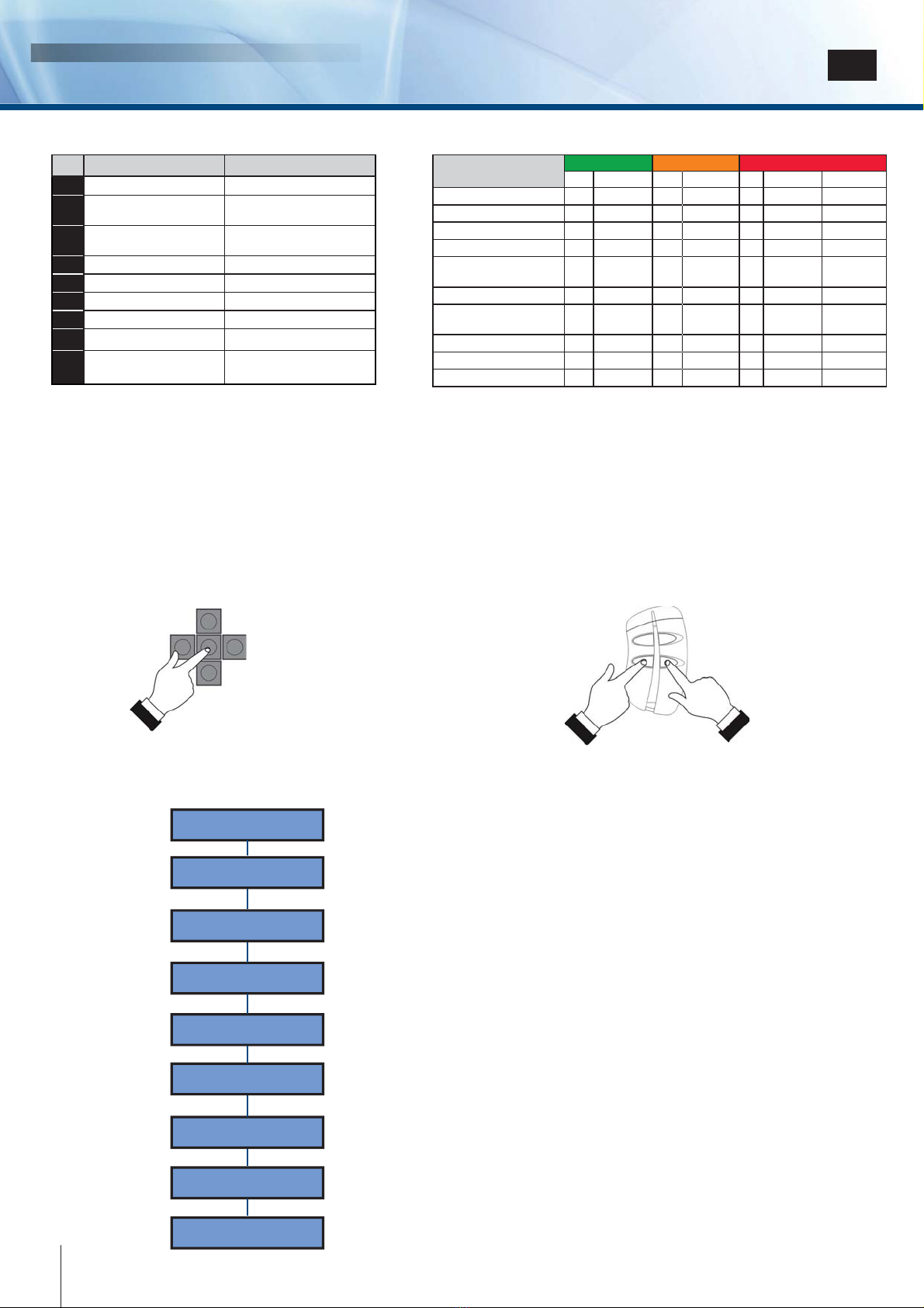
Digiway Plus is equipped with a 2x16 characters LCD Display and by a 5-keys keyboard. The operating configuration can be set navigating
Digiway Plus is equipped with a 2x16 characters LCD Display and by a 5-keys keyboard. The operating configuration can be set navigating
through several menus. The menu has a tree structure with a main menu and different sub-menus.
through several menus. The menu has a tree structure with a main menu and different sub-menus.
ACCESS to the MAIN MENU
ACCESS to the MAIN MENU
Push simultaneously the keys C + D of a radio
Push simultaneously the keys C + D of a radio
transmitter already memorized
transmitter already memorized
(within Digiway memory).
(within Digiway memory).
Hold the OK button down for
Hold the OK button down for
4 seconds.
4 seconds.
A
A
B
B
C
C
D
D
Main Menu structure
Main Menu structure
The main menu is composed by 9 submenus :
The main menu is composed by 9 submenus :
•
•
LANGUAGES :
LANGUAGES :
Selects the language of the display messages ;
Selects the language of the display messages ;
•
•
CONFIGURATION:
CONFIGURATION:
Operating mode settings (number of doors, electrolock, etc.) ;
Operating mode settings (number of doors, electrolock, etc.) ;
•
•
MAIN FUNCTIONS:
MAIN FUNCTIONS:
Adjustments (speed, force, etc);
Adjustments (speed, force, etc);
•
•
ADVANCED SETTING:
ADVANCED SETTING:
Special settings with more parameters
Special settings with more parameters
;
;
•
•
DOOR CALIBRATION:
DOOR CALIBRATION:
Selflearning of the door parameters;
Selflearning of the door parameters;
•
•
TX MANAGEMENT:
TX MANAGEMENT:
Management of the remote controls (add, remove, etc);
Management of the remote controls (add, remove, etc);
•
•
FACTORY DEFAULTS:
FACTORY DEFAULTS:
Restore to the factory settings;
Restore to the factory settings;
•
•
SYSTEM RESET:
SYSTEM RESET:
System restart;
System restart;
•
•
EXIT MENU:
EXIT MENU:
Exit.
Exit.
Electronic card LED’s
Electronic card LED’s
LED ON LED OFF
L1 Fire voltage OK Fire voltageABSENT
L2 NC contact stop photocells
closed NC contact stop photocells
open
L3 NC contact re-open photo-
cells closed NC contact re-open photo-
cells open
L4 Automatic mode -
L5 Door always open -
L6 External radar active -
L7 Internal radar active -
L8 Night mode Day mode
L9 Open/close command
active -
Main Menu
Configuration
Main Menu
Advanced setting
Main Menu
Door calibration
Main Menu
TX Management
Main Menu
System Reset
Main Menu
Languages
Main Menu
Factory defaults
Main Menu
Main functions
Main Menu
Exit Menu
OR
OR
12 cdvi.com
cdvigroup.com

INSTALLATION MANUAL
DIGIWAY PLUS
13
cdvi.com
cdvigroup.com
EN
Guided configuration
Guided configuration
The operator is supplied with a 4-button transmitter included. On completion of the mechanical fixing and the electric connections, proceed
The operator is supplied with a 4-button transmitter included. On completion of the mechanical fixing and the electric connections, proceed
with the memorization of the transmitter into the internal memory inside Digiway. This transmitter can then set-up of all parameters, without
with the memorization of the transmitter into the internal memory inside Digiway. This transmitter can then set-up of all parameters, without
accessing the 5 buttons
accessing the 5 buttons
onboard
onboard
.
.
The transmitter keys corresponds to the onboard push-button according to the next diagram:
The transmitter keys corresponds to the onboard push-button according to the next diagram:
The set-up of the operator can be divided into 5 steps:
The set-up of the operator can be divided into 5 steps:
•
•
STEP I : INITIAL SETUP
STEP I : INITIAL SETUP
( preliminary actions )
( preliminary actions )
•
•
STEP II : CONFIGURATION
STEP II : CONFIGURATION
( set-up of the basic operating mode )
( set-up of the basic operating mode )
•
•
STEP
STEP
III : DOOR CALIBRATION
III : DOOR CALIBRATION
( automatic detection of the door characteristics )
( automatic detection of the door characteristics )
•
•
STEP
STEP
IV : ADJUSTMENTS
IV : ADJUSTMENTS
( further adjustments and personalization )
( further adjustments and personalization )
•
•
STEP
STEP
V : SPECIAL PARAMETERS
V : SPECIAL PARAMETERS
(
(
set-up of the
set-up of the
advanced parameters )
advanced parameters )
Press the OK button of the keyboard
Press the OK button of the keyboard
for
for
4 sec
4 sec
until the display enters the main menu ;
until the display enters the main menu ;
Select the language by scolling the possibile choices with the UP and DOWN buttons
Select the language by scolling the possibile choices with the UP and DOWN buttons
Press OK to confirm: the display shows the message OK and then displays all messages in the new language;
Press OK to confirm: the display shows the message OK and then displays all messages in the new language;
Exit from the menu with the button ESC.
Exit from the menu with the button ESC.
Scroll through the main menu, select
Scroll through the main menu, select
TX MANAGEMENT
TX MANAGEMENT
submenu and press OK
submenu and press OK
Select the option
Select the option
ADD TX
ADD TX
and press
and press
OK
OK
Press the transmitter key A (top-left button): the display will show the S/N, confirming the memorization
Press the transmitter key A (top-left button): the display will show the S/N, confirming the memorization
Exit from the menu by pressing the ESC button.
Exit from the menu by pressing the ESC button.
Exit from the main menu selecting EXIT MENU.
Exit from the main menu selecting EXIT MENU.
From this time on the remote control is enabled to access the main menu. Enter simply by pressing simultaneously keys
From this time on the remote control is enabled to access the main menu. Enter simply by pressing simultaneously keys
C + D
C + D
.
.
NOTE : ONLY THE FIRST TRANSMITTER MEMORIZED CAN ACCESS THE MAIN MENU! All the next added transmitters can only
NOTE : ONLY THE FIRST TRANSMITTER MEMORIZED CAN ACCESS THE MAIN MENU! All the next added transmitters can only
open the door!
open the door!
The key OK of the transmitter can do multiple functions: OK if you are in the menu, START / STOP in normal operating.
The key OK of the transmitter can do multiple functions: OK if you are in the menu, START / STOP in normal operating.
ESC
ESC
DOWN
DOWN
UP
UP
UP
UP
DOWN
DOWN
ESC
ESC
STEP I: INITIAL SETUP
2
1
3
4
5
6
7
8
9

DIGIWAY PLUS
INSTALLATION MANUAL EN
Parameter Description Option Default
Num. Doors Sets the number of Doors ONE DOOR / TWO DOORS ONE DOOR
Electrolock Enables electrolock NO LOCK / ENABLE NO LOCK
Opening Jolt Enables the opening Jolt : short pulse of closing before
opening. Usefull to unlock the electrolock in windy
situations ENABLE / DISABLE DISABLE
Push & Open Opens automatically the door with a short push. ENABLE / DISABLE ENABLE
Push & Close Closes the door with a short push even in pause status. ENABLE / DISABLE ENABLE
Wind Stop Keeps the door closed in presence of wind which
pushes the door. See Advanced Sets how to set the
level of the closing force used. ENABLE / DISABLE DISABLE
Autoreclosing Enables the automatic reclosing of the door ENABLE / DISABLE ENABLE
Radar ‘I’ Mode Disables the INTERNAL radar input while the door is
closing. NEVER / CLOSING / ALWAYS NEVER
Radar ‘E’ Mode Disables the EXTERNAL radar input while the door is
closing. NEVER / CLOSING / ALWAYS NEVER
Day / Night Set the Night / Day mode. In Night mode the External
radar is disabled. DAY & NIGHT / NIGHT NIGHT
Disabled Mode Disabled access mode ( See paragraph Disabled
access settings) ENABLE / DISABLE DISABLE
Open Command Functions of the main command which can open, close
and stop ( this will be the function assigned to the open
button ( terminals 15-16 ) and to the radio transmitter
OPEN - OPEN/CLOSE -
OPEN-CLOSE/STOP OPEN/CLOSE
Mode Spring Spring function: if the door is closed, it remains free
and can be pushed manually; once open the door will
reclose after the pause time set. ENABLE / DISABLE DISABLE
2 Doors Overlap Overlap of the leaves ( in case of double doors ) ENABLE / DISABLE DISABLE
Door Type Leaf MASTER or leaf SLAVE ( in case of double doors ) MASTER / SLAVE MASTER
Arm Type Articulated or sliding arm. The controller sets automati-
cally the best value of the internal parameters according
to the arm type selected SLIDING / ARTICULATED SLIDING
Fire Signal
Fire signal management. When this option is enabled
the door operates regularly only if the fire power V-/V+
is present. If the fire power falls down ( for a fire alarm in
progress) the door reacts according to the choice set in
the advanced sets options )
ENABLE / DISABLE DISABLE
Step II allows you to set all the basic parameters of the operator, according to the type of door to automate
Step II allows you to set all the basic parameters of the operator, according to the type of door to automate
The submenu CONFIGURATION consists of 18 parameters.
The submenu CONFIGURATION consists of 18 parameters.
Each parameter can have 2 or more values.
Each parameter can have 2 or more values.
For each parameter there is a preset factory value. If the function FACTORY DEFAULT of the main menu is used, all the parameters are
For each parameter there is a preset factory value. If the function FACTORY DEFAULT of the main menu is used, all the parameters are
reset to those values.
reset to those values.
See the description of each parameter in the following table:
See the description of each parameter in the following table:
STEP II: CONFIGURATION
ATTENTION
ATTENTION
: Any change carried out needs a complete cycle ( open, pause, close ) or a system reset
: Any change carried out needs a complete cycle ( open, pause, close ) or a system reset
to be
to be
implemented
implemented
.
.
14 cdvi.com
cdvigroup.com

INSTALLATION MANUAL
DIGIWAY PLUS
15
cdvi.com
cdvigroup.com
EN
DIGIWAY PLUS is equipped with an innovative software which fits the internal parameters to the door characteristics. The calibration sets
DIGIWAY PLUS is equipped with an innovative software which fits the internal parameters to the door characteristics. The calibration sets
the door travel limits and launches a special 5 cycles routine for the automatic detection of the door characteristics.
the door travel limits and launches a special 5 cycles routine for the automatic detection of the door characteristics.
For the calibration follow the next steps:
For the calibration follow the next steps:
Set the EXTERNAL SWITCH in position ‘0’
‘0’ = DOOR FREE (*)
1
1
Action
Action
Display
Display
Select Door Calibration from the Main
Manu and press OK
2
2
CLOSE THE DOOR COMPLETELY and
press OK
OPEN THE DOOR COMPLETELY and
press OK (*)
4
4
Select Autocalibration from the Door Cali-
bration Menu and press OK
5
5
6
6
Press OK: the door begins 5 cycles of
opening and closing until asking for
SAVE
7
7
Press OK. The calibration cycle is over.
The door remains open
Set the EXTERNAL SWITCH in position ‘I’
= AUTOMATIC. The door closes and the
calibration is completed.
8
8
Door Calibration
Door Limits
Close Door
Then Press OK
Open Door
Then Press OK
Thank You
Door Calibration
Autocalibration
Autocalibration
Wizard
Proceed with
Autocalibration?
Closing ...
Measure 1/5...
Tm= XX,X V= XX
Save ?
....C...........................
P=000,0 V=00,0
Door Calibration
Select Door Limits from the submenu of
Door Calibration and press OK
3
3
9
9
Door Calibration
Door Limits
Set Door Limits
Wizard
STEP III: DOOR CALIBRATION [ SINGLE LEAF ]
(*) : It is advisable to open the door 10 cm more of the final position desired
(*) If this set is not followed, the software will give a warning.
NOTE : Before proceeding with the calibration check the connection of the battery red/black cable to the main board and disconnect tem-
porarily the magnetic lock ( when used ).
Warning : whilst the Digiway is
going trough its 5 learning cycles,
as it opens very quickly, it is
dangerous the passage across the
door.

DIGIWAY PLUS
INSTALLATION MANUAL EN
ADJUSTMENTS
ADJUSTMENTS
The maximum speed, the torque and the pause time are automatically calculated by the system during the door calibration.
The maximum speed, the torque and the pause time are automatically calculated by the system during the door calibration.
If you prefer to adjust the parameters manually to tailor the door travel, then it is necessary to access the submenu MAIN FUNCTIONS
If you prefer to adjust the parameters manually to tailor the door travel, then it is necessary to access the submenu MAIN FUNCTIONS
from the main menu. See following table for the explanation of the parameters.
from the main menu. See following table for the explanation of the parameters.
Each parameter can be adjusted using the keyboard buttons or
Each parameter can be adjusted using the keyboard buttons or
transmitter keys.
transmitter keys.
Main Functions Description Values NOTES
Open Speed Sets the maximum speed reached by the
door during opening. 0 - 100%
At the end of the door calibration the systems sets automatically the
max open speed at a special value. By increasing this value, the total
open time can reduce - be aware that in order to respect the end
opening point, the door may slow down before reaching the max speed.
Close Speed Sets the maximum speed reached by the
door during closing. 0 - 100%
At the end of the door calibration the systems sets automatically the
max close speed at a special value. By increasing this value, the total
close time can reduce - be aware that in order to respect the end closing
point, the door may slow down before reaching the max speed.
Pause Time Pause time - this is the time remains
open before automatically closing again 1 - 99 SEC. The preset factory value is 10 sec.
Open Torque Max torque of the door during opening. 0 - 100% The max opening torque is set automatically by the system at the end of
the door calibration to the max value (100 %). In the case of very light or
sensitive doors, it may be necessary to decrease this value.
Close Torque Max torque of the door during closing 0 - 100%
The max closing torque is set automatically by the system, at the end
of the door calibration, to the max value ( 100 %). Decrease this value
in case of very light or sensitive doors, or to respect the regulations for
disabled access.
Velocity Velocity of the door: rapidity of the door
to reach the max speed set, and to
mantain this value along all its travel. 0 - 100%
The default value for this parameter is 70%. The more this value, the
less is the total travel time, because the door maintains a high value of
speed for a longer time. Values too high for this parameter can cause
“door bounce”, especially for heavy doors (see motion diagram).
Open Speed
|||||||||||||||||........................... 45%
To increase the value press the key UP
To increase the value press the key UP
To decrease the value press the key DOWN
To decrease the value press the key DOWN
Press OK to confirm.
Press OK to confirm.
Press ESC to exit without saving.
Press ESC to exit without saving.
A bar will appear on the display, proportional to the value and the numeric value of the parameter .
A bar will appear on the display, proportional to the value and the numeric value of the parameter .
ESC
ESC
DOWN
DOWN
UP
UP
UP
UP
DOWN
DOWN
ESC
ESC
CURRENT CALCULATION CYCLES
CURRENT CALCULATION CYCLES
At the end of the door calibration, the door will operate normally.
At the end of the door calibration, the door will operate normally.
However, to complete the calibration the system needs 2 more complete cycles to calculate the 2 currents ( called “i” and “I”) necessary for
However, to complete the calibration the system needs 2 more complete cycles to calculate the 2 currents ( called “i” and “I”) necessary for
obstacle management.
obstacle management.
Until the 2 cycles are completed, the external LED LP will blink RED.
Until the 2 cycles are completed, the external LED LP will blink RED.
During the 2 cycles, before the completion of
During the 2 cycles, before the completion of
this calculation, if the door knocks meets an obstacle, the obstacle sensitivity used will be the factory value, which may not fit perfectly with
this calculation, if the door knocks meets an obstacle, the obstacle sensitivity used will be the factory value, which may not fit perfectly with
the door characteristics, therefore:
the door characteristics, therefore:
“It is highly recommended to ensure the door completes these 2 cycles without any interruption. When completed,
“It is highly recommended to ensure the door completes these 2 cycles without any interruption. When completed,
the external LED will illuminate Green, and the door calibration is completed.”
the external LED will illuminate Green, and the door calibration is completed.”
Motion
Motion
diagram
diagram
STEPIV : ADJUSTMENTS
Velocity = 0%
Velocity = 0%
Velocity = 100%
Velocity = 100%
t
t
1
1
v
v
t
t
Vmax
Vmax
t
t
2
2
t
t
3
3
16 cdvi.com
cdvigroup.com

INSTALLATION MANUAL
DIGIWAY PLUS
17
cdvi.com
cdvigroup.com
EN
DIGIWAY PLUS is equipped with many further parameters (all adjustable) to fit better to any type of installation. From the main menu select
DIGIWAY PLUS is equipped with many further parameters (all adjustable) to fit better to any type of installation. From the main menu select
ADVANCED SET to enter this submenu, which allows more adjustments.
ADVANCED SET to enter this submenu, which allows more adjustments.
Advanced Setting
Electrolock Time Electrolock Time
|||||||||||||||||...................0,5 SEC.
It is possible to pause the electrolock release time from 0,1 to 40 sec. depending on the
It is possible to pause the electrolock release time from 0,1 to 40 sec. depending on the
lock/door type . Press the UP or DOWN buttons to increase or decrease the pause time
lock/door type . Press the UP or DOWN buttons to increase or decrease the pause time
and confirm with OK.
and confirm with OK.
Default value = 0,5 Sec
Default value = 0,5 Sec
Advanced Setting
Opening Jolt Time Opening Jolt Time
|||||||||||||||||...................0,5 SEC.
The opening jolt, when enabled, is a short closing motion before the operator begins
The opening jolt, when enabled, is a short closing motion before the operator begins
opening - this relieves pressure of “side-load” for some locking devices. It’s possible to
opening - this relieves pressure of “side-load” for some locking devices. It’s possible to
adjust this time from
adjust this time from
0,1 to 40 sec. depending on the type of electrolock and door.
0,1 to 40 sec. depending on the type of electrolock and door.
Press
Press
the UP or DOWN buttons to increase or decrease the time and confirm with OK.
the UP or DOWN buttons to increase or decrease the time and confirm with OK.
Default value = 0,5 Sec
Default value = 0,5 Sec
1)
1)
2)
2)
Advanced Setting
Open Delay Open Delay Time
|||||||||||||||||...................0,5 SEC.
It is possible to add a short delay to the door motion to allow the electrolock bolt to
It is possible to add a short delay to the door motion to allow the electrolock bolt to
exit completely from its keeper, ensuring the door is fully unlocked. This can be useful
exit completely from its keeper, ensuring the door is fully unlocked. This can be useful
when using motorised locks. The open delay is set by pressing
when using motorised locks. The open delay is set by pressing
UP or DOWN buttons to
UP or DOWN buttons to
increase or decrease
increase or decrease
from
from
0,1 to 40 sec
0,1 to 40 sec
and confirm with OK
and confirm with OK
.
.
Default value = 0,5 Sec
Default value = 0,5 Sec
4)
4)
LOCK
LOCK
MOTOR
MOTOR
START
START
Delay
Delay
Advanced Setting
Open Jolt Torque Open Jolt Torque
|||||||||||||||||.....................20%
It is possible to adjust the torque of the motor during the opening jolt pulse.
It is possible to adjust the torque of the motor during the opening jolt pulse.
This is adjusted depending on the mechanical resistance of the door. Press the
This is adjusted depending on the mechanical resistance of the door. Press the
UP or
UP or
DOWN buttons to increase or decrease the value and confirm with OK.
DOWN buttons to increase or decrease the value and confirm with OK.
Default value =
Default value =
20%.
20%.
3)
3)
Advanced Setting
Wind Stop Torque Wind Stop Torque
|||||||||||||||||......................10%
It is possible to adjust the torque of the motor when the wind stop utility is enabled. This
It is possible to adjust the torque of the motor when the wind stop utility is enabled. This
allows changing the value of the force applied by the door related to the wind pressure.
allows changing the value of the force applied by the door related to the wind pressure.
Press the UP or DOWN buttons to increase or decrease the torque and confirm with
Press the UP or DOWN buttons to increase or decrease the torque and confirm with
OK.
OK.
Default value =
Default value =
50%.
50%.
5)
5)
Main Functions Description Value NOTES
O.D. Type Sets the obstacles detection criteria
C1+C2
C1+C2+C3
C1+C2+C4
C1+C2+C3+C4
By default the motor detects an obstacle when the speed becomes
almost zero (C1) and the current increases over a preset threshold (C2).
The criteria C3 intervenes after the speed decreases under 2/3 of the
max speed, and causes the door to stop.
C3 is not active during the current calculus cycles.
The criteria C4 intervenes if the current consumed exceeds 175% of the
current consumed during the preset.
According to the type of door (resistance, balance, weight, width etc) it is
possible to adjust the reaction of the door against an obstacle.
The first 2 criteria are always present. It is possible to add the criteria C3
or C4 or both.
Default value = C1+C2.
O.D. Reactivity Sets the reaction time against an
obstacle 0,1 - 5 sec.
Use the UP or DOWN keys to adjust this time : the higher the value,
the longer will be the contact of the door against the obstacle (less
sensitive).
Default value = 0,1 Sec.
STEP IV: ADJUSTMENTS (continued...)
STEP IV: ADJUSTMENTS (continued...)
STEP V: ADVANCED SETTINGS
Please contact your local office for further infomation regarding Obstacle Detection (O.D.)

DIGIWAY PLUS
INSTALLATION MANUAL EN
STEP V: ADVANCED SETTINGS (Continued...)
STEP V: ADVANCED SETTINGS (Continued...)
Advanced Setting
Ex Power Open Enable / Disable
When enabled, adds one more
When enabled, adds one more
OPENING
OPENING
pulse after the regular
pulse after the regular
OPENING
OPENING
cycle to
cycle to
compensate possible friction or door unbalance.
compensate possible friction or door unbalance.
Enable or disable this function with the UP or DOWN buttons and confirm with OK
Enable or disable this function with the UP or DOWN buttons and confirm with OK
Default value = DISABLE
Default value = DISABLE
8)
8)
Advanced Setting
Ex Power Close Enable / Disable
When enabled, adds one more
When enabled, adds one more
CLOSING
CLOSING
pulse after the regular
pulse after the regular
CLOSING
CLOSING
cycle to
cycle to
compensate possible friction or door unbalance.
compensate possible friction or door unbalance.
Enable or disable this function with the UP or DOWN buttons and confirm with OK
Enable or disable this function with the UP or DOWN buttons and confirm with OK
Default value = DISABLE
Default value = DISABLE
11)
11)
Advanced Setting
Extra Close Time Extra Close Time
|||||||||||||||||......................0 SEC.
This function allows to set the duration
This function allows to set the duration
TIME
TIME
of the
of the
CLOSING
CLOSING
extra pulse
extra pulse
Change the value by pressing the UP or DOWN buttons and confirm with OK.
Change the value by pressing the UP or DOWN buttons and confirm with OK.
Default value = 0 SEC.
Default value = 0 SEC.
13)
13)
Advanced Setting
Fire Release Fire Release
Open/Free/Closed
When the Fire Release function is enabled, it’s possible to set the reaction of the door
When the Fire Release function is enabled, it’s possible to set the reaction of the door
depending on the failure of the Fire power ( V+, V-) :
depending on the failure of the Fire power ( V+, V-) :
•
•
DOOR FREE
DOOR FREE
= In case of
= In case of
Fire Power
Fire Power
failure the door becomes FREE
failure the door becomes FREE
•
•
DOOR OPEN
DOOR OPEN
= In case of
= In case of
Fire Power
Fire Power
failure the door opens and stays OPEN until
failure the door opens and stays OPEN until
the fire power is reset or the function of the
the fire power is reset or the function of the
Menu Configuration
Menu Configuration
is disabled.
is disabled.
•
•
DOOR CLOSED LOCKED
DOOR CLOSED LOCKED
= Door CLOSED and lock active
= Door CLOSED and lock active
•
•
DOOR CLOSED UNLOCKED
DOOR CLOSED UNLOCKED
=
=
Door CLOSED and lock disactive
Door CLOSED and lock disactive
14)
14)
Advanced Setting
Max Obst Cycles Max Obst Cycles
|||||||||||||||||......................000
When the door meets an obstacle during closing, it re-opens immediately. At the end of
When the door meets an obstacle during closing, it re-opens immediately. At the end of
the pause time, it re-closes slowly. If the obstacle is still present the cycle restarts.
the pause time, it re-closes slowly. If the obstacle is still present the cycle restarts.
It is possible to set the max number of re-closing attempts by the door before stopping to
It is possible to set the max number of re-closing attempts by the door before stopping to
await a definitive command. Change this parameter (from
await a definitive command. Change this parameter (from
1
1
to
to
256)
256)
by pressing the
by pressing the
UP
UP
or DOWN
or DOWN
buttons and confirm with OK.
buttons and confirm with OK.
Default value = 4 attempts.
Default value = 4 attempts.
15)
15)
Advanced Setting
Dynamic Pause Enable / Disable
The dynamic pause is a function which automatically adjusts the pause time
The dynamic pause is a function which automatically adjusts the pause time
programmed, avoiding too many closing attempts of the door in high traffic situations.
programmed, avoiding too many closing attempts of the door in high traffic situations.
When enabled, this function increases by 1 sec. the pause time programmed each time
When enabled, this function increases by 1 sec. the pause time programmed each time
it detects
it detects
a passage through the door during the closing phase, and restarts the time
a passage through the door during the closing phase, and restarts the time
when the passage is detected against when the door is open.
when the passage is detected against when the door is open.
Once the door completes its cycle up to the closed status, the pause time is reset to the
Once the door completes its cycle up to the closed status, the pause time is reset to the
programmed value.
programmed value.
Press UP or DOWN buttons to enable or disable the function and confirm with OK
Press UP or DOWN buttons to enable or disable the function and confirm with OK
Default value = DISABLE.
Default value = DISABLE.
6)
6)
Advanced Setting
FTC-S Exclusion FTC-S Exclusion
|||||||||||||||||......................000
If the door is next to a wall and is using a curtain protection device, it may be necessary
If the door is next to a wall and is using a curtain protection device, it may be necessary
to prevent the device being activated by the wall to allow a complete opening of the leaf.
to prevent the device being activated by the wall to allow a complete opening of the leaf.
Set the zone width as percentage of the full door motion using the UP or DOWN buttons
Set the zone width as percentage of the full door motion using the UP or DOWN buttons
to increase or decrease the value.
to increase or decrease the value.
000 = Door OPEN
000 = Door OPEN
100 = Door CLOSED
100 = Door CLOSED
Example
Example
: if you want to disable the curtain device when the leaf is open at the 80% of
: if you want to disable the curtain device when the leaf is open at the 80% of
the complete travel, set the value to 20.
the complete travel, set the value to 20.
WARNING: the excluded zone may become a health & safety hazard
WARNING: the excluded zone may become a health & safety hazard
because it not protected!
because it not protected!
7)
7)
door
door
FTC-S active zone
FTC-S active zone
excluded zone
excluded zone
wall
wall
18 cdvi.com
cdvigroup.com
Advanced Setting
Ex Open Torque Ex Open Torque
|||||||||||||||||......................50 %
This function allows to set the
This function allows to set the
TORQUE
TORQUE
of the
of the
OPENING
OPENING
extra pulse
extra pulse
Change the value by pressing the UP or DOWN buttons and confirm with OK.
Change the value by pressing the UP or DOWN buttons and confirm with OK.
Default value = 50%
Default value = 50%
9)
9)
Advanced Setting
Extra Open Time Extra Open Time
|||||||||||||||||......................0 SEC.
This function allows to set the duration
This function allows to set the duration
TIME
TIME
of the
of the
OPENING
OPENING
extra pulse
extra pulse
Change the value by pressing the UP or DOWN buttons and confirm with OK.
Change the value by pressing the UP or DOWN buttons and confirm with OK.
Default value = 0 SEC.
Default value = 0 SEC.
10)
10)
Advanced Setting
Ex Close Torque Ex Close Torque
|||||||||||||||||......................50 %
This function allows to set the
This function allows to set the
TORQUE
TORQUE
of the
of the
CLOSING
CLOSING
extra pulse
extra pulse
Change the value by pressing the UP or DOWN buttons and confirm with OK.
Change the value by pressing the UP or DOWN buttons and confirm with OK.
Default value = 50%
Default value = 50%
12)
12)

INSTALLATION MANUAL
DIGIWAY PLUS
19
cdvi.com
cdvigroup.com
EN
Advanced Setting
Display Display Mode is
Expert / Normal
It’s possible to change the information displayed on the LCD setting to NORMAL or
It’s possible to change the information displayed on the LCD setting to NORMAL or
EXPERT mode.
EXPERT mode.
In EXPERT Mode all the main parameters of the motion will be displayed according to
In EXPERT Mode all the main parameters of the motion will be displayed according to
the following diagram:
the following diagram:
MoOcCBXbsMiIUJ
P=-000.0 V=-00.0
16)
16)
LEGEND
LEGEND
DISPLAY EXPERT MODE
DISPLAY EXPERT MODE
M / S
M / S
o
o
O
O
c
c
C
C
B
B
1,2,3,4, f
1,2,3,4, f
b
b
s
s
M
M
i
i
I
I
U
U
J/E
J/E
Master /
Master /
Slave
Slave
Opening
Opening
Open
Open
Closing
Closing
Closed
Closed
Obstacle
Obstacle
Obstacle
Obstacle
type
type
restart for
restart for
obstacle
obstacle
Stop
Stop
Motor
Motor
Opening
Opening
current
current
Closing
Closing
current
current
Elec-
Elec-
trolock
trolock
Opening
Opening
Jolt
Jolt
Position (+/-)
Position (+/-)
Speed: rpm/10
Speed: rpm/10
P
P
V
V
Disabled access settings
Disabled access settings
Door lenght
Door lenght
Door weight
Door weight
50 Kg
50 Kg
60 Kg
60 Kg
70 Kg
70 Kg
80 Kg
80 Kg
90 Kg
90 Kg
750 mm
750 mm
3,0 s
3,0 s
3,1 s
3,1 s
3,2 s
3,2 s
3,3 s
3,3 s
3,5 s
3,5 s
850 mm
850 mm
3,1 s
3,1 s
3,1 s
3,1 s
3,2 s
3,2 s
3,4 s
3,4 s
3,6 s
3,6 s
1000 mm
1000 mm
3,2 s
3,2 s
3,4 s
3,4 s
3,7 s
3,7 s
4,0 s
4,0 s
4,2 s
4,2 s
1200 mm
1200 mm
3,8 s
3,8 s
4,2 s
4,2 s
4,5 s
4,5 s
4,8 s
4,8 s
5,1 s
5,1 s
According to the Regulation, with the option DISABLE MODE [see. Menu Configuration] set on ENABLE, the minimum Pause time is
According to the Regulation, with the option DISABLE MODE [see. Menu Configuration] set on ENABLE, the minimum Pause time is
stated at 5 Sec. Adjust the motor torque using the features of the Main Functions menu to get the value of 67 N, measured at 25 mm from
stated at 5 Sec. Adjust the motor torque using the features of the Main Functions menu to get the value of 67 N, measured at 25 mm from
the main edge of the leaf. Check the min slowing down time during the closing ( last 10°) which must be 1,5 sec. If the value found is
the main edge of the leaf. Check the min slowing down time during the closing ( last 10°) which must be 1,5 sec. If the value found is
different, act on the Closing Speed parameter.
different, act on the Closing Speed parameter.
Warning : Disabled access doors must be identified with proper indications.
Warning : Disabled access doors must be identified with proper indications.
Advanced Setting
Approach speed Approach speed
|||||||||||||||||......................2
It’s possible to change the approach speed during the final closing.
It’s possible to change the approach speed during the final closing.
This can be usefull if the door finds some friction in the last approaching motion where is
This can be usefull if the door finds some friction in the last approaching motion where is
searching for the close position.
searching for the close position.
Default value = 3.
Default value = 3.
17)
17)
Advanced Setting
Obst. detection % Obst. detection %
|||||||||||||||||......................2
It’s possible to change the percentage of the complete
It’s possible to change the percentage of the complete
door
door
trip after which the door
trip after which the door
doesn’t detects an obstacle but assign the stop to the close position.
doesn’t detects an obstacle but assign the stop to the close position.
Default value = 2%
Default value = 2%
18)
18)
Advanced Setting
Closing delay Closing delay
|||||||||||||||||......................0 SEC
If the operator is used for disabled access [ in compliance with the Regulations EN12650-1, EN 12650-2 ] , adjust the opening and
If the operator is used for disabled access [ in compliance with the Regulations EN12650-1, EN 12650-2 ] , adjust the opening and
closing speed of the door to obtain the following travel times
closing speed of the door to obtain the following travel times
19)
19)
EX POWER
EX POWER
CLOSE
CLOSE
OPEN DOOR
OPEN DOOR
RELAY
RELAY
Closing
Closing
Delay
Delay
MOTOR
MOTOR
It’s possible to insert a delay at the end of closing ( Closing delay ) before the Open Door
It’s possible to insert a delay at the end of closing ( Closing delay ) before the Open Door
relay change status.
relay change status.
Default value = 0 Sec.
Default value = 0 Sec.

DIGIWAY PLUS
INSTALLATION MANUAL EN
Remote controls management
Remote controls management
The unit is equipped with a superhetherodyne AM receiver with
The unit is equipped with a superhetherodyne AM receiver with
Keeloq® Hopping code
Keeloq® Hopping code
security protocol.
security protocol.
Through the menu TX Management it is possible to manage the memory of the receiver which can store up to 50 transmitters.
Through the menu TX Management it is possible to manage the memory of the receiver which can store up to 50 transmitters.
Factory Defaults
Factory Defaults
If the set-up of the parameters hasn’t been successful, it’s possible to recover the factory settings using the sub-menu Factory defaults
If the set-up of the parameters hasn’t been successful, it’s possible to recover the factory settings using the sub-menu Factory defaults
from the Main menu. After the completion of this function, all the parameters will be reset to the factory value. See each function to know
from the Main menu. After the completion of this function, all the parameters will be reset to the factory value. See each function to know
the corresponding value
the corresponding value
Menu Main
Factory Defaults Reset to Factory
Defaults?
Are you sure?
Having reset the system to the factory settings, the operator can drive the door but without using the the acceleration and deceleration
Having reset the system to the factory settings, the operator can drive the door but without using the the acceleration and deceleration
values calculated during the Step III of Door Calibration. In order to revert to the previous operating mode it is necessary to repeat Step III
values calculated during the Step III of Door Calibration. In order to revert to the previous operating mode it is necessary to repeat Step III
again.
again.
The door limits ( DOOR CLOSE and DOOR OPEN ) remain the same.
The door limits ( DOOR CLOSE and DOOR OPEN ) remain the same.
The transmitters memory is completely erased.
The transmitters memory is completely erased.
System Reset
System Reset
It is possible to give a restart to the system, equivalent to a “power-off + power-on”, using the option “System Reset” from the main menu.
It is possible to give a restart to the system, equivalent to a “power-off + power-on”, using the option “System Reset” from the main menu.
After the system reset the LCD displays the sw release, the parameters condition and the free memory space for transmitters.
After the system reset the LCD displays the sw release, the parameters condition and the free memory space for transmitters.
This function doesn’t change the value of any parameter except for the currents ( I and i ) which will be re-calculated during the next 2
This function doesn’t change the value of any parameter except for the currents ( I and i ) which will be re-calculated during the next 2
cycles.
cycles.
Answer OK to proceed or ESC to exit without any action
Answer OK to proceed or ESC to exit without any action
MENU MAIN
System Reset Confirm
System Reset?
Are you sure?
MENU MAIN
Tx Management Tx Management
ADD
Press TX Button
to ADD
Press TX Button
to REMOVE
Tx Management
REMOVE
Tx Management
REMOVE ALL
REMOVE ALL TX
from DATABASE?
To memorize a transmitter, select
To memorize a transmitter, select
ADD
ADD
from the menu TX MANAGEMENT and
from the menu TX MANAGEMENT and
press OK. At the message “PRESS TX BUTTON to ADD”, press the button of
press OK. At the message “PRESS TX BUTTON to ADD”, press the button of
the transmitter to memorize it . If everything is correct
the transmitter to memorize it . If everything is correct
the
the
Serial Number of the
Serial Number of the
transmitter will appear on the LCD display. If the transmitter is already present in the
transmitter will appear on the LCD display. If the transmitter is already present in the
memory,
memory,
the following message will appear
the following message will appear
: TX ALREADY PRESENT.
: TX ALREADY PRESENT.
To delete a transmitter select the option
To delete a transmitter select the option
REMOVE
REMOVE
from the menu
from the menu
TX MANAGEMENT
TX MANAGEMENT
and press OK.
and press OK.
At the message “PRESS TX BUTTON to
At the message “PRESS TX BUTTON to
REMOVE,
REMOVE,
press the button
press the button
of the transmitter to
of the transmitter to
cancel.
cancel.
If everything is correct, the
If everything is correct, the
message
message
:
:
TX REMOVED
TX REMOVED
will
will
appear
appear
on the LCD display.
on the LCD display.
To completely erase the data base select the option
To completely erase the data base select the option
REMOVE ALL
REMOVE ALL
from the menu TX
from the menu TX
MANAGEMENT and OK.
MANAGEMENT and OK.
At the message
At the message
“REMOVE ALL TX from DATABASE, press
“REMOVE ALL TX from DATABASE, press
OK and the memory will be completely erased.
OK and the memory will be completely erased.
ATTENTION
ATTENTION
:
:
This action also removes the 4-ch transmitter, used to
This action also removes the 4-ch transmitter, used to
navigate through the menu. The navigation will be possible only with the
navigate through the menu. The navigation will be possible only with the
buttons of the keyboard or after the memorization of a new 4-ch transmitter,
buttons of the keyboard or after the memorization of a new 4-ch transmitter,
in the first memory location.
in the first memory location.
20 cdvi.com
cdvigroup.com
This manual suits for next models
5
Table of contents
Languages:
Other Digiway Door Opening System manuals


 manual")


