Abloy DB001 User manual

An ASSA ABLOY Group brand
CSDB
ABLOY® DB001, DB002 Swing door operators
Installation manual

2
APPROVALS / STANDARDS
Low Voltage directive 73/ 3/EEC as amended by the directive 93/68/EEC
EMC directive 89/336/EEC as amended by the directice 9 /31/EEC and 93/68/EEC
The DB swing door operator complies with the door weights/widths stated in the:
Controlled door closing, EN 1154 size 3-6
Electrically powered hold-open device for swing doors, EN 1155
Coordination unit for rebated doors, EN 1158
REVISION
Following pages has been revised 5.1. 010:
Page Revision
33 Capacitor 100µF / 50V added to the connection picture.
------------------- THIS MANUAL CONTAINS IMPORTANT SAFETY INSTRUCTIONS -------------------
Warning - IT IS IMPORTANT FOR SAFETY OF PERSONS TO FOLLOW THESE INSTRUCTIONS.
-------------------------------------------- SAVE THESE INSTRUCTIONS --------------------------------------------
Warning! Warning!
Do not allow children to play with fixed controls.
Frequently examine the installation for imbalance and signs of wear or damage to cables, springs and
mountings. Do not use if repair or adjustment is necessary.
Disconnect the supply when cleaning or other maintenance is being carried out.
Before installing the operator, check that the door is in good mechanical condition and it opens and
closes properly.
Ensure that entrapment between door and the surroundings is avoided.
Ensure that the operator is suited for installation. Check temperature, humidity, door weights, etc.
restriction, what is mentioned in this manual or other Abloy® Oy material.
No e!
Instructions, design specifications and illustrations which are contained in this manual are not binding.
Rights reserved for changes without previous notice.

3
CONTENTS
Approvals............................................................................................................
Revision.................................................................................................................
Content of delivery......................................................................................................4
Technical specifications....................................................................................................5
Operation.............................................................................................................6
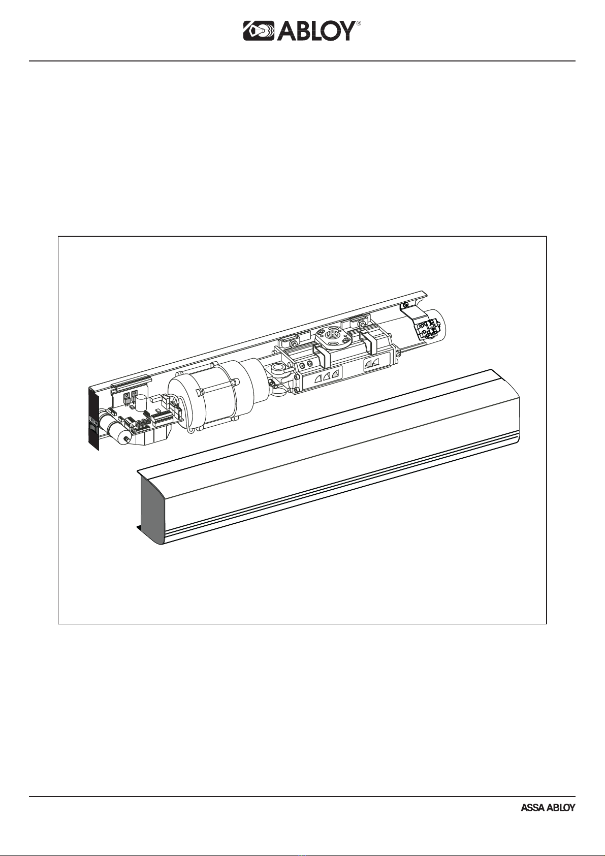
Part idendification...........................................................................................7
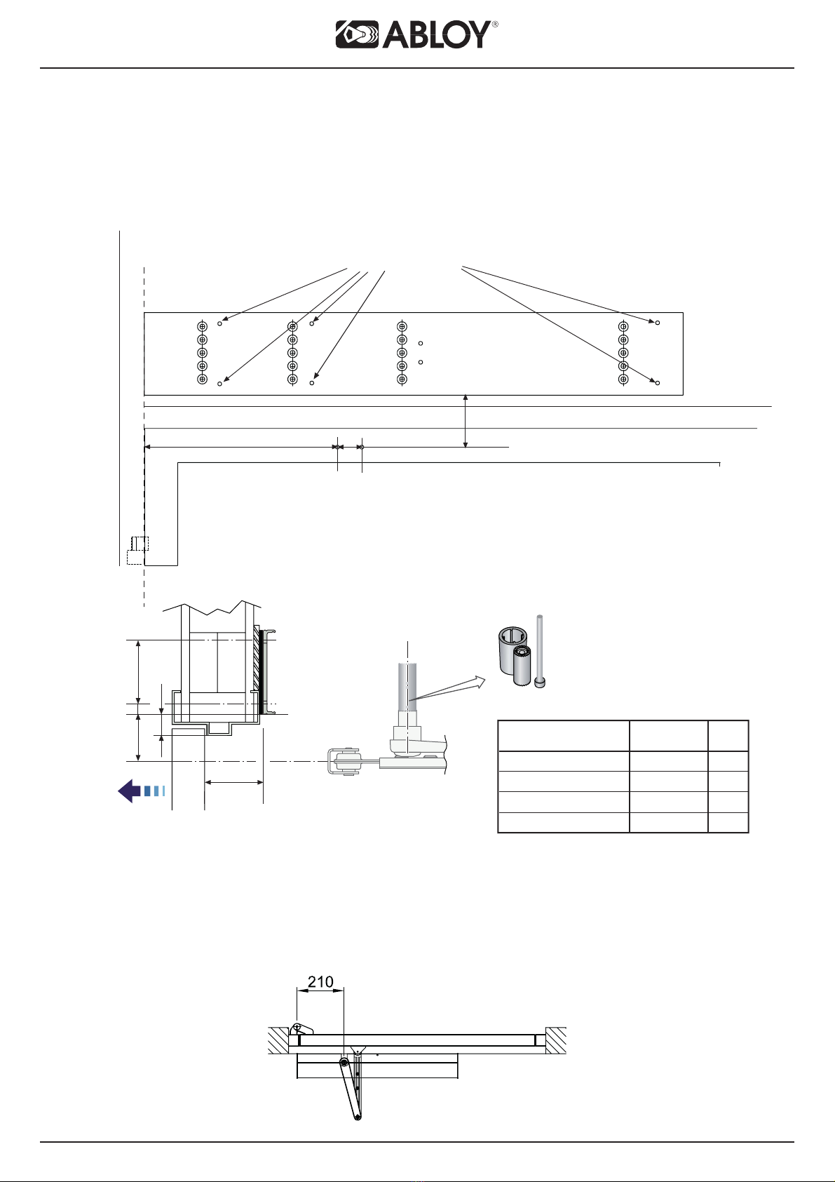
Installation..........................................................................................................8
Installing the mounting plate DB103.........................................................................9
Assembly of the operator and the standard arm DB104 to the closing side...............10
Assembly of the operator and the sliding arm DB105 to the opening side...............1
Assembly of the operator and the sliding arm DB105 to the closing side.....................14
Electrical connections.......................................................................................15
Adjustments.........................................................................................................16
A safe door..................................................................................................................18
Changing the direction of rotation ..................................................................................19
Control unit........................................................................................................................... 0
Dip -switches FS.................................................................................................
TB and TB1................................................................................................................. 4
Connection examples
Program selector PS-3A....................................................................................... 5
Kill input.................................................................................................................... 7
DA061, DA06 and DA063 microwave motion sensor..................................................... 8
DA033 elbow switch and DA039 and DA049 rotary switch................................... 9
Extension unit EXB-FI.........................................................................................................30
Connection examples extension unit EXB-FI
DA001 / DA00 safety sensor in the opening side of the door........................................31
DA001 / DA00 safety sensor in the closing side of the door.......................................3
Connection examples control unit and extension unit EXB-FI
Electric locks EL40 , EL404, EL50 ................................................................33
Program switch, motor lock and safety sensor in the opening side of the door.................34
Fire door use........................................................................................................35
Connection of double doors...........................................................................................36
Coordinator DB109...........................................................................................38
Closing side.......................................................................................39
Opening side..................................................................................................40
Push&Go DB116.....................................................................................................41
Troubleshooting...........................................................................................................................4
Accessories and spare parts...............................................................................................43

4
DB001 swing door operator EMSW - pushing
- swing door operator, pushing
- standard arm
- 50 mm extension piece
- 3 -position program switch
- cover
- extension piece for arm, reveal max. 30 mm
DB00 swing door operator EMSW - pulling
- swing door operator, pulling
- sliding arm
- 0 mm extension piece
- 3 -position program switch
- cover
DB0 0 swing door operators for double door EMSW
- swing door operator for active door
- swing door operator for passive door
- full lenght cover (from hinge line to hinge line)
- end plates for cover
NOTE! Arms and 3 -position program switch are not included in the delivery.
DB0 swing door operators for double door EMSW
- DB0 0
- full lenght mounting plate
NOTE! Arms and 3 -position program switch are not included in the delivery.
CONTENT OF DELIVERY

5
EN1154 classification.
TECHNICAL SPECIFICATIONS
·Mains power supply: 30 VAC (-10 - +10 %), 50 Hz, fuse 10 A
·Power consumption: max 30 W
·Auxliary voltage : stabilized 4 VDC, 700 mA
·Motor Fuse: 6,3 AT
·Control unit fuse: 50 mAT
·Class of protection IP 0
·Dimensions: 716 mm x 110 mm x 110 mm (Length, Depth, Height)
·Weight: 11 kg
·Operation: -15...+30°C (in dry premises)
·The automatic swing door operator must not be installed in applications where it is subjected
to water or snow.
·Maximum recommended door weight/width:
Standard arm: 50 kg / 1600 mm
Sliding arm: 100 kg / 1400 mm
·Limit switch (DB10 ): 1A, 48 VDC, NO
Note the maximum door weight in fire doors. Class 6 door closer will
close door 1 0kg / 1400 mm.
Mount a door stop to the door open position so that wind will not drive
the door against the wall, resulting in damage
Class S andard arm Sliding arm Closing
orque
Door weight[kg] Door weight[kg] [Nm]
/ width[mm] / width[mm] (0-4°)
10 / 750 9
240 / 850 13
360 / 950 60 / 950 18
480 / 1100 80 / 1100 6
5100 / 1 50 37
61 0 / 1400 54

6
OPERATION
The swing door operator works electro-hydraulically. It opens with an AC-motor that via
a hydraulic unit and an arm system transmits the power to the door leaf. The closing
power is from a coil spring. The movement of the door is controlled by limit switches and
valve screws.
Opening
When an opening impulse is received by the control unit, the motor starts and the hydraulic
unit rotates the drive shaft and arm system (door) with high speed towards open position.
Before fully open position, the speed is reduced to low speed. The door stops and the motor
rotation ceases when the selected door opening angle is reached. This open position is kept
by a hydraulic valve.
Closing
The spring closing starts when the hold open time has run out. Before fully closed position
the speed is reduced to low speed, which will be kept until the door is completely closed.
The door is kept closed by spring power.
Functions of program switch
AUTO:
The operator opens the door for the duration of the hold open time.
MAN:
Manual use.
OPEN:
The door is held permanently open.

7
PART IDENTIFICATION
T20
Parts:
1. Base plate
. Motor/Pump
3. Magnetic valve
4. Door closer
5. Drive shaft
6. Mains connection
7. Control unit
8. Program switch
9. End plate
10. Extension unit EXB-FI
11. Cover
11.
7.
4.
6.
5.
3.
1.
.
9.
8.
10.

8
INSTALLATION
Steps of installation
- Preparing installation
- Installing the mounting plate
- Mounting the operator and the arm
- Connecting the operator to mains
- Commissioning
- Testing
- Connecting impulse devices
Preparing installation
- Check the proper function of the door
- hinges
- door clearance
- Check the proper function of the lock
- lock case
- striker plate
Tools required
- Torx T8, T10, T 0 and T 5
- Metric hexagonal key 3, 4 and 6 mm
- Flatblade screwdriver, small
- Torque wrench with metric Allen socket 6 mm
Base material Minimum requirements of wall profile
Steel 5 mm
Aluminium 6 mm
Wood 50 mm
Mount a door stop to the door open position so that wind will not drive
the door against the wall, resulting in damage

9
0
37,50
0
78
198
343,50
638
716
80
INSTALLATION
Installing the mounting plate
Operator is to be installed on the transom, with the main switch located towards the hinge.
Use the mounting plate DB103 with the door operator ensuring the installation base is level
and securely fixed to a flat surface.
110

10
Frame depth 105 - 30 mm DB114 (arm extension)
Frame depth 30 - 360 mm DB115 (arm extension)
48 45
Mounting of the operator
6 pcs M6x1
Y
Assembly of the operator and the standard arm DB104 to the closing side
Adjustable hold open angle up to 1 0°.
50
17
17 37 70
37 67 100
67 87
XY
1 0
0 mm (DB106)
50 mm (DB107)
70 mm (DB108)
No extension piece
Lenght of
extension piece
C
L
80
0-105
13
X
Y

11
90°
5 Nm
90°
60
Assembly of the operator and the standard arm DB104 to the closing side

12
109 58
Y
3
Assembly of the operator and the sliding arm DB105 to the opening side
80
Y
38
A
45
3 Min. 5
Frame depth A, max 1 5 mm.
13
69
89
119
Y
139
0 mm (DB106)
50 mm (DB107)
70 mm (DB108)
C
L
Mounting of the operator
6 pcs M6x1
No extension piece
Lenght of
extension piece

13
0 V DC
24 V DC
V DC
ey Impulse
Lock 24 V DC
or
n
uter Impulse
VI Impulse
ALLTB1ANDTB2,
CLASS2SUPPLY
MAX.24V
56
78
9101
113
1214
TB2
701500
HSO
HSO
LSO
LSO
LSCLK
HSC
HSC
LSC
701448
LK
I
I
I
I
I
I
I
I
I
I
I
I
I
I
I
I
I
5 Nm
HSC
or
n
ALL
CL
56
78
910 1
113
1214
TB2
Open the door in 90 degrees angle.
Assembly of the operator and the sliding arm DB105 to the opening side

14
109 58
Y
Min. 54
Frame depth A, max 45 mm.
69
89
119
Y
136
0 mm (DB106)
50 mm (DB107)
70 mm (DB108)
80
Min.54
Y
38
A
C
L
Assembly of the operator and the sliding arm DB105 to closing side
Mounting of the operator
6 pcs M6x1
No extension piece
Lenght of
extension piece

15
N L
F1 = 50 mAT
F = 6.3ATH
30VAC 3 x 1,5 mm
No e! It is important that the hi h and low volta e cables are well
separated and fixed.
The hi h volta e cables must be routed and fixed on one side of the
drive unit by usin the enclosed cable holders and the low volta e
cables must be routed on the opposite side usin the same type of
cable holders.
ELECTRICAL CONNECTIONS
- Electrical connections should be made by a qualified electrician.
- The power plug must have an easy access.
- If a permanent connection is made unit must be equipped with an external
switch providing all pole disconnection.
- Keep the mains disconnected during installation.

16
ADJUSTMENTS
Give a short opening impulse by strapping the impulse input and adjust if necessary
as follows.
Adjustment of the opening speed
Adapt the high speed opening HSO, to the existing traffic situation. Turning clockwise
decreases the speed.
The low speed opening LSO, needs to be adjusted only if the door is extremely heavy.
Turning clockwise decreases the speed.
Note! If it is hard to obtain an even and smooth braking, the opening torque (pump pressure)
must be reduced.
Adjustment of the closing speeds
Adjust the low speed closing LSC as low as the traffic situation allows. Turning clockwise
decreases the speed.
If a higher closing speed is required, open the high speed closing valve HSC (closed from
factory).
An additional lock-kick can be obtained during the last 5° of the closing cycle by adjusting
the screw LK on the hydraulic unit. This screw is normally closed. Adjust by opening the
screw 90° and check the function. Note! Opening the screw too much may delay the opening.
Opening angle
Fine-adjust the opening angle by means of the limit switch. The limit switch is slid into a
groove in the hydraulic unit and tightened with a lock screw. By moving the limit switch
sideways, the opening angle is changed.
Note! To make the adjustment easier, the limit switch can be moved to the underside of the
hydraulic unit. Any of the grooves at the motor side of the outgoing shaft can be used.
Closing force
To comply with authority requirements or to overcome over/under pressure the closing torque
can be adjusted. The closing torque (spring force) is adjusted by means of an Allen screw
placed at the end of the spring tube. The end plate has to be dismantled. Turning the screw
clockwise increases the force. One turn equals a torque change of approx. 1 Nm ( 8 turns
from min. to max.). The door must be in open position when extremely low torque is adjusted.
Opening torque
If the closing torque (spring force) has been changed, or if the door does not open to its full
extent, the opening torque (pump pressure) must be adjusted as follows:
1. The factory set torque for DB104 is 70 Nm and for DB105 40 Nm at a door opening angle
of 0- °.
. Measure the opening torque by using a spring balance and adjust if necessary.
The torque is adjusted by means of an Allen screw placed on the pump. Turning clockwise
increases the opening torque/pump pressure. One turn equals a torque change of approx.
30 Nm.

17
HSO
LSO
LSO
HSO
LSCLK
HSC
LSC
LK
HSC
3 mm
LSO
HSO
LK F
5°
3 mm
10 mm
POCKET
BALANCE
00
22
44
66
88
1010
1212
1414
1616
1818
2020
2222
2525
F
POCKET
BALANCE
00
22
44
66
88
1010
1212
1414
1616
1818
2020
2222
2525
5°
Closing side/PUSH = 35 N
Opening side/PULL = 0 N
6 mm
mm
LSC
HSC
Closing side/PUSH = 70 N
Opening side/PULL = 40 N
ADJUSTMENTS

18
A SAFE DOOR
The safety of the door operator is controlled by basic adjustments;
operator force, speeds, and hold open times.
- The operator force is an important adjustment. A high value affects to the
safety feature and also to its sensitivity.
- High speeds increases the energy transferred in the door causing it not stop
correctly.
- With hold open times the distance from impulse device to door is preset.
1. Adjust low opening and closing speeds.
. Adjust the operators opening torque and closing force to a low setting.
3. Adjust the hold open times.
By following these basic procedures the operator is safe in operation.
Note!!! High speeds and safety is only possible by fitting of Safety sensors.
A safe door environmen needs ALWAYS a safe y sensor.
I is recommended o use safe y sensor when possible,
no only wi h high speeds.

19
1. Washer and screw
. Screw (4 pcs)
3. Bearing sleeve ( pcs)
4. Tool DB110
5. Setting lines
1
4
2
35
1. Mount the washers and screws in the drive shaft, one from each side.
. Dismantle the screws (4 pcs) from the bearing sleeves on both sides.
3. Fit the tools in the holes, one from each side. Note! Turn both bearing sleeves
simultaneously approx. 165° until the setting lines in the bearing sleeves are aligned
with the setting lines in the housing. If not done carefully, drive unit can be damaged.
4. Remount the four screws in the bearing sleeves and dismantle the washers and screws.
CHANGING THE DIRECTION OF ROTATION
The direction of rotation can changed by using tool DB110.

20
5678910 1113
12 14
Magnetic valve
Limit switch open
Home switch
Capacitor
Motor
Main supply
Led
Connection of EXB-FI
extension unit
CONTROL UNIT
Internal connections
Limit switch open
The limit switch indicates a fully open door and can be adjusted for opening angles up to
1 0º.
When the limit switch is activated the motor will stop. If the limit switch is not activated, the
motor will stop after 10 sec. If the limit switch is deactivated when the door is open, the motor
will restart to reposition the door.
The LED indicates an activated limit switch.
Contact rating: 1A, 48 V DC, normally open.
Magnetic valve
When door is open position, the magnetic valve closes and door is kept open for adjusted
hold open time.
Home limit switch
When no home switch is mounted and the limit switch is deactivated in open position, a timer
starts and after 6 sec the status will change from closing to closed door. If the optional home
switch (DB10 ) is mounted, this will indicate closed door instead of the timer.
Opening delay for lock (0-3s) is ignored as soon as home switch is not activated.
Slave delay(0,5s) is ignored as soon as home switch for the master is not activated.
Presence impulse is ignored when home switch indicates a closed door. The LED indicates
an activated home switch.
This manual suits for next models
1
Table of contents
Other Abloy Door Opening System manuals