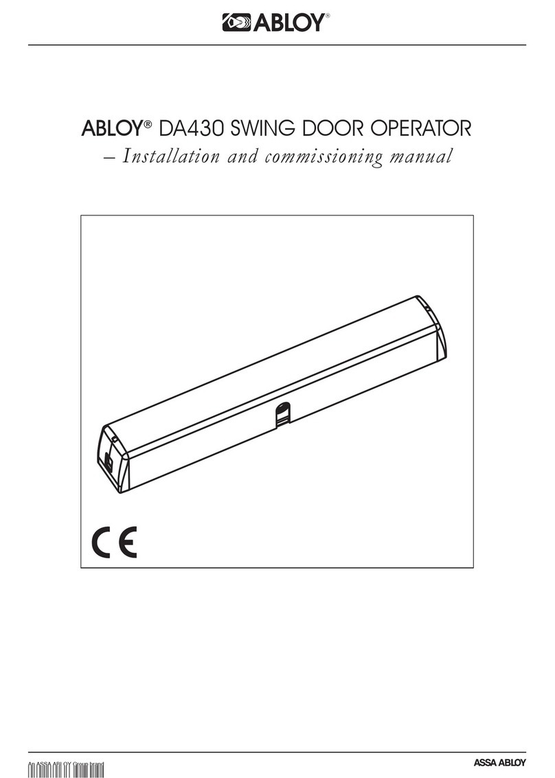
Abloy DA400 User manual

ABLOY®
DA400
Swing door operator
PROGRAM VERSION 1.5
PICOMED

CONTENTS
GENERAL
INSTALLATION
ADJUSTING DOOR MOVEMENTS
CONTROL POINTS
CONNECTIONS
BATTERY OPERATION
FIRE DOOR SYSTEM
PROGRAMMING HANDSET
CONNECTION EXAMPLES
Technical data
Construction & operation
Removal of housing
Function switches
Installation
Electrical connections
Adjusting door movements
Control points
Internal connections
External connections
Battery operation
Battery adapter
Fire door system according UL requirements
ABLOY fire door system
Programming handset
Connection examples
Connections with electric locks
1
2
3
3
4
7
8
11
18
20
22
26
27
28
29
30
31

DEAR CUSTOMER
You have acquired an electro-mechanical automatic swing door operator, the
safety of which has been proven through our research and development and
field tests. The modern Scandinavian design available in three different
colour alternatives will ensure its acceptabily in the various enviromentally
demanding applications.
ABLOY's extensive network of sales and after-sales service points will ensure
long and trouble-free service life for the automatic swing door operator.
The automatic swing door operator has been approved by the Electrical
Inspectorates of FINLAND, DENMARK, NORWAY and SWEDEN.
The installation and service of the automatic swing door operator must be
carried out in accordance with the installation instructions. Only persons who
have undertaken ABLOY product training may install and comission the
automatic swing door operator.

GENERAL INFORMATION
Approvals
Warnings
Low Voltage Directive (Finland, Sweden, Norway, Denmark)
EMC Directive (European Community)
UL (United States of America)
CSA and ULC (Canada)
Fire door use (Finland, USA, Canada)
Closing force must not exeed 178 N (40 lb) for a pedestrian application.
Closing time for last 10° (degrees) must be at least 1,5 seconds (UL requirement).
The fire adapter (see page 30) must be used in fire doors applications
in USA and Canada.
In fire door applications the operator must be equipped with battery back-up.

1
TECHNICAL DATA
The automatic swing door operator is intended for both new and existing swing
door applications, internal and opening out external doors. The automatic
swing door operator can be used in residential units, institutions, shops, public
buildings, warehouses and offices.
Operating conditions
For use in dry premises, temperature
range -10...+50 C
Stored in dry premises, temperature
range -30...+85 C
The automatic swing door operator
must not be installed in applications
where it is subjected to water or snow
o
o
Technical data
Supply voltage 115/230 V AC
50/60 Hz, Rated output 50 W
Stabilized voltage from operator to
impulse devices and electric locks
12 and 24 V DC
Enclosure class IP 20
Micro-processor control
Programmable adjustment of all door
movement functions
Operator dimensions and door
weights shown in installation drawings

CONSTRUCTION & OPERATION
2
Control unit
Direct current - motor
Pulse counter
Pulse disk
Safety clutch
The operation of the automatic swing door operator
is controlled by a microprocessor.
ABLOY
The body and the housing of the operator are manufactured from aluminium.
The body is secured to the wall or transom by four fixed bolts following the
installation of the mounting plate with the power switch side of the unit
mounted towards the hinge side of the door.
The operation of the automatic swing door operator is influenced by its
control unit, where connections for electric locking and impulse devices are
made. All control impulses must be volts free (N.O) Normally open. All the
functions of the control unit are determined by a microprocessor.
The functions of the automatic door operator, e.g. opening and closing speed,
lock-up force, and the load required by the door are programmed using the
push-buttons mounted on the control unit. The digital display indicates the
values set. Also available is a programming handset.
The control unit can also be programmed for power-assisted manual
opening; when the door is opened slightly, the operator will automatically
open it.
In the event of a power failure the swing door operator can be equipped with
a back-up battery. A flashing red LED warns when battery needs
replacement.
A safety clutch to the drive shaft protects the door operator against
mechanical damage. The clutch will slip if the door is opened by force.

REMOVAL OF HOUSING
3
SWITCHES
Program selector:
2
- position switch
= AUTOMATIC: The impulse device connected to the door
operator will open the door and close it after a preset door open
time. The hold open time can be adjusted between 0...60 s
(control points 7 or 17).
Power-assisted manual opening is also active during this period.
= The door opens and remains open. On switching to either
AUTO or MANUAL the door will close after a preset delay.
AUTO
OPEN
IO
AUTO OPEN
Warning!
Disconnect mains supply
when removing or
mounting the housing.
Remove the housing by
inserting a wide-blade
screw driver at each
end.
The automatic swing door operator is mounted
with the end to the is
located towards the hinge side of the door. When the
door operator is switched on, the red LED on the
mains switch lights up. The mains supply
should always be on to ensure that the back-up
battery is being charged.
mains switch
Switch:I=ON,0=OFF.
Disconnect mains
supply when
making electrical
connections.

INSTALLATION
4
Extension piece
Note!
6
Inspect the swing door operator against transport damage.
Test the free swinging of the door, which should open and close smoothly.
The automatic swing door operator is to be installed on the transom, with the
mains switch located towards the hinge.
For , the door operator is mounted on the stop side of the door
installing the standard arm 7281 or 7282.
For , the door operator is mounted on the hinge side of the door
installing the sliding arm 7611.
Use extension pieces for non standard applications. Maximum extension
shaft length 60 mm. Extension shafts: 10 mm, 20 mm, 60 mm.
push function
pull function
Mount a door stop to the door open position so that wind will not drive the
door against the wall, resulting in damage.
The door stop can be either floor or wall mounted.
DOOR SIZE/DOOR WEIGHTS
Standard arm
7281, 7282 for
push function
Sliding arm
7611 for pull
function
Door width max. 1 m ... max. 125 kg
Door width max. 1.15 m ... max. 100 kg
Door width max. 1.3 m ... max. 90 kg
Door width max. 1 m ... max. 80 kg
Door width max. 1.15 m ... max. 70 kg
Door width max. 1.3 m ... max. 60 kg
Sliding arm 7611
Standard arm 7281, 7282
When specifying, please take account of door surroundings
and exposure to weather conditions

INSTALLATION
Drill the installation holes as shown in the drilling diagrams.
Attach the door operator to the mounting plate with four screws M8 x 25
provided.
Use the mounting plate delivered with the door operator ensuring the installation
base is level and securely fixed. Minimum wall thickness
should be 5 mm if the door frame is of metal construction.
The door operator's frame and mounting plates are provided with wiring holes
enabiling concealed wiring.
a) Push function
drilling diagrams
- use mounting plate DA100
- frame depth max. 150 mm with standard
arm 7281 or DA140, and 150-250 mm with standard
arm 7282 or DA141
- sliding arm 7611 can be used in lightweight
doors (max. opening angle 90 )
- arms DA140 and DA141 are also provided
with inch machine screws
o
IO
90o
70
Opening angle
max. 100
o
ARM W
7281 0 - 150
7282 150 - 250
284 70
W
90°
5
EX
EX
DA100
YZY Z
Y
Z
95 60
95 60
85 5085 50
75 4075 40
65 3065 30
55 2055 20
45 1045 10
35 035 0
100
108
100
184
25
70
331.5
30
45
568
284
89
62
32.5
15

6
INSTALLATION
Drill the installation holes as shown in the drilling diagrams.
Attach the door operator to the mounting plate with four screws M8 x 25
provided.
Use the mounting plate delivered with the door operator ensuring the installation
base is level and securely fixed. Minimum wall thickness
should be 5 mm if the door frame is of metal construction.
The door operator's frame and mounting plates are provided with wiring holes
enabiling concealed wiring.
b) Pull function
drilling diagrams
- use mounting plate DA100
- use sliding arm 7611 or DA142
- minimum door width for sliding arm application
is 750 mm
- arm DA142 is also provided with inch machine
screw
IO
IOII
565
Opening angle
max. 100
o
EX
EX
MOUNTING PLATE DA100MOUNTING PLATE DA100
YZ
95 60
85 50
75 40
65 30
55 20
45 10
35 0
100 100 184
26.75
26.5
26.75
Y
535
L
108
568
20
29,5 in DA142
Z
M
PULL FUNCTIONPULL FUNCTION
FRAME DEPT DISTANCE FROM HINGE LINE MIN DOOR WIDTHFRAME DEPT DISTANCE FROM HINGE LINE MIN DOOR WIDTH
HL MH L M
0 - 150 180 7500 - 150 180 750
150 - 200 265 835150 - 200 265 835
200 - 250 300 870200 - 250 300 870
H

7
ELECTRICAL CONNECTIONS
ABLOY
2
13
115/230V AC 3x 1,5mm2
4x 0,22mm2
3x 0,22mm2
2x 0,22mm2
2x 0,22mm2
4x 0,22mm2
5x 0,22mm2
2x 0,22mm2
Safety sensor
Remote control
Push-button/Elbow switch/Pull switch
Card reader
Radars or photocells
Motor locks Microswitch keep
CARD
Mains connections:
If a permanent connection is made, the unit should be connected to a
fused unswitched 13 Amp mains spur fitted with a 2 Amp fuse.
Operator needs a grounding-type receptacle for connection to the supply.
It is very important to have the proper grounding.
To reduce the risk of electric shock, this equipment has a grounding type
plug that has a third (grounding) pin. This plug will only fit into a
grounding type outlet. If the plug does not fit into the outlet, contact a
qualified electrician to install the proper outlet. Do not change the plug in
any way
Permanent wiring shall be employed if required by local
codes
Wiring diagram:
Any impulse device with
a potential-free output
may be connected to
the door operator.
ABLOY locks and
impulse devices should
be made by using
flexible multicore cable
of a type suitable for
signal equipment. The
automatic swing door
operator supplies a
voltage to the
impulse devices and
electric locks.
12/
24VDC
Warning!
Warning!
In case of using a switch as
an impulse device other
than a conventional mat
switch, proximity indicator,
or the like the switch shall
be installed in a location
from which operation of the
door can be observed by
the person operating the
switch

8
ADJUSTMENT OF DOOR MOVEMENTS
Pulse counter
The counter has three sensors. Two count
the pulses and the disk direction, the
other senses the perimeter of the disk.
Pulse disk
A pulse disk fitted to the drive shaft is used to determine the door closed
position. This is achieved by the pulse counter calculating a series of holes
aroung the circumference of the disk, one of which is open. When the perimeter
sensor locates the edge of the notch the door operator stops the door.
Adjusting the door closed
position
1. Mount the operator and fit the arm.
When closing the door notice the direction
of rotation of the disk. Put the program
selector on position MANUAL.
2. Switch the power on. A red LED will be lit
at the end of the operator
3. Turn the disk to the closing direction
until the red led is extinguished.
It is possible to adjust the disk after this
procedure, but the red LED will not show
the position of the hole in the disk.

9
ADJUSTMENT OF THE DOOR MOVEMENTS
Selection+ S/A- Adjustment+
Error
Adjustment
OK
OK
Adjust-
ment
Error
Control unit adjustments and selections
Control unit::
When the mains supply is connected, the control unit immediately adopts the status
determined by the program selector and the opening pulses. Only the green OK
LED is lit.
Press one of the three buttons and the display will show the status of the door
operator.
Display functions and program push
buttons:
The display
program selector
comprises of two digital
displays, three LED's and three push
buttons.
The left display section shows the status
of the . When a
programme button is pressed, the digital
display lights up, indicating the status of
the program selector e.g. 0 = MANUAL,
1= AUTO or 2=OPEN.
The right-hand display section indicates
the status of opening pulses, the safety
sensor and the locking circuit.
Signal LED's
a) is lit when the mains supply
is connected to the door operator. The
normal operating status.
b) is not normally lit. The adjustment
LED is on when control point 0...28 has been
selected using the selection + button.
c) when lit indicates an error
condition has occurred.
The green OK LED
The yellow LED
The red Error LED
E1 = safety sensor fault; check the sensor connections
E3 = button error; check the sequencing (jumpers and connections)
E5 = battery fault; check the battery
E8 = Eprom error; replace the control unit
safety sensor
pulse display
Program selector
status
locking circuit
impulse inside
impulse outside
impulse outside
inhibit
signal dot
S_A

10
ADJUSTMENT OF DOOR MOVEMENTS
Selection+
a)
S/A-
b)
Adjustment+
c)
Buttons:
a) Selection+ button
This button is used to call 0...28 onto
the display. With the light on the digital
display, press the Selection+ button for at least
3 seconds enabling yellow Adjustment LED to light.
with a appears on the right-hand side
digital display to indicating the first control point.
Control points 0...28 can now be addressed by
pressing the Selection+ button. Should you wish to
reverse the control point, press the S/A- button.
b) S/A- button
This button is used to select a lower control point
number from 0...28, or to decrease the value in the
control point.
c) Adjustment+ button
When the desired control point has been selected with
the Selection+ button, pressing the Adjustment+
button validates the and flashes on the
display.
The Adjustment LED will also flash, except for a sealed
control point. disappears from the right-
hand side display.
NOTE! The control setting of sealed control points can
only be changed after first pressing the Adjustment+
button for at least 5 seconds following which the
Adjustment LED will flash.
The control setting can be increased one step at a time
by pressing the Adjustment+ button, and decreased by
the S/A- button.
When the desired control setting is shown on the
display, press the Selection+ button. This will store the
control setting in memory and the digit indicating the
number of the control point appears on the
display. The Adjustment LED will remain lit up but will
cease flashing.
control points
Digit 1 signal dot
control value
The signal dot
next
S
_
A

11
CONTROL POINTS
max. 100
o
Control points and control values
Control points are presented in numerical order 0...28. Study all the control points
to ensure the optimum possible operation of the door. Adjust the functions
ensuring the safety clutch does not slip.
Control point
n:o Control
value Description
3...60
3...60
0...60
1...10
0...15
1...10
1...10
0...60
1...10
1...10
1...10
0...10
Opening direction: Starting point of final speed
Door open position
Closing direction: Starting point of final speed
Operator's force (Sealed)
Delay time for inside impulse
Opening speed
Opening direction: Final speed (Sealed)
Outside impulse: Hold open time
Operator sensitivity (Sealed)
Closing speed
Closing direction: Final speed
Lock-up force (Sealed)
Factory
setting
40
48
10
5
5
7
5
8
7
5
4
0

Control point
n:o Control
value Description
12
CONTROL POINTS
1...8
1 or 0
0...2
0...2
0...60
0...60
1 or 0
1 or 0
0...10
0...10
1...10
0...3
1 or 0
1 or 0
0...
6553559
0...60
Safety feature sensitivity (Sealed)
Power-assisted manual opening
Power-assisted manual opening: hold open time
Selection of arm (and restoring factory settings) (Sealed)
Battery operation
Inside impulse: Hold open time
Operation of lock control relay
Closing direction: Safety feature
Hold-open force
Pressure closed before opening
Lock control relay hold time
Sequencing (Sealed)
Master (Sealed)
Function of impulse
Counter
Operating zone for safety sensor
NOTE! When the control setting has been adjusted, acknowledge with the
Selection + button to store the new values in the memory.
Factory
setting
1 or 0
Program version
4
0
1
0
8
8
0
0
0
0
2
0
0
0
45

13
The opening angle, where the operator changes from initial speed
to final speed. (1 digit = approx. 2°)
Ensure adequate angle for final speed!
The closing angle where the operator changes from initial speed
to final speed. (1 digit = approx. 2°)
The operator's force requires adjustment to suit door
weight. Use lowest possible value to ensure the smooth function
of safety feature.
Delay = 0..15 seconds. When the operator receives the opening
impulse, the lock is released immediately but the door is delayed
in opening to accommodate for the locks release..
Adjust the opening speed so that the safety feature is not activated.
Adjust the final speed in order so that the door stops at the open
position.
Hold-open time for outside impulse. Time starts when the door is in
open position. The outside impulse can be inhibited. Check page 20:
External connections
The acceleration of the door affects to smoothness of the operator
or how sharp the door reacts to e.g. wind pressure. Value 10 = fast
acceleration, Value 0 = slow acceleration.
Adjust the closing speed so that the safety feature is not activated.
Adjust the final speed so that the door stop smoothly in its
closed position.
Hold open angle. (1 digit = approx. 2°)
CONTROL POINTS

14
The operator keeps the door closed at preset force for
1 second following which this reduced to half of the preset
value. Value0=nolock-up force.
1= Standard arm, 0= Sliding arm
2= Restoring the factory settings
0= Off
1= Fire door use (closes only)
2= Full battery backup (opening & closing)
Check page 22; Battery operation
Hold open time for power-assisted manual opening.
Also in MANUAL and OPEN-mode, also for fire door use.
Hold open time for inside impulse.
0= no operation for lock relay in MANUAL-mode
1= lock control relay activates when receiving an impulse
in MANUAL-mode
Selection of safety feature operation in closing direction
0= the door stops
1= the door stops and reopens.
The hold open force drives the door for example to a
door stop.
CONTROL POINTS
The safety feature stops the door movement for 3
seconds if an obstacle is detected in the door movement
range. If the door is about to open, the operator will
attempt to open it (at intervals of 3 seconds) until the
open time has expired. If the door is about to close, the
door operator will attempt to close it five times at
intervals of 3 seconds and then five times at intervals of
15 seconds. If the obstacle is still present, the operator
will attempt to close the door at intervals of 60 seconds.
8 corresponds to minimum sensitivity.
1 = on, 0 = off.
Power-assisted manual opening will function when the
door operator is set to automatic mode.

15
The operator drives the door against the closed position for a
preset value of 1 second.
Fire doors - adjust the lock control relay hold time to a minimum.
Sequencing
1 = Opening and closing sequencing for pair of rebated doors
The master door opens first and then the slave.
The slave door closes first and then master door.
All impulses are connetcted to the master.
2 = Sequential opening (stepwise opening)
Used in two doors following each other. The first door opens
from impulse and commands the second door to open.
The opening delay of the second door is adjusted in control
point 4. Note! The inside impulse connection is not operational.
3 = Interlock controlled doors
Used in two door following each other. The first door opens
from impulse and the second door opens from impulse after
the first door is fully closed.
The bolt information is needed in connectors 10 and 11.
Master operator for double doors
0 = No operation/slave operator
1 = Master operator
Function of impulse
0 = Normal
1 = The first impulse opens the door,
second closes the door
The operator holds the door open until hold open time
expires or there is a closing impulse. Note! If hold open
time is set to 60 seconds, the operator remains open
until the second impulse is activated.
CONTROL POINTS
MASTER

16
CONTROL POINTS
The counter indicates number of openings.
The fixed obsticles in safety sensor zone can be
excluded by adjusting the area smaller than the
door open position.
Dispalys the program version.
0= DA400 Europe
1= DA400 UL (North America)
VERSION
Other manuals for DA400
1
Table of contents
Other Abloy Door Opening System manuals
Popular Door Opening System manuals by other brands

Dorex
Dorex 1901 Series installation instructions

DITEC
DITEC Entrematic ENERGY 49E Installation manual, maintenance, use

MANTION SMT
MANTION SMT WIBAT APPLIQUE installation instructions

Najm Alfarqadain
Najm Alfarqadain M-238 operation instruction

ONLEVEL
ONLEVEL Banana Slide 50 installation instructions

Sanela
Sanela SLZA 30AZ Instructions for use

Motion 4 Doors
Motion 4 Doors EvoDrive+ user manual

Assa Abloy
Assa Abloy Besam SW200i US Installation and service manual

Genie
Genie GCL OPGSX Series installation manual

ECO Schulte
ECO Schulte EF BG Assembly instruction

Chamberlain
Chamberlain K001D8398-1 Power board replacement

Excel
Excel XL8000 Series Installation