ABS Sanimat 1501S User manual

www.absgroup.com
ABS lifting station Sanimat
1030-00
15970299GB (10/2006)
Installation and Operating Instructions
GB

2 Installation and Operating InstructionsInstallation and Operating Instructions
ABS lifting station Sanimat
ABS reserves the right to alter specications due to technical developments
Contents
1 General................................................................................................................................................... 3
1.1 Application areas..................................................................................................................................... 3
1.2 Technical Data......................................................................................................................................... 3
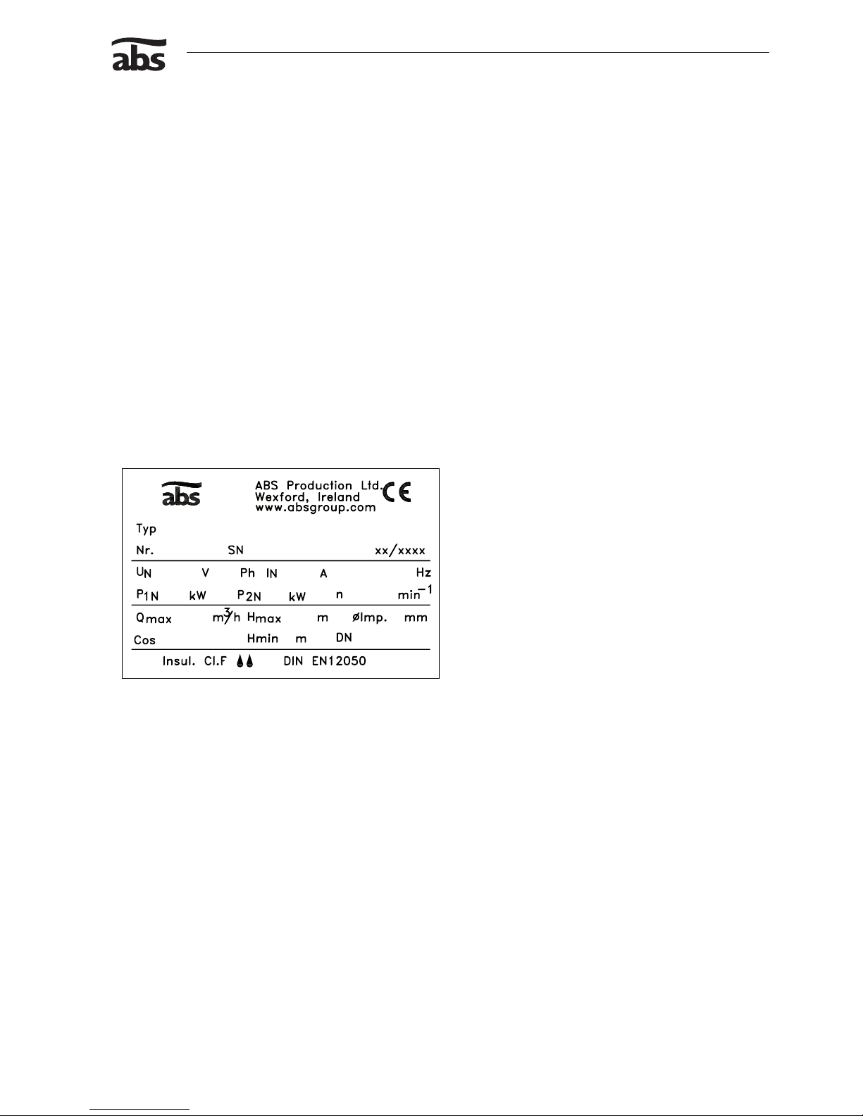
1.3 Nameplate............................................................................................................................................... 3
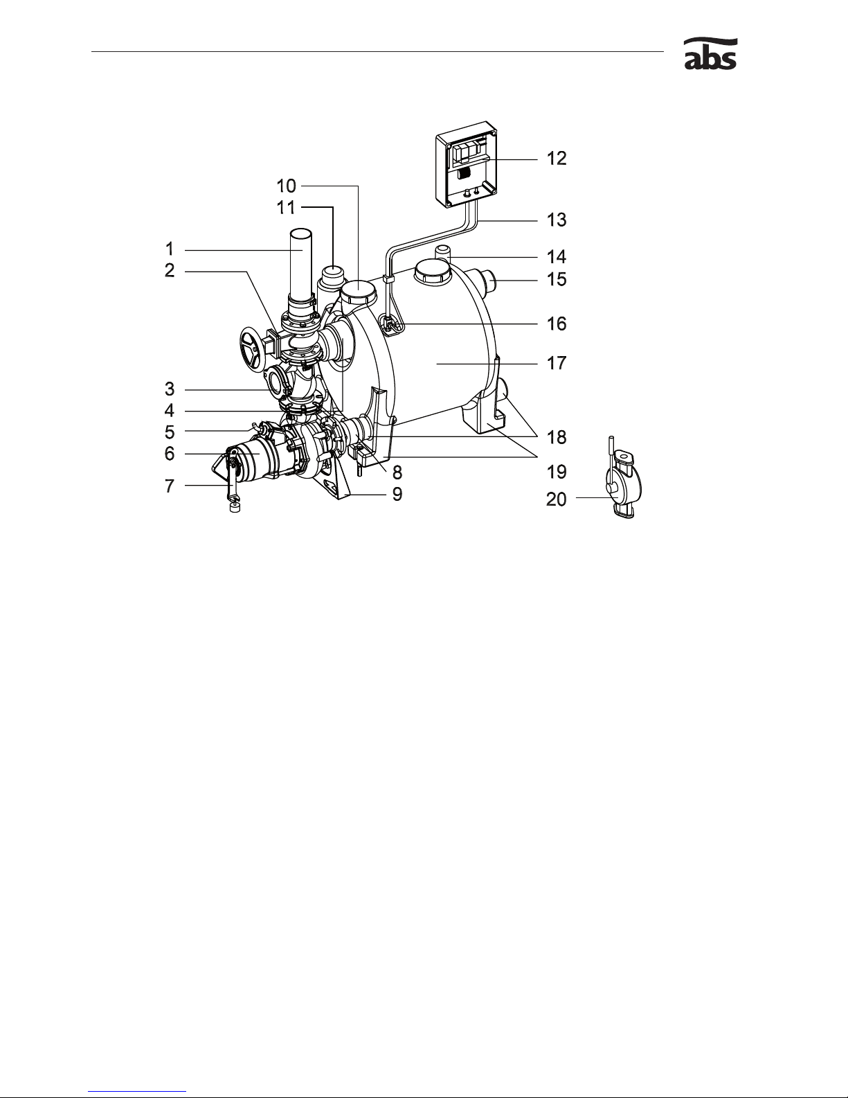
1.4 Design of the faecal lifting station ........................................................................................................... 4
1.5 Description .............................................................................................................................................. 5
2 Safety ..................................................................................................................................................... 5
3 Transport................................................................................................................................................ 5
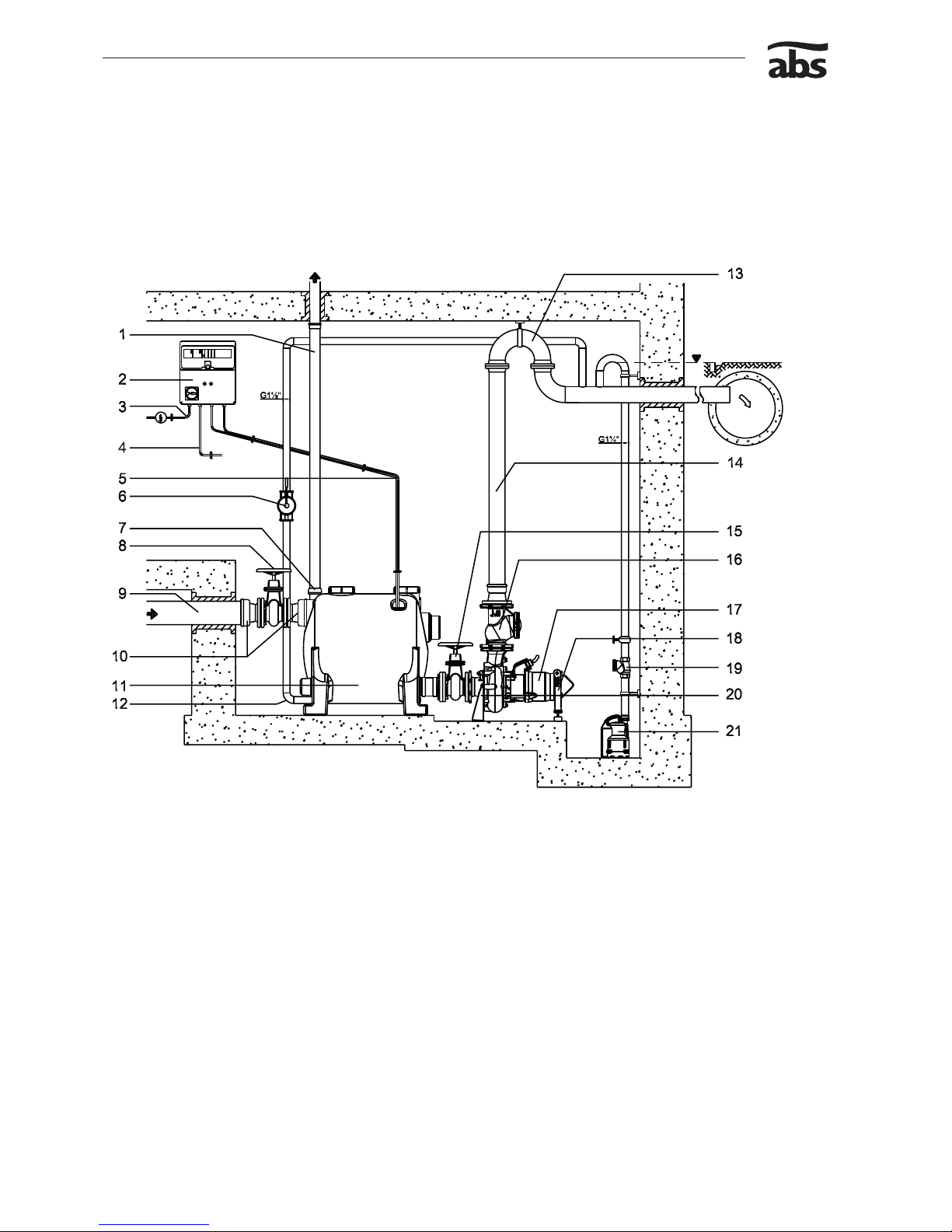
4 Mounting and Installation.....................................................................................................................6
4.1 Site requirements .................................................................................................................................... 7
4.2 Installation of the collection tank ............................................................................................................. 7
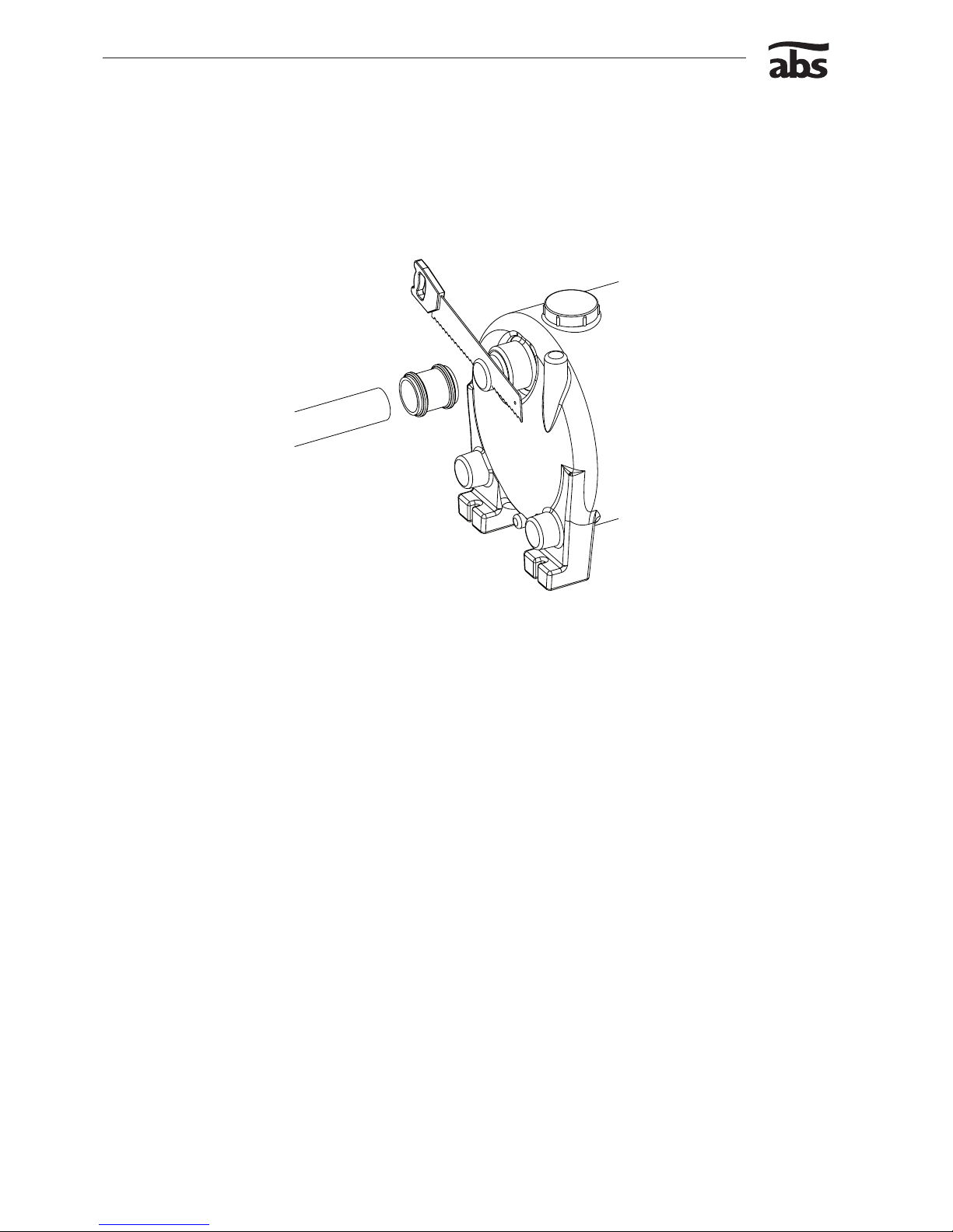
4.3 Opening of the collection tank inlet ports ................................................................................................ 8
4.4 Discharge Line ........................................................................................................................................ 8
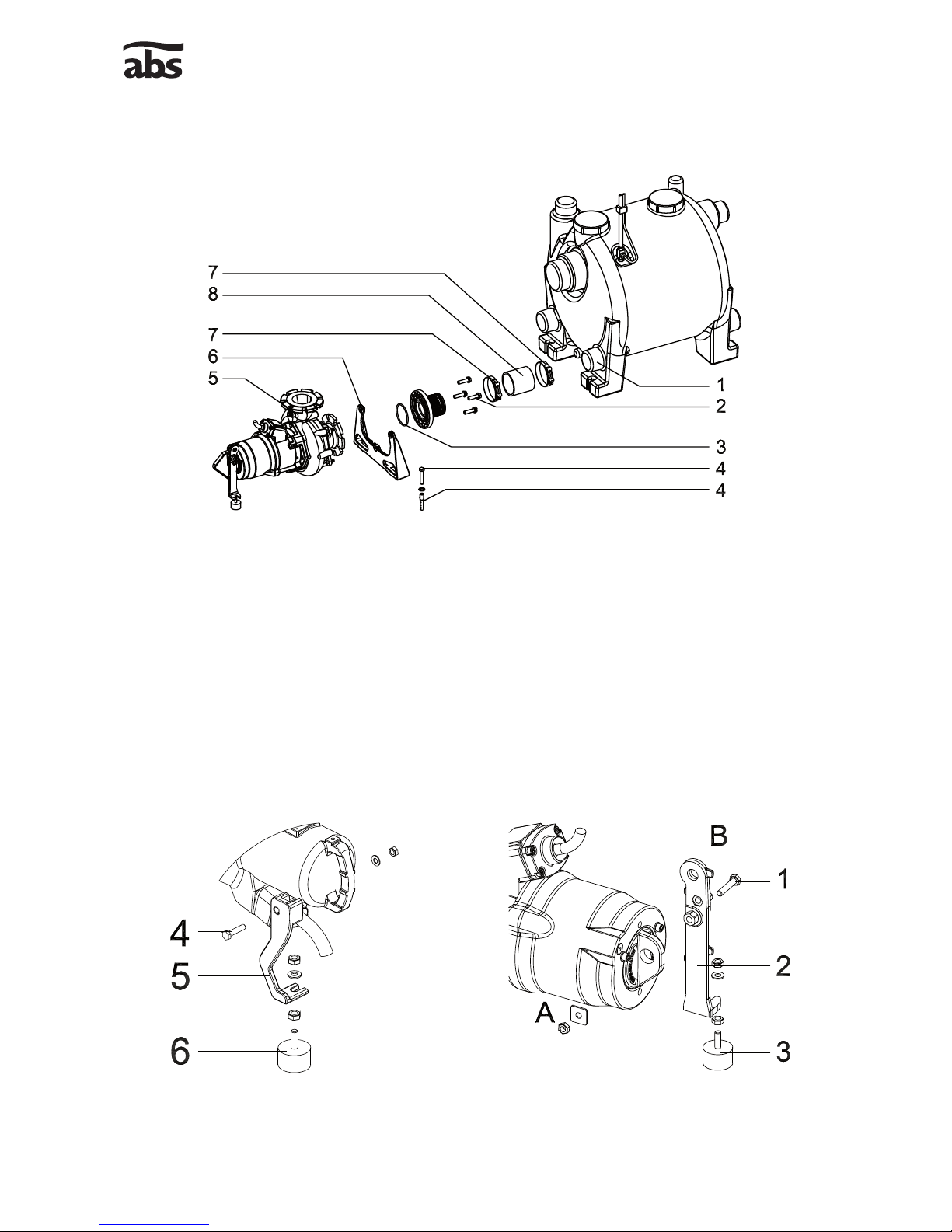
4.5 Installation of the submersible pump....................................................................................................... 9
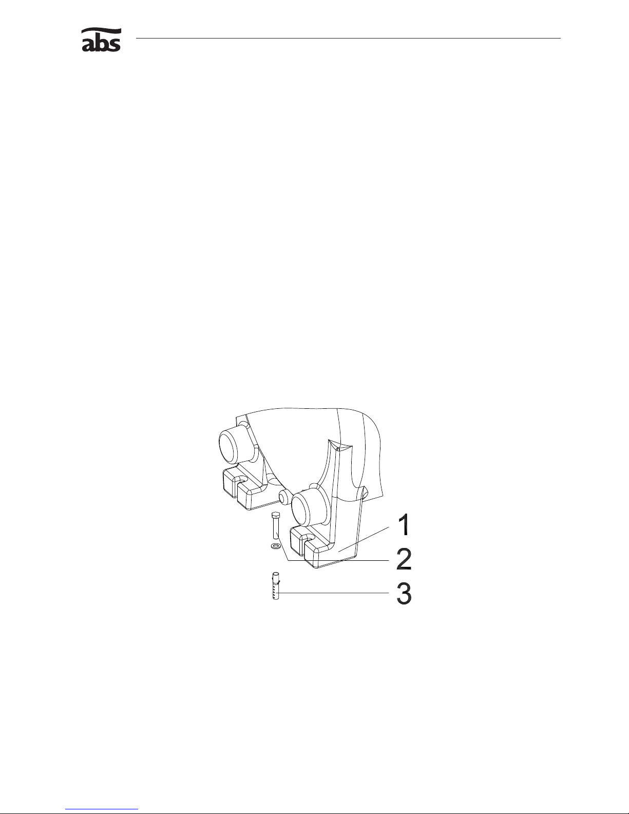
4.5.1 Mounting of the volute support................................................................................................................ 9
4.5.2 Installation of the pump head support ..................................................................................................... 9
4.6 Level Control ......................................................................................................................................... 10
4.7 Installation of the control unit ................................................................................................................ 11
4.8 Electrical Connection ............................................................................................................................ 11
4.9 Wiring Diagram ..................................................................................................................................... 12
4.10 Checking direction of rotation................................................................................................................ 13
4.11 Installation of the accessories ............................................................................................................... 13
4.11.1 Installation of the Hand Membrane Pump (wall mounted) .................................................................... 13
5 Commissioning ................................................................................................................................... 14
6 Maintenance ........................................................................................................................................ 14
6.1 Commentary on maintenance of Lifting Stations in accordance with EN 12056................................... 14
6.2 General maintenance hints ................................................................................................................... 15
6.3 Oil lling and Oil changing..................................................................................................................... 15
6.4 Cleaning of level control pipe ................................................................................................................ 15
ABS Lifting station Sanimat
1501
3702

Installation and Operating Instructions 3
ABS lifting station Sanimat
1 General
1.1 Application areas
m These lifting stations may not be used for the collection or pumping of ammable or corrosive liquids.
Efuent containing grease, petrol, or oil should only be brought to the lifting station via a separation
device.
The ood-proof faecal lifting stations of the series Sanimat 1501S to 3702S have been designed for the
pumping of sewage from locations below the sewer backwash level in accordance with EN 12056.
1.2 Technical Data
Maximum noise level ≤ 70 dB.
1.3 Nameplate
We recommend that you record the data from the original nameplate on the nameplate illustration below and
maintain it, together with your purchase receipt, as a proof for subsequent use.
Always state the pump type, item no. and serial no. in the eld “Nr” in all Communications
Legend
1003-00
Type Pump type
Nr./SN Item No./Serial No.
xx/xxxx Production date (Week/Year)
UN Rated Voltage V
IN Rated Current A
Frequency Hz
P1N Rated Input Power kW
P2N Rated Output Power kW
nSpeed min-1
Qmax Max. Flow m3/h
Hmax Max. Head m
Ø Imp. Impeller diameter mm
DN Discharge diameter mm
SS Water pressure tight
IP 68 Protection type
Figure 1 Nameplate Standard Version

4 Installation and Operating Instructions
ABS lifting station Sanimat
1.4 Design of the faecal lifting station
1031-00
Figure 2 Design of the lifting station
Discharge line
Shut-off valve
Ball-type non-return valve
Inow port DN 150/200, height 600 mm
Motor connection cable
Submersible pump
Pump head support
Flexible connector between collection tank and submersible pump - is noise absorbing
Volute support
Inspection opening, above Sanimat 3701 2-off
Inow ports DN 100/150
Controls
Control line for the level control
Vent port
Inow ports ON 100/150, height 700 mm
Submerged tube for the level control
Collection tank
Pump connection port
Collection tank legs for fastening and for prevention of oating
Hand membrane pump G 1 1/2”
NOTE The positions numbers 1-4 and 23 are not supplied as standard. The hand membrane
pump should not be fastened on to the collection tank.
1.
2.
3.
4.
5.
6.
7.
8.
9.
10.
11.
12.
13.
14.
15.
16.
17.
18.
19.
20.

Installation and Operating Instructions 5
ABS lifting station Sanimat
1.5 Description
The ood-proof sewage lifting station Sanimat 1501S to 3702S are made up of a gas and odour-tight synthetic
collection tank complying with DIN 19760 and 12050-1 with either 1 or 2 submersible sewage pumps, together
with a control unit and level control system. The collection tank is tted with a number of inow ports. The unit
is supplied from the factory with all inlet ports closed off. The inlet ports of dimensions DN 100/150 and 200 are
located at various heights and can be opened up as required.
Depending on the size of the sewage lifting station, submersible pumps of the types AS S17/2 and S26/2 as
well as pumps from the AFP series M15/4 to M60/4 can be supplied. All motors comply with Insulation Class F
(155 °C) and Protection Type IP 68. The motor shaft is supported in lubricated-for-life ball bearings. The shaft
sealing on the motor side is carried out by a lip seal, while sealing at the liquid side is carried out by means of a
high quality silicon carbide mechanical seal. The submersible pumps M15/4 to M60/4 have been supplied with
thermal sensors in the stator which switch off the motors in the event of overheating, together with a Dl-system
of moisture protection for the monitoring of the mechanical seal.
The hydraulic section is supplied with ContraBlock system, and spiral bottom plate with waved shearing inlet,
open ABS channel type impeller and volute. All hydraulic parts have been manufactured from Cast Iron (GG
25).
The sewage entering by the inlet port is collected in the odour-tight collection tank.
When a predetermined liquid level is reached, then the automatic level control system switches on the
submersible pump and switches it off again when the tank is empty.
In the case of twin pumping stations the starting sequence of pumps is reversed at each starting operation. If
level 2 is reached, then both submersible pumps work in parallel.
The automatic level control system functions as an electro-pneumatic control system based on the forced air
bubbling principle, by which compressed air is continually pumped via the submerged tube into the liquid in the
collection tank. The counter pressure caused by this is dependent on the liquid level present and operates a
membrane switch in the control system by means of the control line (plastic hose).
Units supplied with one pump can be retrotted with a second pump.
2 Safety
The general and specic health and safety hints are described in detail in the separate booklet Safety Hints. If
anything is not clear or you have any questions as to safety make certain to contact the manufacturer ABS.
3 Transport
m During transport the unit should not be dropped or thrown.
c The unit should never be raised or lowered by the Power cable.
m Any hoist used must be adequately dimensioned for the weight of the unit.
All relevant safety regulators as well as general good technical practice must be complied with.

6 Installation and Operating Instructions
ABS lifting station Sanimat
4 Mounting and Installation
NOTE We recommend that original ABS installation accessories be used for mounting and
installation of the unit
mParticular attention must be paid to the safety regulations covering work in closed areas as well as
good general technical practices.
1032-00
Figure 3 Installation example
Legend
1Vent Pipe (DN ≥70) above roof level 12 Hand membrane pump connection
2 Control unit with level control system 13 Backwash loop with lowest point above the backwash level
3Power supply 14 Discharge line (DN100)
4 Motor cable 15 Gate valve
5 Twin control line for level control system 16 Non return valve
6Hand membrane pump 17 ABS submersible sewage pump
7Push on sleeve 18 Pump head support
8 Gate valve 19 Seperate non return valve
9Sewage inow DN150 20 Volute support
10 Connection piece (push on piece) 21 Pump sump with dewatering pump (Robusta - Coronada)
11 Sanimat collection tank

Installation and Operating Instructions 7
ABS lifting station Sanimat
4.1 Site requirements
The rooms in which lifting stations are installed must be of adequate dimensions so that beside and over all
control elements or items where maintenance might be required a working area of at least 60 cm width or height
is available.
Electrical supply to suit the submersible pumps being used.
NOTE Fusing, cable cross-section and voltage drop of the power line must comply with
DIN/EN and the relevant electricity supply board regulations.
Any openings required in walls or ceilings for discharge, vent or inlet lines, must be of adequate dimensions so
that the openings used can be sealed off using noise absorbing materials.
The inlet lines must be laid in such a manner that there is a continuous fall of the prescribed magnitude to the
inlet ports of the collection tank.
NOTE When installing lifting stations the noise protection regulations in buildings to DIN
4109 should be observed.
4.2 Installation of the collection tank
Determine the installation location and set-up the tank so that it is on level ground and horizontal in all
directions.
Secure the collection tank against movement or oating with the aid of plugs (3) hex screws (2) and washers (2).
ATTENTION Provide also for later positioning of the submersible pumps. The submersible pumps
should be installed on the ground at the same level as the collection tank.
ATTENTION Do not over-tighten hex screw (2), or the collection tank (1) may be damaged.
1033-00
Figure 4 Bolting down of the collection tank
NOTE Hexagon head wood screw 10 x 130 dowel size 12 (not supplied)

8 Installation and Operating Instructions
ABS lifting station Sanimat
4.3 Opening of the collection tank inlet ports
Only open inlet posts that are to be used. Saw off as little as possible so that as much material as possible is
left for the plug connection.
File down sharp edge inside and outside.
ATTENTION Thepumpconnectionportsshouldnotbeusedasinowports.Connectamaximum
of 2 submersible pumps per tank.
1034-00
Figure 5 Opening the connections on the collection tank
4.4 Discharge Line
The discharge line must be installed in compliance with the relevant regulations.
DIN 1986/100 and EN 12056 applies in particular to the following:
The discharge line should be tted with a backwash loop (180° bend) located above the backwash level and
should then ow by gravity into the collection line or sewer.
The discharge line should not be connected to a down pipe.
No other inows or discharge lines should be connected to this discharge line.
ATTENTION The discharge line should be installed so that it is not affected by frost.
The vent line is connected by means of a push-on sleeve to the vertical outlet at the top of the collection tank.
It should be of constant cross-section (min. DN 70) and should have a continuous rise to above roof level.
-
-
-

Installation and Operating Instructions 9
ABS lifting station Sanimat
4.5 Installation of the submersible pump
4.5.1 Mounting of the volute support
1035-00
Figure 6 Mounting of volute support
ATTENTION The area where the pump stands should be smooth and level. The distance from the
centre line of the discharge port to the centre line of the discharge port comprises
460mm in the case of twin pumping stations.
Fit exible connection (8) with clamp (7) to the pump connection port of the collection tank (1).
Press the volute support (6) into the exible connector (8) and mark the position of the volute support (6) on the
oor.
Remove volute support (6). Drill plug holes and t plugs (4).
Press clamp (7) on to the exible connector, locate the volute support in position and tighten clamp (7) (x
screws (4) and washers.
Locate submersible pump (5) and seal (3) at the volute support (6) and fasten using hex bolts and nuts.
4.5.2 Installation of the pump head support
1047-00
1048-00
Figure 7 Fitting of head support AS S17 - S26 Figure 8 Fitting of head support AFP M15 - M60

10 Installation and Operating Instructions
ABS lifting station Sanimat
Submersible pumps AFP M15 ,M22 ,M30 , M40 and M60
Locate vibration damper (3) at the pump head support (2).
Fit the pump head support through ”Eyelet A” at the pump head.
Adjust the vibration damper (3) so that the rubber support rests on the ground and x the vibration damper (3) in
position using hex nuts and washers.
Submersible pumps AFP M40 and M60
Locate vibration damper (3) at the pump head support (2).
The pump head support (2) is rotated by 180° and tted via “Eyelet B” as shown in Figure 8.
Set the vibration damper (3) so that the rubber support rests on the ground, and x the vibration damper (3) in
position using hex nuts and washers.
Submersible pump AS S17 & S26
Place the vibration damper (6) at the pump head support.
Screw the pump head support (5) into the pump head using socket head screw (4).
Adjust the vibration damper (6) in such a manner that the rubber support rests on the ground and x the
vibration damper (6) in position using hex nuts and washers.
4.6 Level Control
The level control is a pneumatic system with submerged tube and control pipe (plastic hose) to the control unit.
The submerged tube is permanently installed in the collection tank. The required switching and control devices
are installed in the control unit.
1085-00
Figure 9 Installation of the control pipe
1 Control unit 5 Spigot nut
2 Connection nipple 6 Submerged tube nut SW 36
3 Twin control line 7 Submerged tube
4 T-connection piece 8 Tank
ATTENTION Thecontrolunititself(1)shouldbeinstalledabovepossibleoodlevelinsucha
manner that the control line (3) has a continuous rise to it.

Installation and Operating Instructions 11
ABS lifting station Sanimat
Control line (3) has a continuous rise as shown in Figure 9.
The control line should be shortened where necessary, pushed on to the hose nozzle of the submerged tube
screw connector (5).
The submerged tube screw connector (5) is prevented from turning by using an open ended spanner SW 13
and a spigot nut (4) is fully tightened.
ATTENTION Thesubmergedtubexingscrew(5)shouldnotbetwisted.
4.7 Installation of the control unit
ATTENTION Thecontrolunitshouldbettedabovepossibleoodlevelinawellventilatedroom
andinaneasilyaccessibleposition.ProtectionClassofthecontrolunitIP54.
The control unit should be secured at all xing points. The xing holes are accessible after unscrewing the
lower housing cover.
ATTENTION Do not drill through the housing of the control unit itself.
NOTE The mounting location of the control unit should be chosen in such a manner that the
control line rises in a continuous manner to the control unit. The control line must not
be kinked.
NOTE A number of different control box models exist. Please check the wiring diagram/
instruction manual in the control box.
4.8 Electrical Connection
c Before commissioning an expert should check that one of the necessary electrical protective devices
is available. Earthing, neutral, earth leakage circuit breakers, etc. must comply with the regulations
of the local electricity supply authority and a qualied person should check that these are in perfect
order.
ATTENTION The power supply system on site must comply with VDE or other local regulations
with regard to cross-sectional area and maximum voltage drop. The voltage stated on
the nameplate of the pump must correspond to that of the mains
The power supply cable must be protected by an adequately dimensioned slow-blow fuse corresponding to the
rated power of the pump.
cThe incoming power supply as well as the connection of the pump itself to the terminals on the control
panel must comply with the circuit diagram of the control panel as well as the motor connection
diagrams and must be carried out by a qualied person.
All relevant safety regulators as well as general good technical practice must be complied with.
NOTE The overload relay in the control unit has been correctly set at the factory.
NOTE Please consult your electrician.

12 Installation and Operating Instructions
ABS lifting station Sanimat
4.9 Wiring Diagram
Three Phase Single Phase
1013-00
1016-00
Figure 10 Three Phase Wiring Figure 11 Single Phase Wiring
1014-00
1017-00
Figure 12 Three Phase Wiring with Temperature Limiter Figure 13 Single Phase Wiring with Temperature Limiter
1015-00
1018-00
Figure 14 Three Phase Wiring with Temperature Limiter &
DI
Figure 15 Single Phase Wiring with Temperature Limiter &
DI
1021-00
Figure 16 Three Phase Wiring with Temperature Limiter &
DI
U1, V1, W1, U2, V2, W2 = Live br = Brown
PE = Earth F1/FO = Thermal sensor
Gr/Yel =Green/Yellow R = Run
blk = Black S = Start
bl = Blue C = Neutral (common)
Di = Seal monitor

Installation and Operating Instructions 13
ABS lifting station Sanimat
4.10 Checking direction of rotation
m The safety hints in the previous sections must be observed!
When three phase units are being commissioned for the rst time and also when used on a new site, the
direction of rotation must be carefully checked by a qualied person.
c The direction of rotation should only be altered by a qualied person.
ATTENTION The following characteristics of a submersible pump indicate a probable incorrect
direction of rotation.
Submersible pump runs unevenly and vibrates strongly.
Submersible pump does not achieve full output and the emptying times for the collection tank are too long.
The submersible pump makes unusual running noises.
4.11 Installation of the accessories
4.11.1 Installation of the Hand Membrane Pump (wall mounted)
1086-00
Figure 17 Installation of hand membrane pump
ATTENTION The discharge line (1) from the hand membrane pump must be installed
independently of the discharge line of the ABS submersible sewage pump, and
likewise must be provided with an anti-siphon loop located above the sewer
backwash level. The discharge lines must be brought to a location after the anti-
siphon loop.
Determine a xing location for the hand membrane pump, which is easily accessible and fasten using plugs (3)
and screws (7).
Open the connection port (8) on the collection tank in accordance with Figure 5 using a saw.
Bring the pipe line (6) from the hand membrane pump to the collection tank and connect to the outlet port (8)
chosen with the aid of exible junction piece (4) including clamps.
ATTENTION The hand membrane pump should never be fastened to the collection tank.

14 Installation and Operating Instructions
ABS lifting station Sanimat
5 Commissioning
m The safety hints in the previous sections must be observed!
Before commissioning the unit should be checked and a functional test carried out. Particular attention should
be paid to the following:
Have the electrical connections been carried out in accordance with regulations?
Is the direction of rotation correct - even if run via an emergency generator?
Was the control line (plastic hose) laid in such a manner that it has a continuous rise?
Was the collection tank secured against oating?
Has venting been installed in accordance with the regulations?
ATTENTION Before commissioning the collection tank should be cleaned of any large particles
andlledwithwater.Ifthecontrolline(plastichose)wasconnectedtothe
submerged tube with the tank already full, then the collection tank must be fully
emptied once by activation of the selector switch “Hand”. After commissioning the
faecal lifting station is normally operated with the selector switch in position “Auto”.
6 Maintenance
c Before commencing any maintenance work the unit should be completely disconnected from the
mains by a qualied person and care should be taken that it cannot be inadvertently switched back on.
m When carrying out any repair or maintenance work, the safety regulations covering work in enclosed
areas of sewage installations as well as good general technical pratices should be followed.
NOTE The maintenance hints given here are not designed for “do-it-yourself” repairs as
special technical knowledge is required.
NOTE A maintenance contract with our works service department will guarantee you the
best technical service under all circumstances.
6.1 Commentary on maintenance of Lifting Stations in accordance with EN 12056.
It is recommended that the lifting station be inspected monthly and its function checked.
In accordance with EN regulations, the lifting station should be maintained by a qualied person at the following
intervals:
in commercial premises - every three months.
in apartment blocks - every six months.
in a single family home - once a year.
In addition we recommend that a maintenance contract be taken out with a qualied company.
-
-
-
-
-
-
-
-
-

Installation and Operating Instructions 15
ABS lifting station Sanimat
6.2 General maintenance hints
ABS lifting stations are reliable quality products each being subjected to careful nal inspection. Lubricated-for-
life ball bearings together with monitoring devices ensure optimum pump reliability provided that the pump has
been connected and operated in accordance with the operating instructions.
Should, nevertheless, a malfunction occur, do not improvise but ask your ABS customer service department for
assistance.
This applies particularly if the unit is continually switched off by the current overload in the control panel, by the
thermal sensors of the thermo-control system or by the seal monitoring system (DI).
Regular inspection and care is recommended to ensure a long service life.
NOTE The ABS service organisation would be pleased to advise you on any applications
you may have and to assist you in solving your pumping problems.
NOTE The ABS warranty conditions are only valid provided that any repair work has been
carried out in ABS approved workshop and where original ABS spare parts have
been used.
6.3 OilllingandOilchanging
Waste oil must be disposed of in the proper manner.
6.4 Cleaning of level control pipe
It is recommended that the level control pipe be examined monthly to ensure that no build up of solids occurs
inside the pipe, thus preventing accurate level control of the lifting station. Build-up of solids inside the pipe can
cause continuos pumping, no pumping or inaccurate switching levels. The pipe can be pulled out of the tank
and cleaned, rinsed and replaced. It should be greased as it is put back in.

ABS Production Wexford Ltd., Clonard Road, Wexford, Ireland
Tel. +353 53 91 63 200 Fax +353 53 91 42335. www.absgroup.com
This manual suits for next models
1
Table of contents