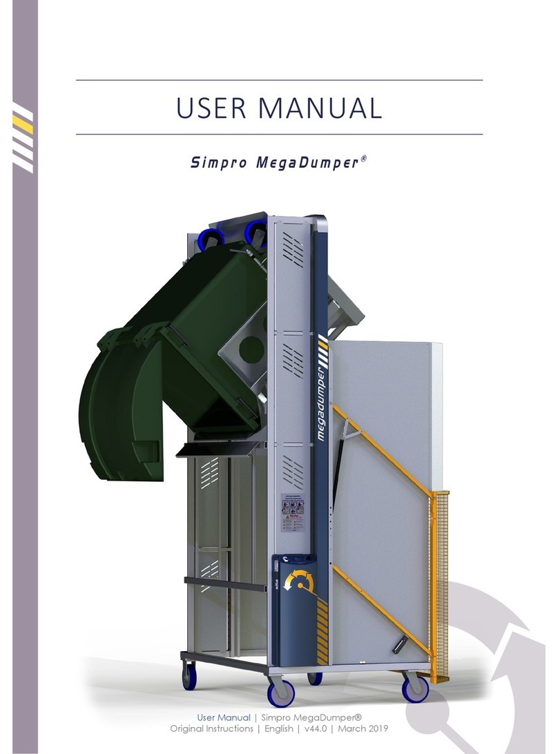
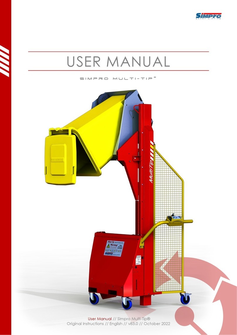
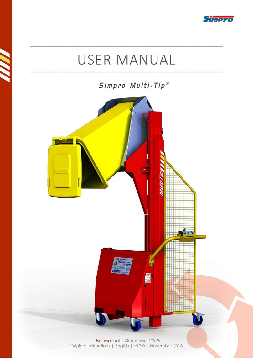
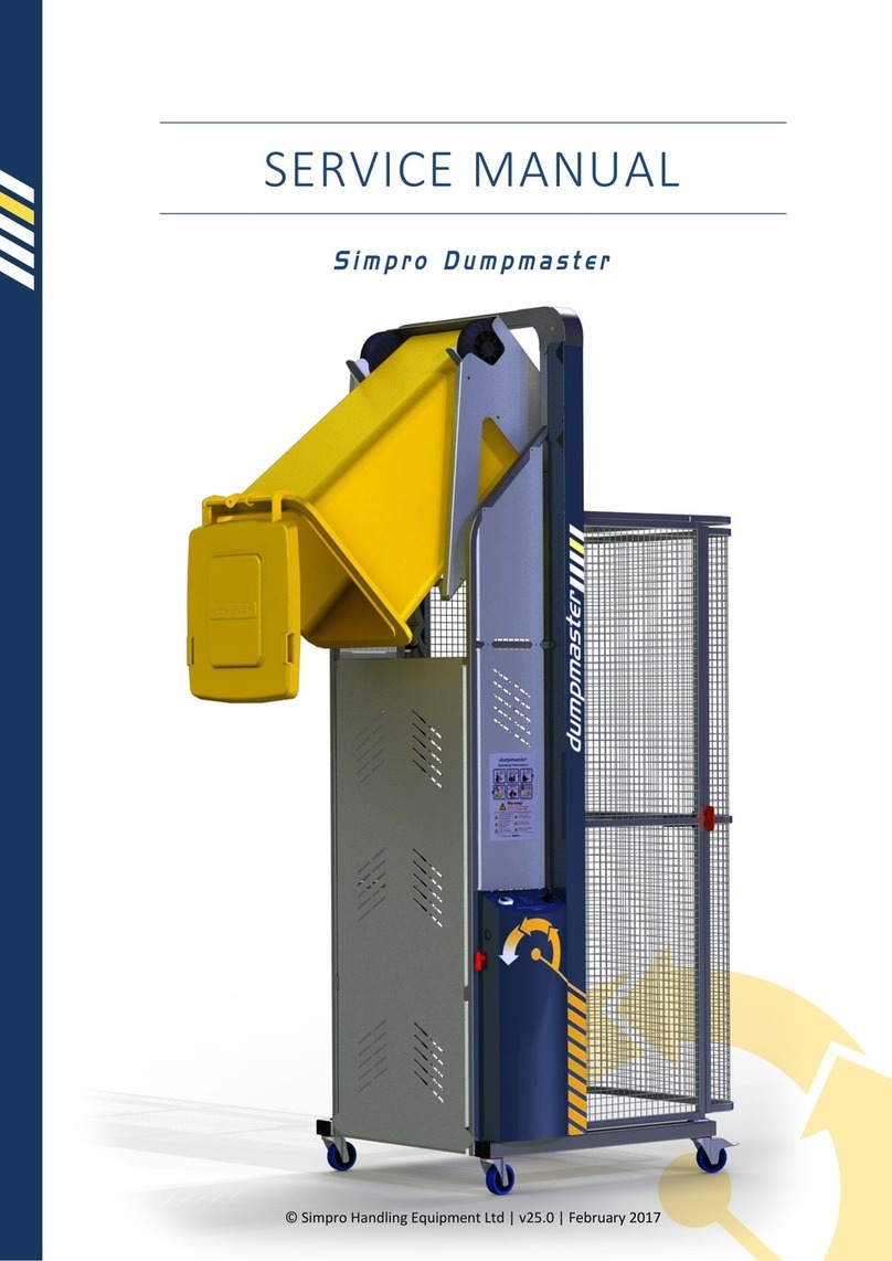
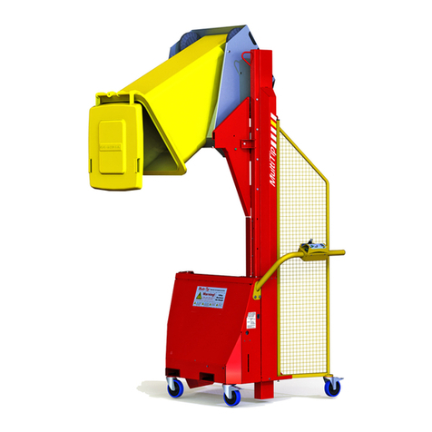
Simpro Multi-Tip 1600 User manual

© Simpro Handling Equipment Ltd | v40.0 | June 2018
SERVICE MANUAL
Simpro Multi-Tip


Service Manual | Simpro Multi-Tip | v40.0 | June 2018 | Page 2
Copyright ©2018 Simpro Handling Equipment Limited. All rights reserved.
No part of this publication may be copied or distributed in any form without permission from the copyright holder.

Contents
1 General Overview .........................................................................................................................5
2 Layout of Parts..............................................................................................................................6
3 Troubleshooting Guide .................................................................................................................7
4 Electrical System...........................................................................................................................8
4.1 General Description...................................................................................................................8
4.2 Wiring and Circuit Diagrams......................................................................................................8
4.3 Battery.......................................................................................................................................9
Removal and Refitting..............................................................................................9
Testing...................................................................................................................... 9
Care .......................................................................................................................... 9
Replacement ............................................................................................................9
4.4 Battery Isolator........................................................................................................................10
4.5 Battery Charger .......................................................................................................................10
Testing.................................................................................................................... 10
Removal and Refitting............................................................................................10
4.6 Motor Relay.............................................................................................................................11
Testing.................................................................................................................... 11
Removal and Refitting............................................................................................11
4.7 Lowering Valve Solenoid .........................................................................................................12
Testing.................................................................................................................... 12
Removal and Refitting............................................................................................12
4.8 Control Switches......................................................................................................................13
Removal and Refitting............................................................................................13
4.9 12v DC Electric Motor..............................................................................................................13
Removal and Refitting............................................................................................13
5 Hydraulic Powerpack ..................................................................................................................14
5.1 General Description.................................................................................................................14
5.2 Removal and Refitting .............................................................................................................14
5.3 Lowering Valve ........................................................................................................................15
Removal and Refitting............................................................................................15
5.4 Pressure Relief Valve ...............................................................................................................15

Service Manual | Simpro Multi-Tip | v40.0 | June 2018 | Page 4
Adjustment.............................................................................................................16
5.5 Check Valve .............................................................................................................................16
6 Hydraulic Ram.............................................................................................................................17
6.1 General Description.................................................................................................................17
6.2 Removal and Refitting .............................................................................................................17
6.3 Dismantling and Servicing .......................................................................................................17
6.4 Hose-burst Valve (if fitted) ......................................................................................................18
6.5 Ram-end Roller Replacement..................................................................................................18
7 Bin Cradle....................................................................................................................................19
7.1 General Description.................................................................................................................19
7.2 Removal and Refitting .............................................................................................................19
7.3 Cradle Jamming .......................................................................................................................20
Cradle jams at top of cycle..................................................................................... 20
Cradle jams while partway lowered.......................................................................20
8 General .......................................................................................................................................21
8.1 Cradle Carrier ..........................................................................................................................21
8.2 Mast Blocks .............................................................................................................................22
Removal and Refitting............................................................................................22
8.3 Gas Strut..................................................................................................................................22
8.4 Lifting Chain.............................................................................................................................22
Removal and Refitting............................................................................................22
8.5 Tipping Guide Gate Flap ..........................................................................................................23
8.6 Tipping Guide Frame ...............................................................................................................23
Adjustment.............................................................................................................23
8.7 Castor Wheels .........................................................................................................................23
9 Spare Parts Guide .......................................................................................................................24

1General Overview
The lifting power for Multi-Tip tippers comes from a hydraulic power pack, normally battery-
powered but may be mains-powered (refer to separate booklet for service of mains-powered
machines). When the “Raise” button is pressed, the motor runs and hydraulic oil is forced under
pressure into the lift ram, causing it to extend. The ram has a roller on the end; as it extends, a
chain is pulled up around the roller, which lifts the bin cradle.
When the “Down” button is pressed, a solenoid valve opens and the hydraulic oil flows back into
the tank at a controlled rate. The bin and cradle are not powered down –they come down by
gravity alone. The whole action is smooth and efficient, and can handle very heavy bins
continuously with little or no maintenance.

Service Manual | Simpro Multi-Tip | v40.0 | June 2018 | Page 6
2Layout of Parts

3Troubleshooting Guide
Issue
Possible Cause
Action / Reference
Lift motor does
not run when the
Raise and Safety
buttons are
pressed
Battery Discharged
Refer to section 4.3 or 4.5
Battery Isolator
turned off
Turn isolator switch on. Refer to section 4.4
Faulty motor relay or
contactor
Refer to section 4.6
Faulty control switch
or wiring
Refer to section 4.8
Faulty motor
Refer to section 4.9
Blown fuse
Replace blown fuse
Lift motor runs
but the cradle
does not lift
‘Lower’ button stuck
on
Refer to section 4.8
Foreign matter in the
lowering valve
Refer to section 4.7
Bin too heavy or
pressure-relief valve
adjusted incorrectly
Refer to section 5.4
Oil level too low
Locate and rectify source of oil leak before topping up oil
reservoir
The cradle won't
come down from
the top
Lack of lubrication
As the arms come down by gravity alone, the frame must
be able to move freely. Lubricate with a silicon spray or dry
lubricant. Do not use grease or oil.
Gas strut bent or
damaged
Contact Simpro to arrange replacement.
Lifting chain rusty or
seized
Refer to section 8.4
Lowering solenoid
valve sticking
Refer to section 5.3
Lowering solenoid
coil malfunction
Refer to section 4.7
‘Lower’ button
malfunction
Refer to section 4.8
The cradle jams
partway down
Mast bent or
damaged
Contact Simpro to arrange repair.
Tipping guide flap not
working properly, or
trigger pin out of
alignment
Refer to section 8.6

Service Manual | Simpro Multi-Tip | v40.0 | June 2018 | Page 8
4Electrical System
4.1 General Description
The motor relay and lowering coil are connected to negative all the time, and the positive is
switched in the handle controls. The positive signal goes through the Key switch, then the Safety
button switch, and finally the Raise and Lower switches. There are no limit switches –the operator
simply releases the buttons when the cradle is fully raised or lowered.
The Control switches are rated to IP 66 and the motor is IP55.
Always keep the charging socket dry. If it gets wet, it should be dried before the lead is plugged in.
4.2 Wiring and Circuit Diagrams

4.3 Battery
Battery-powered machines normally have a sealed 21 amp-hour gel battery mounted on a bracket
at the right-hand side of the main box. Depending on the amount of usage, the battery should
have a life of 2 - 3 years; if used continuously or not maintained correctly, the life may be reduced.
A battery with larger capacity can be fitted if required. This does take longer to recharge.
Note: If the battery is flat or not holding its charge, or if the LED remains red after being on charge
for several hours, check the following possibilities before replacing the battery:
I. If the machine has not been used for several weeks, the battery may have gone
completely flat. (Note: a battery that is left discharged for several weeks can lose its
capacity to hold a charge).
II. Confirm that the charger is working correctly –see section 4.5.
III. If the LED develops a fault it may flash red even when the battery is in good condition.
Removal and Refitting
Remove the main cover panel, undo the terminal bolts, bend down the retainer flap on the left
with pliers or an adjustable spanner, and slide the battery out. When replacing, ensure the positive
terminal is to the right, and that the red cable is connected to the positive terminal. Bend the
retainer flap up again to hold the battery in place.
Testing
Remove the box cover panel. Measure the battery voltage with a multi-meter, with the charger
disconnected. Plug the charger in, and measure the voltage again. Disconnect the charger, and
measure the voltage again. Finally, measure it while pressing the “Raise” button.
If the voltage increases when the charger is connected, but drops below 12 volts when it is
disconnected, the battery probably needs replacing. If the voltage does not increase when the
charger is connected, check the charger (See Section 4.5)
If the voltage drops more than 1.5 volts when the Raise button is pressed with no load on the
cradle, the battery probably needs replacing. If you are unsure, or if the battery is less than a year
old, return it to your battery supplier for testing.
Care
Keep the battery clean and dry by wiping with a soft cloth. Ensure that both terminal clamps are
securely tightened.
Replacement
Depending on the tipping height, a full charge of the battery should be sufficient to empty at least
2½ tonnes of product. If the battery will not hold sufficient charge, and is over a year old, it may
be due for replacement.
Also check the battery charger as described in the following section.
If replacement is necessary, ensure that the new battery has equivalent specifications.

Service Manual | Simpro Multi-Tip | v40.0 | June 2018 | Page 10
4.4 Battery Isolator
A heavy-duty battery isolator is mounted on the side of the main box. This must be turned on
before anything on the machine will work. It is primarily intended as a means of quickly
disconnecting the battery in case of an emergency, or before doing maintenance.
4.5 Battery Charger
Testing
If the battery does not hold its charge, or will not accept a charge, the fault may be either with the
battery or the charger. Follow the steps below to determine whether the charger is working
correctly:
I. Remove the access panel on the main box.
II. With a multi-meter in DC voltage mode, measure the voltage of the battery when the
charger is not plugged in. It should normally be between 12.2 & 12.6 volts.
III. Plug the charger in, and check the voltage again. It should quickly rise to around 13 volts,
then slowly increase to about 13.7 volts.
IV. If the voltage doesn’t rise, check the wall socket, the charging lead, and the 2-way plug
from the charger that connects into the loom.
V. If the tests indicate a faulty charger, replace it as detailed above.
Removal and Refitting
I. Loosen the screws holding the outer cover panel and lift it off.
II. Disconnect the plug connecting the charger to the wiring loom.
III. Bend the retaining tab down with pliers or an adjustable spanner, and slide the charger
out.
IV. To replace, slide a new charger in, and bend the tab back up to retain it.
V. Connect the wiring plug and socket.
Powerpack
enclosure
•Battery charger is
visible at top right.
•Charger is secured
by two folding tabs.

4.6 Motor Relay
Testing
I. Remove the box cover panel. The relay is mounted on top of the motor.
II. The relay should ‘click’ when the “Raise” and “Safety” switches are pressed. If there is no
click, check that there is a positive signal on the blue wire when the Raise and Safety
buttons are pressed, and that the black wire has a negative connection. If a signal is
present but the relay does not ‘click’, it may have a faulty winding. If no signal is present,
check the wiring and switches in the control handle.
III. If the relay ‘clicks’ but the motor does not run, hold a screwdriver across the two large
terminals on the relay. If the motor runs now, the contacts inside the relay are probably
faulty and it should be replaced. If it still does not run, the fault is probably either the
battery or the motor itself.
Removal and Refitting
I. Disconnect the switching wires and cables from the relay, noting their position for correct
replacement.
II. Remove the screws or band clamp holding the relay on to the motor.
III. Replace the relay, reconnect the wires and test.
Motor
relay

Service Manual | Simpro Multi-Tip | v40.0 | June 2018 | Page 12
4.7 Lowering Valve Solenoid
Testing
I. The solenoid should make a faint ‘click’ when the ‘Lower’ switch is pressed. If not, the
fault may be either electrical or mechanical. If the wiring is OK, the red coil will be
magnetic when the Raise button is pressed (i.e. small pieces of steel will be attracted to
it).
II. If the coil does not become magnetic, check the switches and wiring in the control handle.
III. If the wiring is OK, check the coil itself. Remove the plug, then using a multi-meter in 200-
ohm range, hold a probe on the 2 opposite terminals; it should give a reading of between
6 and 8 ohms.
IV. If the coil appears to be working properly, remove and check the valve as described in
section 2.4
Removal and Refitting
I. Undo the knurled nut on the valve stem.
II. Remove the solenoid coil, noting the orientation.
III. Replace the correct way around, refit the O-ring and nut. The nut must be tightened
finger-tight only.
Lowering Valve
Solenoid
•When open, this
electromagnetic valve
allows oil to flow back
into the reservoir,
lowering the cradle

4.8 Control Switches
Removal and Refitting
I. Remove the screws holding the top cover of the handle controls.
II. The coupling plate and contact blocks can be removed from the switch by turning the
release plate.
III. The individual contact blocks can also be removed if necessary, by unclipping from the
coupling plate.
IV. The top portion of the switch can be removed by unscrewing the nut under the control
panel.
V. When refitting, note that the small locating lug on the Raise/Lower switch goes in the cut-
out in the cover.
4.9 12v DC Electric Motor
The motor used on a battery-powered Multi-Tip is an 800 watt, series-wound 12v DC motor. It has
4 brushes which wear down over time; as they are difficult and time-consuming to replace, it is
usually better to fit a complete new motor.
Positive supply to the motor comes through the relay mounted on the side of the motor (see
section 4.6); negative is permanently connected to the motor terminal.
Removal and Refitting
I. Remove the entire power pack as described in section 5.2.
II. Undo the 2 cap screws holding the motor to the power pack and lift it away.
III. The power pack must be held vertical when refitting the motor; ensure the coupling
engages correctly with the pump shaft.
Control
Switches
•Safety Button
•Raise/Lower
Buttons
•Key Switch

Service Manual | Simpro Multi-Tip | v40.0 | June 2018 | Page 14
5Hydraulic Powerpack
5.1 General Description
The motor, pump, oil tank, and all control valves are mounted into one integral unit, referred to
as the ‘powerpack’.
The control valves are: check, pressure-relief, and solenoid-operated lowering.
The power-packs are very reliable and long-lasting, and no regular maintenance is required.
Possible faults include:
I. Foreign matter in the lowering valve (symptoms –raising slowly or not at all, coming back
down without pushing the Lower button)
II. Blocked suction strainer (raising slowly or not at all, noisy operation)
III. Worn shaft or shaft seal (slow lifting, noisy operation, oil foaming)
IV. Low oil level (normally only following an oil leak)
V. Worn brushes
There is an oil-level gauge on the side of the main box; the level should be approximately in line
with the upper indicators when the cradle is fully lowered.
5.2 Removal and Refitting
I. Ensure the cradle is fully lowered.
II. Loosen the screws holding the outer cover and remove it.
III. Make note of the wiring connections to the motor and disconnect. Undo the retainer nut
holding the lowering solenoid coil on and remove it.
Hydraulic
Powerpack
•Note the oil
reservoir, motor,
and control valves

IV. Undo the swivel fitting holding the hydraulic hose to the power pack. Plug or tape the
fittings to prevent ingress of dirt.
V. Undo the 2 bolts or screws holding the power pack mount bracket and lift it away.
Refitting is a reversal of the above procedure, with attention to the following points:
I. Ensure the wiring is reconnected the same as original.
II. Do not use thread sealant on the hydraulic fitting.
III. Test for correct operation before refitting the cover.
5.3 Lowering Valve
Removal and Refitting
IV. Unscrew the retainer nut and slide the coil off.
V. Unscrew the valve from the main body using a ring spanner.
VI. Clean the valve carefully with compressed air. Ensure that the centre poppet can move
freely, and that it seals firmly on the valve seat when released.
VII. Clean the valve orifice before refitting the valve.
VIII. Refit the valve and coil.
5.4 Pressure Relief Valve
The pressure-relief valve limits the maximum hydraulic pressure flowing to the ram, and thus the
maximum weight that can be lifted. If the bin is heavier than the setting will allow, the motor and
pump still run but the oil just bypasses straight back into the tank. While this does not do any harm
to the machine, oil passing through the relief valve generates a lot of heat; for this reason, if the
Lowering Valve
•From top left:
valve cartidge,
coil, retainer nut;
rubber gasker;
DIN plug

Service Manual | Simpro Multi-Tip | v40.0 | June 2018 | Page 16
relief valve is ‘blowing’ frequently, either the setting should be increased, or the bin weight
reduced.
Authorization must be obtained from the manufacturer before adjusting the pressure-relief valve
setting. Unauthorized adjustment will void the warranty.
Adjustment
I. Remove the box cover.
II. The relief valve adjustment screw is located in the top face of the main powerpack body.
III. Remove the outer cap, loosen the locknut then turn the screw clockwise to increase the
pressure.
IV. Test the capacity using a full bin. The point where maximum pressure needed is just before
the cradle reaches the horizontal position. Set the pressure to just enough to pick up the
heaviest bins.
V. When pressure setting is sufficient, tighten the locknut and replace the cap.
VI. Refit the cover.
5.5 Check Valve
The check valve prevents the oil from flowing back through the pump when the motor is stopped.
It very rarely fails, but if some foreign matter gets in, it may not seal properly, allowing the cradle
to come down when the Raise button is released.
A special tool is needed to extract the check valve. Please contact Simpro if you think it may need
to be removed.

6Hydraulic Ram
6.1 General Description.
Multi-Tip bin-tippers use a single-acting displacement-type hydraulic ram, which requires very
little maintenance. There is no piston, just a seal in the head which seals onto the chrome-bar
spear.
A ‘hose-burst valve’ is fitted at the port, which locks the ram if the hydraulic hose should burst.
6.2 Removal and Refitting
I. Lower the cradle fully, and then remove the upper and lower ram covers.
II. Undo the hydraulic hose fitting at the bottom of the ram.
III. Disconnect the chain from the adjusting bolt and tie it to the mesh guard to stop it falling
down inside the mast.
IV. Loosen the ram adjustment screws.
V. Lift the ram out of the bracket, carefully feeding the port through the cut-outs in the mast
and bracket.
VI. Refitting is a reversal of the above procedure.
VII. Extend the ram fully, ensuring it is centred between the rams stops, then tighten the
adjustment screws.
6.3 Dismantling and Servicing
I. Hold the ram body horizontally in a vice, with the roller end raised slightly.
II. Pull the chrome-bar spear right out of the ram body, and lay aside, taking care not to
damage the chrome surface.
III. Take the ram body out of the vice, and pour the small amount of remaining oil into a
suitable container for disposal.
IV. If the seal has been leaking, pick it out of its groove near the end, using a small, sharp
screwdriver.
V. If there is a pinhole leak in a weld, it is generally best to fit a complete replacement ram
body, and return the faulty one to Simpro for repair. If this is not feasible, mark the
location of the hole, and grind a groove at least 3mm deep, and 10mm each side of the
hole. If possible, weld using MIG or arc welder. If a welder is not available, it may be

Service Manual | Simpro Multi-Tip | v40.0 | June 2018 | Page 18
brazed, but difficulty may be experienced because of oil contamination. The seal will need
to be replaced, if the hole is in the “head” weld.
VI. The ram body should be cleaned with degreaser, and then blown out with compressed
air.
VII. To reassemble, fit a new seal (#R44035), if necessary. Smear oil on the seal and inside the
head. Wipe the chrome bar carefully, and then fit it back into the ram body, using a
twisting action as it goes through the seal.
6.4 Hose-burst Valve (if fitted)
The hose-burst valve operates if the flow out of the ram exceeds approx. 10 litres/min. If it does
lock, the hose must be repaired, then the ram extended slightly before it will reset.
The valve cartridge may be unscrewed from the port with a special tool available from Simpro.
6.5 Ram-end Roller Replacement
I. Lower the cradle to the ground, then remove the upper and lower ram covers.
II. Disconnect the chain from the adjusting bolt and tie it to the mesh guard with wire to stop
it falling down inside the mast.
III. Remove the circlip on one end of the roller axle and push or tap it through until the roller
can be extracted.
IV. When refitting, smear the inside of the roller liberally with grease, press the axle back
through, and replace the circlip.

7Bin Cradle
7.1 General Description
The standard cradle is designed to hold all common 2-wheeled bins up to 240 litres. A range of
catch kits can be bolted on to enable it to hold 205-litre steel and plastic drums, Brute bins, and
other similar drums.
Other cradles are available to suit many other bins and drums, and these can be quickly and easily
interchanged if desired.
7.2 Removal and Refitting
I. Raise the cradle by approx. 800mm, undo the grub-screw in the outer shaft collar (3/16”
Allen key), and remove the collar.
II. Slide the cradle off the shaft, tipping to horizontal once the follower roller is clear of the
tipping guide.
III. Refitting is a reversal of the above procedure. Ensure the follower roller is correctly
located in the guide track, and slide the shaft collar up against the nylon bush when the
cradle is on as far as it can go. Tighten the grub-screw, then test-run the machine to make
sure the follower roller is not pressing too tightly against the guide track.
Table of contents
Other Simpro Lifting System manuals

Simpro
Simpro Multi-Tip MT1200 User manual

Simpro
Simpro Multi-Tip User manual

Simpro
Simpro MegaDumper Series User manual

Simpro
Simpro Dumpmaster User manual

Simpro
Simpro Microstacker User manual

Simpro
Simpro EUROVER User manual

Simpro
Simpro MegaDumper User manual

Simpro
Simpro Multi-Tip User manual

Simpro
Simpro QUIKSTAK QS10MM User manual
Popular Lifting System manuals by other brands

WERTHER INTERNATIONAL
WERTHER INTERNATIONAL 204I/B 3SF Instruction and maintenance manual

Braun
Braun Millennium 2 AD NL Series Service manual

Nussbaum
Nussbaum 4.65H Plus Operating Instruction and Documentation

Handicare
Handicare FREECURVE Basic user manual

Bend-Pak
Bend-Pak HDS-18EA Installation and operation manual

E/D/E
E/D/E HLT1-520 operating instructions