THIEMAN STOWAWAY M Series User manual

STOWAWAY
Tailgates By THIEMAN
M/MLB/MDC/MDC LB 25, 30
OWNERS MANUAL/PARTS LIST
IMPORTANT! KEEP IN VEHICLE!
!
P EASE READ AND UNDERSTAND THE CONTENTS OF THIS
MANUA BEFORE OPERATING THE EQUIPMENT.
TAILGATES, INC.
600 East Wayne Street
Celina, Ohio 45822
Phone: 419-586-7727 Fax:419-586-9724
www.thiemantailgates.com
MDC 25 SHOWN
NTEA
THE ASSOCIATION FOR THE WORK TRUCK INDUSTRY
TM
MEMBER

TAB E OF CONTENTS
WARNIN S.........................................................................................2
PARTS ORDERIN PROCEDURE.................................................... 3
OPERATIN INSTRUCTIONS............................................................5
MAINTENANCE UIDE......................................................................5
SEMI-ANNUAL INSPECTION............................................................. 6
ELECTRICAL PICTORIALS................................................................ 7
INSPECTION AND LOCATION OF DECALS......................................8
PLATFORM ASSEMBLIES (STEEL MAIN/EXT)..................... 9 thru 11
PLATFORM ASSEMBLIES (STEEL MAIN/ALUM EXT)....................12
PLATFORM ASSEMBLIES (ALUM. MAIN/EXT)...................13 thru 16
SPACER ASM................................................................................... 17
TRUNNION, LIFT ARM, AND IDLER ARM ASM.......................18 & 19
M PUMP ASM ELECTRIC CONTROL......................................20 & 21
MDC PUMP ASM ELECTRIC CONTROL.................................22 & 23
PUMP PARTS........................................................................... 24 & 25
SNUBBER KIT.................................................................................. 26
TROUBLESHOOTIN UIDE..............................................27 thru 30
FOR YOUR RECORDS
Model No.__________________________ Date Purchased_______________________
Serial No._________________________________________________________________
NOTE: When Ordering Parts Be Sure To Include This Information!
WARNING!
The following list of warnings are to be read before operating the M series liftgate.
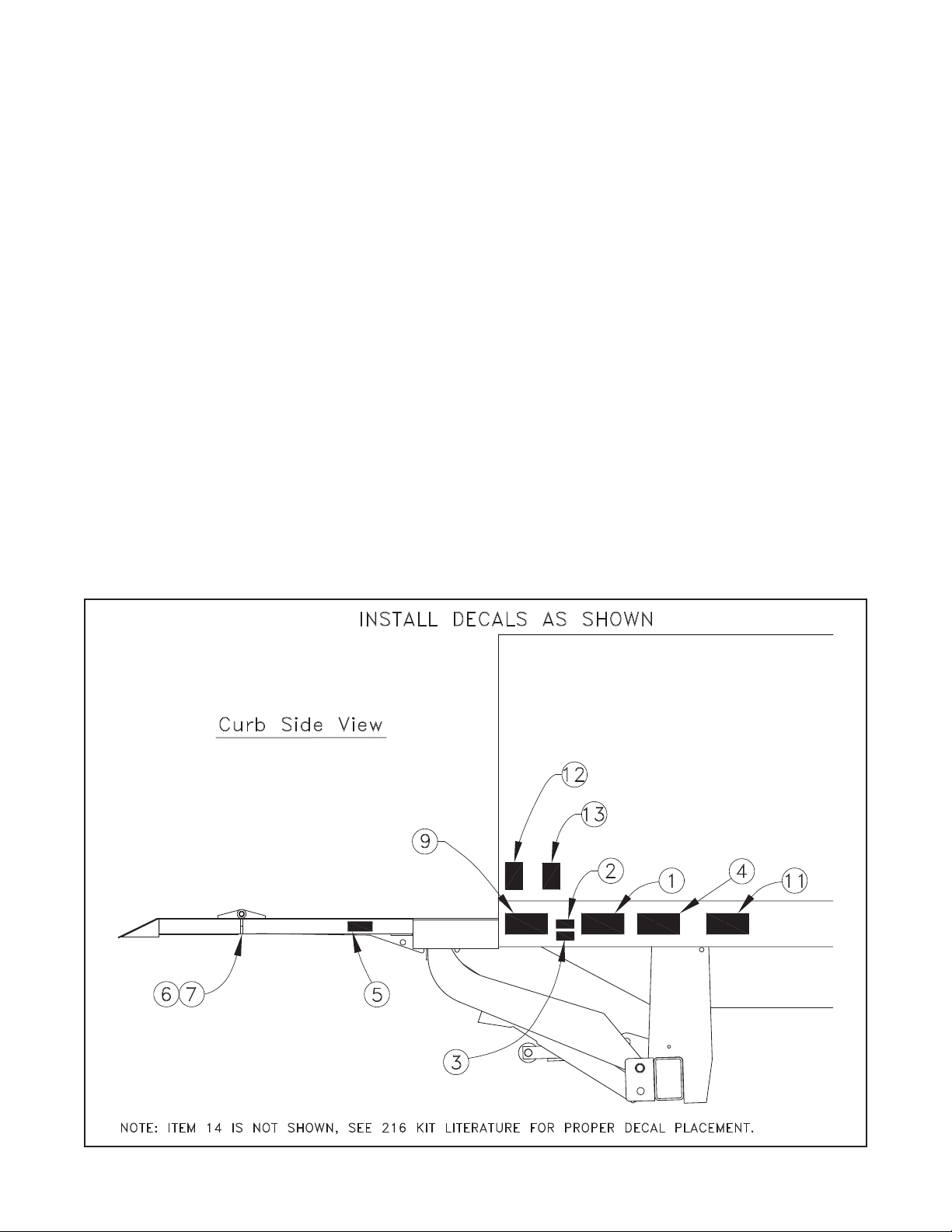
+ DO NOT operate this Thieman liftgate without the Owner's Manual for this model present
on the vehicle and without all decals present and legible, as guides for proper liftgate
operation and maintenance. (see the "Inspection and Location of Decals" section of this
manual. For replacement Owner's Manuals, decals, etc. call Thieman at 419-586-7727. For
the latest manuals and warnings for each liftgate, visit our website at
www.thiemantailgates.com. Note: manuals and warnings update regularly.
+ DO NOT operate this liftgate unless you have been properly instructed and have read and
understood the Owner's Manual, operating instructions and all decals. Improper operation
of this lift may result in serious personal injury and/or damage to the liftgate.
+ The vehicle must be securely and properly braked on level ground before using the liftgate.
+ All protective covers and guards must be in place before operating the liftgate.
+ Before using liftgate, check for signs of improper maintenance or damage(unusual noises,
vibrations, fails to operate freely, missing hardware, cracked welds ... etc). DO NOT use the
lift if these are evident. Only an authorized Thieman distributor is qualified to do repairs on
the liftgate. DO NOT attempt to do your own repairs or modify this liftgate. Altering this
product will void all warranties and may damage the liftgate or even cause serious injury. If
any repairs, adjustments, or maintenance not covered in this manual are required, contact
your nearest Thieman distributor or call Thieman at 419-586-7727.
2.

3.
+ THIS IS NOT A PERSONNEL LIFT. Because of the pinch point between the platform and
the truck, fall hazards, unstable loads, etc., riding the lift may cause severe personal injury
or death. ALWAYS stay clear of the liftgate when in operation. Do NOT ride the liftgate.
+ This liftgate is intended for the use of loading and unloading cargo only, it is not to be used
for anything other than this.
+ DO NOT OVERLOAD THE LIFT ATE. Each liftgate has a specific maximum capacity for
lifting and lowering. The standard maximum rated capacities of the M series liftgates differs
with each model as follows:
M/MLB/MDC/MDCLB25 - 2500 lbs. Maximum Load
M/MLB/MDC/MDCLB30 - 3000 lbs. Maximum Load
NOTE: Special options can lower the maximum rated capacities below those shown above.
Be certain you know what the maximum rated capacity is for your particular liftgate.
+ NEVER off-center the load on the platform, from side to side or away from truck as this may
overload the liftgate. The center of weight of the load should NEVER be placed beyond the
center of the platform load surface, away from truck. Loads should be placed close to
platform edge nearest truck. See figure 1.
+ NEVER allow any part of the load to extend beyond the edges of the platform's flat load
surface.
+ NEVER allow any part of the load to extend over or on, the tapered ramp portion of the
platform unless the platform is lowered completely to the ground and the ramp is supported
by the ground.
+ NEVER lift or lower unstable loads.
+ NEVER operate liftgate if platform load surface is slippery.
+ Make certain that the area below the platform is clear before and at all times during
operation of the liftgate.
+ Load and unload the platform from the rear and not from the side of the platform.
+ Never operate lift trucks on or over any part of the platform.
+ Follow the maintenance guide as outlined in this manual.
+ NEVER move vehicle unless platform is properly stowed and power is off. Locking cams
must be properly pinned before transit.
+ Anytime the vehicle is washed, this liftgate MUST be inspected to MAKE SURE all parts
are properly lubricated and have the appropriate protectants. Failure to replace lubricants
and protectants after washing the vehicle, may lead to improper operation of the liftgate,
accelerated corrosion, and possible component failure.
PARTS ORDERIN PROCEDURE
When ordering parts, please include all the information asked for below. If this information is
not available, a complete written description or sketch of the required part will help Thieman
identify and deliver the needed part to you.
THE FOLLOWIN INFORMATION MUST BE INCLUDED:
1. Serial Number – Thieman liftgate serial numbers can be found on the tag located on the
front side of the trunnion tube.
2. Model Number and Capacity.
3. Platform size and Material – Steel or Aluminum.
4. Part number.
5. Description.
6. Quantity required.

4.
WARNING: POSITION OADS PROPER Y ON P ATFORM
NEVER off-center the load on the platform, from side to side or away from truck as
this may overload the liftgate. The center of weight of the load should NEVER be placed
beyond the center of the platform load surface, away from truck. oads should be
placed close to the platform edge nearest truck. If a load is not uniformly distributed,
then the heaviest portion should be closest to the edge of the platform nearest the
truck. NEVER allow any part of the load to extend beyond the edges of the platform's
flat load surface. NEVER allow any part of the load to extend over or on, the tapered
ramp portion of the platform unless the platform is lowered completely to the ground
and the ramp is supported by the ground.

5.
OPERATING INSTRUCTIONS
Caution
Be sure to operate liftgate at a safe distance and never improperly load platform as this may
cause personal injury or damage to the liftgate.
UNFO DING OF P ATFORM
1. Raise platform by pushing up switch until stow pin on platform is off the spacer latch.
2. Move spacer handle counterclockwise to disengage spacer latch and hold.
3. Lower the platform by pushing the down switch until the lift arms contact the ground.
4. rasp platform handle on curb side and rotate outward to a horizontal position.
RAISING OF P ATFORM
5. Push up switch to raise platform to bed height.
OWERING OF P ATFORM
6. Push down switch to lower platform to the ground.
C OSING OF P ATFORM
7. Lower platform to the ground.
8. Fold over extension and grasp platform handle to raise manually to vertical position.
9. Push up switch to raise completely until stow pin and spacer latch have engaged for stow-
ing.
THERMA DATA:To avoid overheating the motor do not operate this unit for more than 8
cycles/10 minutes with the maximum load. The motor then must be allowed to completely cool
down to ambient temperature before cycling the lift again. This unit also has a 15% duty cycle,
which means the liftgate can be cycled no more than 3 cycles/10 minutes constantly with a
maximum load.
MAINTENANCE GUIDE
The following inspection and maintenance operations should be performed at the recommended
intervals or anytime the liftgate shows signs of abuse, and improper or abnormal operation.
MONTH Y INSPECTION AND MAINTENANCE
Operate the liftgate throughout its entire operational cycle and check the following:
1. Check that there are no unusual noises or vibrations.
2. Check platform height relative to bed height. If platform is lower, adjust cylinder with a
13/16 wrench to obtain the necessary height.
3. Check for apparent damage to the liftgate such as bent or distorted members, any cracked
welds which may have resulted from overloading or abuse.
4. Check for excessive wear in the following areas:
A. Platform hinge pins and lift arms
B. All cylinder pins, bolts, and clevis
C. Platform extension pivots
D. Linkage pins and clevises
5. Check that the platform pivot pins are in place and retained by their proper retainers.
6. Check that all protective covers and guards are properly in place and secured.
7. Check for oil leaks in these areas:
A. Lift cylinder
B. Hydraulic hose-replace if it shows signs of wear or cracking.
C. Hydraulic fittings-tighten or replace as may be required to stop leakage.
8. Check the oil level in the pump reservoir. With the liftgate in the lowered position and the
platform at ground level the oil should be within 1/2” from the top of the reservoir. See chart
on next page for oil applications.
9. Check that all wiring and battery cable connections are tight and free of corrosion.

6.
10. Lubrication of the M series liftgate should be as follows for all user conditions:
Area of Tailgate Type of Lubrication* Frequency
Kicker roller asm rease 50 cycles
Pump oil change see chart below yearly
Control handle pivots SAE 10 or 20 oil 50 cycles
Platform extension pivots SAE 10 or 20 oil 50 cycles
The major pivot points of the M series liftgate have special bushings that do not require
lubrication.
For -40 to 120 F use #0 rade grease.
For -20 to 200 F use #1 rade grease.
HYDRAU IC F UID CHART
Temperature
Range
-75 to 165°F
-20 to 130°F
-50 to 80°F
Acceptable
Fluids
Exxon Univis J-26
Dexron III
Exxon Superflo ATF
Shell Donax T
Shell Aero Fluid 4
Mobil Aero HFA
Exxon Univis J-13
MIL H-5606
Semi-Annual Inspection
1. Perform the procedures outlined in the Monthly Inspection and Maintenance.
2. Repaint original painted components as necessary to prevent rust and corrosion from
reducing structural integrity of original components.
3. Inspect pump motor by:
A. Disconnecting battery cable
B. Remove motor end cover
C. Examine the armature brushes for wear. (Brushes should be replaced if they are less
than 1/8” long).
D. Clean all residue out from inside of the motor housing.
E. Apply several drops of light weight machine oil to the armature shaft bearing in the
motor end cover and reassemble the motor end cover.
4. If the hydraulic oil in the reservoir is dirty:
A. Unfold platform and lower platform to the ground.
B. Drain the oil from the hydraulic system and flush the entire system.
C. Remove reservoir from pump and clean suction line filter. Also clean out any contami-
nants inside reservoir. Remount reservoir when completed.
D. Replace the oil as outlined in Section 9 under Monthly Maintenance and Inspection.
11. Check the pump relief pressure and also the motor amperage at this pressure. These val-
ues should be as follows:
Model Max. Amp. Draw Relief Pressure (psi)
M/MLB 25/30 ET 205 2500
M/MLB 25/30 EST 255 2650
MDC/MDCLB 25/30 ET 180 2000
MDC/MDCLB 25/30 EST 215 2000

7.
E ECTRICA PICTORIA S

8.
INSPECTION AND OCATION OF DECA S
Inspect all decals listed below to be certain they are in the proper location and they are
legible.
A DECA S MUST BE IN P ACE AND EGIB E OR A WARRANTIES ARE VOID!
Item Part Name Part Number
1 Warning Decal-off center 4671050
2 Fast Idle Decal 4650150
2 PTO Decal 4650140
3 Danger Decal-no riding 4609
4 Operating Decal 4650890
5 Capacity Decal-1600# 4650750
5 Capacity Decal-2000# 4650100
5 Capacity Decal-2500# 4650110
5 Capacity Decal-3000# 4650120
6 Warning Decal-pinch point 4604
7 Handle decal 4605
8 Thieman Nameplate 4650800
9 Urgent Warning Decal 4681
10 Reflector (3) 5705
11 Wiring Decal- ravity Down 4612
11 Wiring Decal-Power Down 4614
12 Warning Decal 4620
13 Caution Decal 4650770
14 Receiver Latch Decal (Optional) 4683

9.
Item Part Number Description
1 31421-001 Platform Asm 7232 1
1 31421-002 Platform Asm 8432 1
1 31420-001 Platform Asm 7236 1
1 31420-002 Platform Asm 8436 1
1 3468-001 Platform Asm 7242 1
1 3468-002 Platform Asm 8442 1
2 31417-001 Main Section Weld 7232 1
2 31417-002 Main Section Weld 8432 1
2 31418-001 Main Section Weld 7236 1
2 31418-002 Main Section Weld 8436 1
2 31659-001 Main Section Weld 7242 1
2 31659-002 Main Section Weld 8442 1
3 31717-001 Extension Weld 7232 1
3 31717-002 Extension Weld 8432 1
3 31097-001 Extension Weld 7236 1
3 31097-002 Extension Weld 8436 1
3 31678-001 Extension Weld 7242 1
3 31678-002 Extension Weld 8442 1
4 3023-001 Support Tube 1 1 1
5 5101260 Spring 2 2 3
6 5050 Pin 1 1 1
7 8120378 Nut .50 1 1 1
8 9414074 Locknut .50 1 1 1
9 5781017 Retaining Ring 5 5 5
10 5051 Pin 1 1 1
11 5056 Pin 2 2 2
12 5711 Shoulder Eye Bolt 1 1 1
13 8107-011 Washer 2 2 2
14 5504-016 Bushing 4 4 4
P ATFORM ASSEMB Y - 32+5, 36+6, 42+6 (STEE MAIN/EXT.)
Platform Size/Qty
32+5 36+6 42+6

10.
Item Part Number Description
1 3465-001 Platform Asm 7242+10 - M25 1
1 3465-002 Platform Asm 8442+10 - M25 1
1 3467-001 Platform Asm 7242+10 - MDC30 1
1 3467-002 Platform Asm 8442+10 - MDC30 1
2 31418-001 Main Section Weld 7242+10 - M25 1
2 31418-002 Main Section Weld 8442+10 - M25 1
2 31677-001 Main Section Weld 7242+10 - MDC30 1
2 31677-002 Main Section Weld 8442+10 - MDC30 1
3 31654-001 Extension Weld 7242+10 - M25, MDC30 1 1
3 31654-002 Extension Weld 8442+10 - M25, MDC30 1 1
4 31655-001 Ramp Asm 7242+10 - M25, MDC30 1 1
4 31655-002 Ramp Asm 8442+10 - M25, MDC30 1 1
5 3023-001 Support Tube 1 1
6 5101260 Spring 2 3
7 5050 Pin 1 1
8 8120378 Nut .50 1 1
9 9414074 Locknut .50 1 1
10 5781017 Retaining Ring 9 9
11 5051 Pin 1 1
12 5056 Pin 4 4
13 5711 Shoulder Eye Bolt 1 1
14 8107-011 Washer .62 4 4
15 5504-016 Bushing 4 4
16 5708-001 Spring Pin 2 2
17 8109-008 .25 Set Screw 1 1
18 5746 Cable 2 2
19 8180126 Screw .38 x 1.50 2 2
20 9413534 Locknut .38 2 2
21 8180122 Screw .38 x 1.00 1 1
22 27215 Retainer 1 1
P ATFORM ASSEMB Y - M25 OR MDC30, 42+10 RET. (STEE MAIN/EXT.)
ate Model/Qty.
M25 MDC

11.
Item Part Number Description
1 31426-001 Platform Asm 7242W-M 1
1 31426-002 Platform Asm 8442W-M 1
1 3466-001 Platform Asm 7242W-MDC 1
1 3466-002 Platform Asm 8442W-MDC 1
2 31418-001 Main Section Weld 7242W-M 1
2 31418-002 Main Section Weld 8442W-M 1
2 31677-001 Main Section Weld 7242W-MDC 1
2 31677-002 Main Section Weld 8442W-MDC 1
3 31155-001 Extension Weld 7242-M, MDC 1 1
3 31155-002 Extension Weld 8442-M, MDC 1 1
4 3023-001 Support Tube 1 1
5 5101260 Spring 2 2
6 5050 Pin 1 1
7 8120378 Nut .50 1 1
8 9414074 Locknut .50 1 1
9 5781017 Retaining Ring 5 5
10 5051 Pin 1 1
11 5056 Pin 2 2
12 5711 Shoulder Eye Bolt 1 1
13 8107-011 Washer .62 2 2
14 5504-016 Bushing 4 4
P ATFORM ASSEMB Y - M OR MDC, 42W (STEE MAIN/EXT.)
ate Model/Qty.
M25 MDC

12.
Item Part Number Description Qty.
1 3469-001 Platform Asm 7248W 1
1 3469-002 Platform Asm 8448W 1
2 31680-001 Main Section Weld 7248W 1
2 31680-002 Main Section Weld 8448W 1
3 31682-001 Extension Weld 7248WAL 1
3 31682-002 Extension Weld 8448W AL 1
4 3023-001 Support Tube 1
5 5101260 Spring 2
6 5050 Pin 1
7 8120378 Nut .50 1
8 9414074 Locknut .50 3
9 5781017 Retaining Ring 1
10 5051 Pin 1
11 8119 Shoulder Screw .50 2
12 5711 Shoulder Eye Bolt 1
13 8107-011 Washer .62 2
14 5504-016 Bushing 4
15 8106-009 Lockwasher .63 2
16 8106-008 Lockwasher .50 2
17 5504-013 Bushing 2
18 8120377 Nut .38 1
19 21042 Latch 1
20 8120388 Washer .38 1
21 8180126 Screw .38 x 1.50 1
P ATFORM ASSEMB Y - 48W (STEE MAIN/A UM. EXT.)

13.
Item Part Number Description Qty.
1 3446-001 Platform Asm 7236 1
1 3446-002 Platform Asm 8436 1
2 31425-001 Main Section Weld 7236 1
2 31425-002 Main Section Weld 8436 1
3 31346-001 Extension Weld 7236 1
3 31346-002 Extension Weld 8436 1
4 3023-001 Support Tube 1
5 5101260 Spring 1
6 5050 Pin 1
7 8120378 Nut .50 1
8 9414074 Locknut .50 3
9 5781017 Retaining Ring 5
10 5051 Pin 1
11 5056 Pin 2
12 5711 Shoulder Eye Bolt 1
13 8107-011 Washer .62 2
14 5504-021 Bushing 2
15 5504-019 Bushing 2
P ATFORM ASSEMB Y - M25 36+6 (A UM. MAIN/EXT.)

14.
Item Part Number Description Qty.
1 3470-001 Platform Asm 7236 1
1 3470-002 Platform Asm 8436 1
1 31731-001 Platform Asm 7240 1
1 31731-002 Platform Asm 8440 1
2 31728-001 Main Section Weld 7236, 7240 1
2 31728-002 Main Section Weld 8436, 8440 1
3 31738-001 Extension Weld 7236 1
3 31738-002 Extension Weld 8436 1
3 31730-001 Extension Weld 7240 1
3 31730-002 Extension Weld 8440 1
4 3023-001 Support Tube 1
5 5101260 Spring 1
6 5050 Pin 1
7 8120378 Nut .50 1
8 9414074 Locknut .50 3
9 5781017 Retaining Ring 1
10 5051 Pin 1
11 8119 Shoulder Bolt .62 2
12 5711 Shoulder Eye Bolt 1
13 8107-011 Washer .62 2
14 5504-021 Bushing 2
15 5504-019 Bushing 2
16 8106-008 Lockwasher .50 2
17 8106-009 Lockwasher .62 2
18 5504-013 Bushing 2
P ATFORM ASSEMB Y - M30 36+6/MDC 40+6 (A UM. MAIN/EXT.)

15.
Item Part Number Description Qty.
1 31734-001 Platform Asm 7242+10 1
1 31734-002 Platform Asm 8442+10 1
2 31728-001 Main Section Weld 7242+10 1
2 31728-002 Main Section Weld 8442+10 1
3 31732-001 Extension Weld 7242+10 1
3 31732-002 Extension Weld 8442+10 1
4 31735-001 Ramp Asm 7242+10 1
4 31735-002 Ramp Asm 8442+10 1
5 5101260 Spring 1
6 5050 Pin 1
7 8120378 Nut .50 1
8 9414074 Locknut .50 3
9 5781017 Retaining Ring 5
10 5051 Pin 1
11 8119 Shoulder Bolt .62 2
12 5711 Shoulder Eye Bolt 1
13 8107-011 Washer .62 4
14 5504-021 Bushing 2
15 5504-019 Bushing 2
16 8106-008 Lockwasher .50 2
17 8106-009 Lockwasher .62 2
18 5504-013 Bushing 2
19 5056 Pin 2
20 5746 Cable 2
21 8180126 Screw .38 x 1.50 1
22 27215 Retainer 1
23 8180122 Screw .38 x 1.00 1
24 8109-008 Set Screw .25 1
25 5708-001 Spring Pin 2
26 3023-001 Support Tube 1
27 9413534 Locknut .38 2
P ATFORM ASSEMB Y - 42+10 RET. (A UM. MAIN/EXT.)

16.
Item Part Number Description Qty.
1 31729-001 Platform Asm 7248W 1
1 31729-002 Platform Asm 8448W 1
2 31728-001 Main Section Weld 7248W 1
2 31728-002 Main Section Weld 8448W 1
3 31682-001 Extension Weld 7248W 1
3 31682-002 Extension Weld 8448W 1
4 3023-001 Support Tube 1
5 5101260 Spring 1
6 5050 Pin 1
7 8120378 Nut .50 1
8 9414074 Locknut .50 3
9 5781017 Retaining Ring 1
10 5051 Pin 1
11 8119 Shoulder Bolt .62 2
12 5711 Shoulder Eye Bolt 1
13 8107-011 Washer .62 2
14 5504-021 Bushing 2
15 5504-019 Bushing 2
16 8106-008 Lockwasher .50 2
17 8106-009 Lockwasher .62 2
18 5504-013 Bushing 2
19 8107-001 Washer .38 1
20 21042 Latch 1
21 8103-002 Nut .38 1
22 8108-002 Screw .38 x 1.50 1
P ATFORM ASSEMB Y - 48W (A UM. MAIN/EXT.)

17.
Item Part Number Description Qty.
1 3500-001 Spacer Asm - 96" 1
1 3500-002 Spacer Asm - 102" 1
2 2404-002 Control Shaft - 96" Spacer Asm. 1
2 2404-003 Control Shaft - 102" Spacer Asm. 1
3 31592 Latch 1
4 5101100 Spring 1
5 5701043 Handle 1
6 23168-005 Flat Bar 1
SPACER ASSEMB Y

18.
Item Part Number Description
1 31412-001 Trunnion Weld - M 1 1 1
1 31412-002 Trunnion Weld - MLB 1
1 31412-003 Trunnion Weld - Pintle 1 1 1
2 21030 Mounting Plate 1 1 1 1
3A 31413 Idler Arm 1 1 1
3B 31736 Idler Arm 1
4 31414 Lift Arm Weld 1 1 1 1
5 31416 Pivot Bar Weld-4.13 1 1
5 31427 Pivot Bar Weld-4.25 1 1
6 5701330 Roller 1 1 1 1
7 5031 Pin 1 1 1 1
8 5781008 Retaining Ring 2 2 2 2
9 8271291 Zerk 1 1 1 1
10 5047 Pin 4 4 4 4
11 5702371 Spring 4 4 4 4
12 5075 Pin 2 2 2 2
13 5504-005 Bushing 2 2 2 2
14 5708-001 Spring Pin 4 4 4 4
15 5504-017 Bushing 2 2 2 2
16 5504-016 Bushing 6 6 6 6
17 5789 Wear Pad 2
18 5793010 Self-Tapping Screw - .25-20 4
TRUNNION, IFT ARM, &ID ER ARMS - M25/30
Platform Size/Qty
32+5 36+6 42+10 42W

1 31676-001 Trunnion Weld 1 1 1 1 1 1 1 1
1 31676-003 Trunnion Weld-Pintle 1 1 1 1 1 1 1 1
2 21030 Mounting Plate 1 1 1 1 1 1 1 1
3A 31413 Idler Arm 1 1
3B 31674 Idler Arm 1
3C 31736 Idler Arm 1
3D 31683 Idler Arm 1 1 1 1
4 31675 Lift Arm 1 1 1 1 1 1 1 1
5 31679 Pivot Bar Weld-4.00 1
5 31427 Pivot Bar Weld-4.25 1
5 31416 Pivot Bar Weld-4.13 1 1
5 31681 Pivot Bar Weld-4.19 1 1
5 31737 Pivot Bar Weld-4.38 1 1
6 5701330 Roller 1 1 1 1 1 1 1 1
7 5031 Pin 1 1 1 1 1 1 1 1
8 5781008 Retaining Ring 2 2 2 2 2 2 2 2
9 8271291 Zerk 1 1 1 1 1 1 1 1
10 5047 Pin 4 4 4 4 4 4 4 4
11 5702371 Spring Pin 4 4 4 4 4 4 4 4
12 5075 Pin 2 2 2 2 2 2 2 2
13 5504-005 Bushing 4 4 4 4 4 4 4 4
14 5708-001 Spring Pin 4 4 4 4 4 4 4 4
15 5504-017 Bushing 2 2 2 2 2 2 2 2
16 5504-016 Bushing 6 6 6 6 6 6 6 6
17 5789 Wear Pad 2 2 2 2 2 2
18 5793010 Self Tap Screw-.25-20 4 4 4 4 4 4
19 8130999 Washer .69 6 6
20 5702290 Rubber Bumper 2 2 2 2
21 9413447 Locknut .31 2 2 2 2
22 8120386 Washer .25 4 4 4 4
23 8180091 Screw .31 x 2.25 2 2 2 2
42+6, 42W 42+10 RET 48W 48W-LB 48W AL 48W
40+6 AL ST AL AL-LB
19.
TRUNNION, IFT ARM, AND ID ER ARMS - MDC25/30
Item Part
Number Description
Platform Size Qty.

20.
Item Part Number Description Qty
1 4404 Pump Asm-Items 2 to 6 1
2 4421420 Pump Bracket 1
3 4421350 Mounting Bracket 1
4 4423520 Motor 8111 1
5 4468 Solenoid Start Switch 1
6 4420410 Breather Cap 1
7 5704 Cover 1
8 5700100 Strap 1
9 4930-001 MF-MAORB 90° 3
10 4948-001 Flow Control - 1.5 PM 1
11 4936-001 MAORB-MAORB 90° 1
12 5053 Pin 1
13 4298 Cylinder Asm 1
14 4300030 Battery Cable #2 X 25’ 1
15 4350 Cable Lug 1
16 8180126 Screw .38 x 1.50 5
17 8106-010 Internal Tooth Lockwasher .38 10
18 8120377 Nut .38 5
19 8120388 Flatwasher .38 4
20 31445 Toggle Switch ASM 1
21 5504-001 Bushing 2
22 4422860 Pushbutton Control-Optional 1
23 8111-005 Screw #10 x .75 2
24 4318-002 round Cable #2 x 2' 1
25 8104-006 Screw .31 x 1.00 1
26 5702371 Spring Pin 1
27 5059 Pin 1
28 5781008 Retaining Ring 2
29 4951-012 Hose 38" 2
30 4301770 Circuit Breaker 150 Amp 1
31 4318-001 Battery Cable #2 x 2’ 1
32 4319-002 Shrink Wrap 1
33 4941-001 MJ-MORB Straight 1
M25/30 PUMP ASSEMB Y - POWER DOWN
This manual suits for next models
14
Table of contents
Other THIEMAN Lifting System manuals
Popular Lifting System manuals by other brands

John Bean
John Bean EELR537A Installation, operation & maintenance manual

National Auto Tools
National Auto Tools NSS-8000 instructions

Atlas
Atlas PV-15PX Installation & operation manual

Aquatec
Aquatec orca Operating instruction

Ravaglioli
Ravaglioli RAV4300 Translation of the original instructions

Ariens
Ariens 79614000 instruction sheet

LSP inc.
LSP inc. LSC850D owner's manual

morse
morse 195AM-A Operator's manual

Ranger Products
Ranger Products BendPak P-6 Installation and operation manual

REID LIFTING
REID LIFTING PORTA GANTRY Assembly & Operation guide

Savaria
Savaria V1504 owner's manual

EZ-ACCESS
EZ-ACCESS TiLT Toilet Incline Lift Installation and user manual